
15
INSTRUCTION MANUAL FOR ARC WELDING MACHINE
IMPORTANT: BEFORE STARTING THE EQUIPMENT,
READ THE CONTENTS OF THIS MANUAL, WHICH
MUST BE STORED IN A PLACE FAMILIAR TO ALL US-
ERS FOR THE ENTIRE OPERATIVE LIFE-SPAN OF THE
MACHINE.
THIS EQUIPMENT MUST BE USED SOLELY FOR WELD-
ING OPERATIONS.
1 SAFETY PRECAUTIONS
WELDING AND ARC CUTTING CAN BE HARM-
FUL TO YOURSELF AND OTHERS. The user
must therefore be educated against the hazards, sum-
marized below, deriving from welding operations. For
more detailed information, order the manual code
3.300.758
ELECTRIC AND MAGNETIC FIELDS - May be dangerous.
· Electric current following through any con-
ductor causes localized Electric and Mag-
netic Fields (EMF). Welding/cutting current
creates EMF elds around cables and pow-
er sources.
The magnetic elds created b high currents ma affect
the operation of pacemakers. Wearers of vital electronic
equipment (pacemakers) shall consult their physician be-
fore beginning any arc welding, cutting, gouging or spot
welding operations.
Exposure to EMF elds in welding/cutting ma have oth-
er health effects which are now not known.
· All operators should use the followingprocedures in or-
der to minimize exposure to EMF elds from the welding/
cutting circuit:
- Route the electrode and work cables together
- Secure them with tape when possible.
- Never coil the electrode/torch lead around your body.
- Do not place your body between the electrode/torch
lead and work cables. If the electrode/torch lead
cable is on your right side, the work cable should also
be on your right side.
- Connect the work cable to the workpiece as close as
possible to the area being welded/cut.
- Do not work next to welding/cutting power source.
EXPLOSIONS
· Do not weld in the vicinity of containers under
pressure, or in the presence of explosive dust,
gases or fumes. · All cylinders and pressure reg-
ulators used in welding operations should be handled
with care.
ELECTROMAGNETIC COMPATIBILITY.
This machine is manufactured in compliance with the in-
structions contained in the standard IEC 60974-10 (CL.
A), and must be used solely for professional purposes
in an industrial environment. There may be potential
difculties in ensuring electromagnetic compatibilit in
non-industrial environments.
DISPOSAL OF ELECTRICAL AND ELECTRONIC
EQUIPMENT.
Do not dispose of electrical equipment togeth-
er with normal waste!In observance of European
Directive 2002/96/EC on Waste Electrical and Electron-
ic Equipment and its implementation in accordance with
national law, electrical equipment that has reached the
end of its life must be collected separately and returned
to an environmentally compatible recycling facility. As the
owner of the equipment, you should get information on
approved collection systems from our local representa-
tive. By applying this European Directive you will improve
the environment and human health!
IN CASE OF MALFUNCTIONS, REQUEST ASSISTANCE
FROM QUALIFIED PERSONNEL.
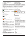
1.1 WARNING LABEL
The following numbered text corresponds to the label
numbered boxes.
B. Drive rolls can injure ngers.
C. Welding wire and drive parts are at welding voltage dur-
ing operation — keep hands and metal objects away.
1 Electric shock from welding electrode or wiring can kill.
1.1 Wear dry insulating gloves. Do not touch electrode
with bare hand. Do not wear wet or damaged gloves.
1.2 Protect yourself from electric shock by insulating
yourself from work and ground.
1.3 Disconnect input plug or power before working on
machine.

16
2 Breathing welding fumes can be hazardous to your
health.
2.1 Keep your head out of fumes.
2.2 Use forced ventilation or local exhaust to remove fumes.
2.3 Use ventilating fan to remove fumes.
3 elding sparks can cause explosion or re.
3.1 eep ammable materials awa from welding.
3.2 elding sparks can cause res. ave a re extin-
guisher nearby and have a watchperson ready to use
it.
3.3 Do not weld on drums or any closed containers.
4 Arc rays can burn eyes and injure skin.
4.1 Wear hat and safety glasses. Use ear protection and
button shirt collar. Use welding helmet with correct
shade of lter. ear complete bod protection.
5 Become trained and read the instructions before
working on the machine or welding.
6 Do not remove or paint over (cover) label.
2 GENERAL DESCRIPTIONS
2.1 SPECIFICATIONS
This welding machine is a DC power source built using
INVERTER technology, engineered to weld with all types
of coated electrodes (cellulosic type not included) and
with TIG welding process with scratch starting and high
frequency.
MUST NOT BE USED TO DEFROST PIPES.
2.2 EXPLANATION OF THE TECHNICAL SPECIFICA-
TIONS LISTED ON THE MACHINE PLATE
This machine is manufactured according to the following
international standards:
IEC 60974-1 / IEC 60974-3 / IEC 60974-10 (CL. A) / IEC
61000-3-11 / IEC 61000-3-12 (see note 2).
N° . Serial number, which must be indicated on
any request regarding the welding machine.
3
~
f
1
f
2
Three-phase static frequency converter
transformer - rectier.
Drooping characteristic.
MMA Suitable for welding with covered electrodes.
TIG Suitable for TIG welding.
U0. Secondary open-circuit voltage.
X. Duty cycle percentage.
The duty cycle expresses the percentage of
10 minutes during which the welding machine
can run at a certain current without overheat-
ing.
I2. Welding current
U2. Secondary voltage with current I2
U1. Rated supply voltage
3~ 50/60Hz Three-phase 50 or 50 Hz power supply.
I1 Max Max. absorbed current at the corresponding
current I2 and voltage U2.
I1 eff This is the maximum value of the actual cur-
rent absorbed, considering the duty cycle.
This value usually corresponds to the capacity
of the fuse (delayed type) to be used as a pro-
tection for the equipment.
IP23S Degree of housing protection.
Grade 3 as the second digit means that this
machine may be stored, but it is not suitable
for use outdoors in the rain, unless it is pro-
tected.
S
Suitable for use in high-risk environments.
NOTES:
1- The machine has also been designed for use
in environments with a pollution rating of 3.
(See IEC 60664).
2- This equipment complies with a IEC 2-61000-
3 standard provided that the allowed maxi-
mum impedance Zmax of the unit is lower
or equal to 0.093 (Art. 369) - 0,044 (Art. 370)
- 0,031 (Art. 371) at the interface point be-
tween the user unit and the mains. The tter
or the unit user are responsible for connect-
ing the unit to a power supply with a maxi-
mum allowed system impedance Zmax low-
er or equal to 0.093 (Art. 369) - 0,044 (Art.
370) - 0,031 (Art. 371). If required, they may
contact the electric power supplier to check
this value.
2.3 DESCRIPTION OF PROTECTION DEVICES
2.3.1 Thermal protection
This machine is protected by a number of temperature
probes, which prevent the machine from operating if the
allowable temperatures are exceeded. The thermostat
tripping is signalled by the glowing abbreviation “tH0"
or "tH1" on display D1 located on the control panel.
2.3.2 Alarm display
When the machine detects a temporary alarm, displays
D1 and D2 show a ashing wording related to the alarm
cause (see paragraph 5).
2.3.3 Error display
When the machine detects a serious alarm, displays D1
and D2 show a wording "Err" followed by the relevant
error code.
In this case, switch off the machine and contact technical
service (see par. 5).
3 INSTALLATION
Make sure that the supply voltage matches the voltage
indicated on the specications plate of the welding ma-
chine.
When mounting a plug, make sure it has an adequate ca-
pacity, and that the yellow/green conductor of the power
supply cable is connected to the earth pin.
The capacity of the overload cutout switch or fuses in-
stalled in series with the power supply must be equiva-

17
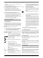
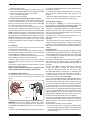
Fig. 1
Art. 370
BI
BF
BL
BM
BS
BO
BD
BB
BA
BN
BT
BU
BV
BZ
BH
BC
BP
BQ
BG
BE
BR
Art. 369
BS
BO
BD
BB
BA
BH
BC
BP
BQ
BG
BE
BR
Fig. 1

18
lent to the current I1max. absorbed by the machine.
3.1. GENERAL NOTES.
Only skilled personnel should install the machine. All
connections must be carried out according to regulations
in force, and in full observance of safety laws (IEC 26-23
/ IEC CLC 62081).
Also make sure the insulation of the cables, electrode
clamps, sockets and plugs are intact, and that the size
and length of the welding cables are compatible with the
current used.
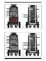
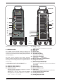
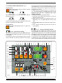
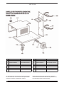
3.2 DESCRIPTION OF THE EQUIPMENT (Fig.1).
BA) Output terminal, negative (-).
BB) Output terminal, positive (+).
BC) 10-pin connector.
Remote controls described in paragraph 4 must be
connected to this connector.
Between pin 3 and 6 a clean contact is availbale
that signals the arc ignition (Max 0.5 A - 125 VAC /
0.3 A - 110 VDC / 1A - 30 VDC).
BD) Fitting (1/4 gas)
Used to connect TIG welding torch gas hose .
BE) Main switch.
BF) Tank cap.
BG) Power cable
BH) Gas suppl tting .
BI) Hot water inlet tting
(use only for TIG torches).
BL) Cold water outlet tting
(use only for TIG torches).
BM) Slot to inspect the coolant uid level.
BN) Fittings for TIG torches
(there must be no short-circuits).
BO) Connector Type DB9 (RS 232).
To be used for updating the power source software
or rmware.
BP) Fuse holder.
BQ) Power supply socket.
BR) Pressure switch socket.
BS) USB socket.
To be used for updating the power source rmware.
BT) Cooling unit pressure switch cable.
BU) Cooling unit fuse holder.
BV) Cooling unit main switch .
BZ) Cooling unit power cable.
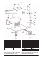
Art. 371
BI
BF
BL
BM
BS
BO
BC
BB
BA
BN
BT
BU
BV
BZ
BH
BD
BP
BQ
BG
BE
BR
Fig. 1

19
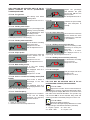
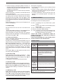
3.3 CONTROL PANEL DESCRIPTION (Fig. 2).
T1 process key.
With a long pressure of this key, LEDs L1 or L2 are
alternatively chosen.
LED L1 (TIG) LED L2 (MMA)
With a short pressure of this key, LEDs L35 or L36 are
alternatively chosen.
LED L35 (DC) LED L36 (AC)
2 LEDs will be always selected: one between LED L1 and
L2 and one between LED L35 and L36.
T2 program key.
One of the LEDs L3, L4, L5, L6 or L7 lights when
selected.
LED L3 - (manual) spot welding.
After selecting the welding current (LED L28) and the spot
welding time (LED L34) using key T8, set the values using
the knob M1.
This welding mode can only be selected in start-up mode
with HF (LED L9). The operator presses the torch trigger,
the arc lights and shuts off automatically after the pre-set
spot welding time. In order to weld the following spot, it is
necessary to release the torch trigger and press it again.
Range from 0.1 to 30 s.
To obtain points in sequence split up by intervals, the
item “tin” (time interval) is available from the second
functions menu; this item is displayed only if spot
welding is selected.
To activate the function proceed as follows:
1. Press keys T7 and T8 at the same time to enter the
“Second Functions” menu.
2. Brie press ke T8 until the display D1 shows the
abbreviation "tin". The display D2 will show the word
"OFF".
3. Turn knob M1 to select the time interval. Range from 0.1
to 25 s.
4. Press keys T7 and T8 at the same time to return to
normal display.
LED L4 - 2-stage TIG welding (manual).
B pressing the torch trigger the current moves to rst
level (LED L23) and remains there for the time previously
regulated and displayed by the LED L24 before reaching
the welding current in the “slope-up” time indicated by the
LED L25 the reaching of the welding current is indicated
by the start-up of the LED L28; when the torch trigger
is released, the current starts to drop, taking the “slope-
down” time indicated by the LED L30, before reaching the
Fig. 2
L9 L8 L13 L12 L14 L15 L16 D1 L17 L41 D2 T5 L18 M1L3 L10L4
L27
L28 L29 L30 L31 L32L26L25L24L23L22L22L22L22L40T8T7
L1
L20
L21
T6
L34
L33
L2
L5
L35
L6
L36
L7
T2
L42
T1
L11
T3
T4
L37
L38
L39
L19

20
third current LED L31 where it stays for the time regulated
and displayed by the LED L33.
In this position the pedal control accessory ART. 193 can
be connected.
NOTE: in order for art. 193 to work well set:
1. rst current value (LED L23) at the desired one as pedal
minimum value
2. rst current time at zero (LED L24).
3. slope-up and slope-down time at zero (LED L25 and
L30)
4. third current at the minimum.
LED L5 - 5-stage TIG welding (automatic).
This program differs from the previous one in that the arc
is both started and shut off by pressing and releasing the
torch trigger.
LED L6 - TIG welding with three levels of
current.
To set the three minimum welding currents, proceed as
follows:
Press key T8 until the LED L28 lights, then adjust the
main current value using knob M1.
Press key T7 until the LED L23 lights, then adjust the
initial current value using knob M1.
Press key T8 until the LED L31 lights, then adjust the nal
current value using knob M1.
hen the arc strikes, the current reaches the rst setting
(LED L23lit); By keeping the key pressed, the operator
can maintain this current as long as desired (for example
until the part is heated). Upon releasing the torch trigger,
the current passes from rst
to second
level during the
slope time (LED L25); once the 2
nd
level of welding current
is reached the LED L28 lights.
In order to pass to the 3rd current level the torch trigger is
to be pressed and kept pressed, while the current reaches
the 3rd value selected, in the slope time (LED L30): The
LED L31 will light, and the LED L28 will go off.
To switch off, press the torch trigger.
LED L7 - TIG welding with 4-stage current
levels.
To set the welding currents, proceed as follows:
Press key T8 until the LED L28 lights, then adjust the main
current value.
Press key T7 until the LED L23 lights, then adjust its
value; later on it is possible to adjust also this current time
LED L24.
Press key T8 until LED L29 lights, then adjust its value.
Press key T8 until LED L31 lights, then adjust its value.
Later on it is possible to adjust also this current time LED
L33.
By pressing and releasing the torch trigger, the current
moves to rst level (LED L23) and stays there for the
time previously regulated and displayed by the LED L24
before reaching the welding current in the “slope-up”
time indicated by the LED L25 the reaching of the welding
current is indicated by the start-up of the LED L28.
Should it be necessary to reduce the current during
welding, without shutting off the arc (for instance when
changing the welding material or working position, moving
from horizontal to upright, etc.), press and immediately
release the torch trigger, the current reaches the second
set value, the LED L29 lights and the LED L28 shuts off.
When the torch trigger is released, the current starts to
drop and takes the “slope-down” time indicated by the
LED L30, before reaching the third current LED L31
where it stays for the time regulated and displayed by the
LED L33.
In order to go back to the previous main current, repeat
the same torch trigger pressing and releasing action, the
LED L28 lights while LED L29 shuts off.
To stop welding at any time, simply hold down the torch
trigger for more than 0.7 seconds, then release it; the
current starts to gradually decrease in the time previosly
set (LED L20 lit) until reaching the crater current (LED
L31).
T3 Mode key.
With a long pressure (more than 0.7 sec) of this
key LEDS L8 or L9 are alternatively chosen.
With a short pressure (less than 0.7 sec) of this
key LEDS L10 or L11 are alternatively chosen.
2 LEDs will be always selected: one between LED L8 and
L9 and one between LED L10 and L11.
LED L8 - TIG welding with contact starting
(striking).
LED L9 - TIG welding starting with high
voltage/frequency device.
LED L10 - CONTINUOUS TIG welding.
LED L11 - PULSE TIG welding.
The pulse frequency is adjustable from 0.1 to
2,500 Hz (LED L27), peak current and base current can
be activated via LEDS L28 and L29, respectively, and are
adjustable using the knob M1.
With pulse frequency from 0.1 to 1.1 Hz display D1
alternatively shows peak current (main) and base current;
LEDs L28 and L29 are alterantively on.
With pulse frequency over 1.1 Hz the display D1 shows
the mean current between these two.
Key T4:
B brie pressing it snerg, where available, is
activated and selects LEDS L12, L13, L14, L15
, and L16 (see paragraph 3.7.4).
If, after selecting the parameters, the electrode diameter
is not conrmed, a brief pressure of this ke exits snerg.
If on the contrar, after conrming the parameter, snerg
is to be exited, it is necessary to press it for a long time
(1.5 s).
LED L13: Material.
The types of materials that may be selected are
in relation to the welding process and are:
In TIG AC, aluminium (Al), and magnesium (Mg).
In TIG DC, stainless steel (SS), copper (Cu), iron (Fe) and
titanium (Ti).

21
3. Additionally, with LED L17 (Hold) lit, it displays the last
welding voltage.
4. The numerical value of the magnitudes selected with
keys T7 or T8.
LED L19
It turns on after the intervention of a remote
control (Torches – remote controls – pedal control).
LED 20.
This lights up when the cooling unit is on.
LED L17 - Hold.
It signals that the values shown on the displays
D1 and D2 (normally current and voltage) are those used
during last welding. Activated at the end of each welding
session.
LED L21 Lock.
Indicates that the panel ha been blocked in
order to avoid undesired modications.
Key T5.
Selects and saves programs.
The welding machine can save nine welding
programs P01…..P09, and call them up using this
button. A work program PL is also available.
Selection:
If this ke is brie pressed the displa D1 shows the
number of the program following the one being used. If
it has not been saved the message will ash, otherwise it
will remain steady. LED L18 turns on.
Saving (see par. 3.6):
Once the program has been selected, hold for more
than 1.5 seconds to save the data. As conrmation, the
program number on the display D1 will stop ashing.
Key T8.
When this key is pressed, the following LEDS
light in succession, going from left to right: L37-
L38-L39-L40-L22-L23-L24-L25-L28-L26-
L27-L29-L34-L30-L31-L33-L32.
Warning! only those LEDS that refer to the chosen welding
mode will light; e.g. in continuous TIG welding LED L27,
that represents the pulse frequency, will not glow.
Each LED shows the parameter that can be set by means
of knob M1 during the time when the LED is glowing. 5
seconds after the last change the concerned LED shuts
off and LED L28 turns on again showing the main welding
current.
Key T7.
Like keyT8 but moving in the opposite direction,
from right to left.
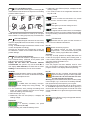
LED L14: Welding position.
The abbreviations that appear on the display D1
meets ISO 6947 standards and correspond to the welding
positions listed in gure 3.
45°
1F
PA
1G
PA
2G
PC
2F
PB
3F
PF
PG
3G
PF
PG
4F
PD
4G
PE
Fig. 3
ASME standard abbreviations are made up of one gure
and one letter. For clarity purposes, they are listed below.
LED L15: Thickness.
The display D1 lights and shows the set current,
while the display D2 shows the thickness corresponding
to the current.
Turning knob M1 changes the thickness and the current
will also be adjusted accordingly.
Obviously the thickness and corresponding current will
be measured in relation to the material and the welding
position settings.
LED L16: Electrode diameter.
The electrode diameter is displayed as a result
of the material setting (LED L13, of the position (LED
L14), and of the thickness (LEDL15).
Display D2 will show the electrode diameter
recommended; the operator may use the knob M1, to
also display other diameters, but these will be shown
ashing to indicate that they are not recommended.
Knob M1.
Normally adjusts the welding current (LEDL28).
Furthermore, if a function is selected with keyT8
this knob adjusts its size.
Display D1.
Shows:
1. In MMA, when not welding, the open-
circuit voltage and, during welding, the
load voltage.
2. In TIG continuous, when pressing the welding torch
trigger, but without welding, the open-circuit voltage
and, while welding, the load voltage.
3. Menu entries (par. 3.3.1).
4. Additionally, with LED L17 (Hold) lit, it displays the
welding voltage.
Display D2.
Shows:
1. in stand-by conditions, the preset
current(LED L28).
2. during welding, the measured welding current.

22
LEDS THAT MAY BE SELECTED ONLY IN TIG DC
(DIRECT CURRENT) OR TIG AC (ALTERNATING
CURRENT) WELDING:
LED L22 - Pre-gas time.
Gas delivery time before
welding starts.
Range from 0.05 s to 2.5 s.
LED L23 - Welding start current.
This is a percentage of the
welding current (LED L28).
Pre-set adjustment is 25%
of welding current.
Range from 1 to 100%.
The displayed value is in amperes [A].
LED L24 - Welding start current time.
It is the duration of welding
start current time.
Range from 0 to 30 s.
Pre-set adjustment is 0 s.
LED L25 - Slope up time.
This is the time in which the
current reaches the set
current value.
Range from 0 to 10 s.
Pre-set adjustment is 0 s.
LED L28- Main welding current.
It is the main welding
current value.
The displayed value is in
amperes [A].
Range from 5 to 500.
LED L29 - basic or second level welding current (FOR
PULSE).
This current is always a
percentage of the main
current.
The displayed value is in
amperes [A] between 1 and
100%. Pre-set adjustment is 50 %.
LED L27 - Pulse Frequency
Range from 0.1 to 2,500 Hz.
In DC and AC welding
procedure the frequency
increase results in:
1. higher arc concentration.
2. reduction of the thermically altered area.
LED L26.
Adjusts the percentage
ratio between the peak
current time L28 and the
frequency L27.
Pre-set adjustment is 50 %.
LED L34.
Indicates the spot welding
time (see description of
LED L3).
LED L30 - Slope down time.
This is the time in which the
current reaches the value
of welding end, crater ller
or arc shutdown.
LED L31 - Welding end current (crater arc).
This current setting is used
particularly for closing the
nal crater.
Range from 1 to 100%.
The displayed value is in
amperes [A]. Pre-set adjustment is 10 %.
LED L33 - Welding end current time (crater arc).
It is the duration of welding
end current time.
Range from 0 to 30 s.
LED L32 - Post-gas.
Sets gas output time when
welding is over.
Range from 0 to 30 s.
LED THAT MAY BE SELECTED ONLY IN TIG AC
(ALTERNATING CURRENT) WELDING MODE:
LED L37 - Start.
Adjusts the “hot-start” level to maximize starts in
TIG AC mode for each electrode diameter. When
this LED lights the display D2 shows a numerical value
that refers to the electrode diameters. The operator may
use the knob M1 to set the diameter being used and
obtain a good start immediately. Range from 0.5 to 4.8.
LED L38 - Wave.
Selects the welding waveform.
When this LED lights display D2 shows a number
corresponding to the selected waveform (see table).
11 = square - square 22 = sine - sine
33 = delta - delta 12 = square - sine

23
13 = square - delta 23 = sine - delta
21 = sine - square 32 = delta - sine
31 = delta - square.
Default = square - sine (12).
This combination of numbers may be changed using the
encoder M1.
NOTE: The rst number that makes up the gure refers
to the negative or penetration half-wave, the second
number refers to the positive or cleaning half-wave.
Changing the type of waveform may also reduce
noise in the arc in AC welding.
LED L39 - Hz.
Adjusts the frequency of the alternating current.
Range 50-100 Hz.
LED L40 - Adjusts the wave balance.
Adjusts the percentage of the negative
(penetration) half-wave in the alternating current
period.
Range -10/0/10 where 0 = 65% (recommended) -10 =
50% and 10 = 85%.
Consequences due to value increase
1. Better welding penetration.
2. Less piece cleaning.
LED L41:
LED indicating that the device to reduce the risk
of electric shock is in good working order.
Key T6 gas test.
hen this ke is pressed, the gas ows out for 30
seconds. If pressed again the ow stops.
Led L42 MIX:
The start-up of this led indicates that “MIX”
welding has been set, i.e. an alternation of alternate and
direct current. The purpose of this welding is to obtain
greater penetration with respect to traditional aluminium
alternate current welding.
To start up this welding, the AC welding must have been
set (L1+L36 ) in continuous mode (L10). To activate the
function proceed as follows:
1. Press keys T7 and T8 at the same time to enter the
“Second Functions” menu.
2. Brie press ke T8 until the display D1 shows the
abbreviation "ACM" (AC Mix). The display D2 will show
the word "OFF".
3. Turn knob M1 to select "On".
4. Only by activating the item “ACM” will it be possible
to select the abbreviation “ACd” which is the ratio
between the AC part and the DC part of the period.
10 – 80% period adjustment. Default=50%
5. Press keys T7 and T8 at the same time to return to
normal display.
CAUTION: it is normal for the MIX welding to take the
form of a pulse when continuous welding has been
selected.
Consequences due to ACd value increase:
1. Better welding penetration
2. Fewer deformations.
3. Quicker creation of the weld pool.
4. Less piece cleaning.
AAd = Adjustment of amplitude of the negative half wave.
Adjustable from the second functions menu. Permits
adjusting the amplitude of the negative half wave which
regulates alternate current welding penetration.
Adjustment = -/+ 80% of amplitude Default = 0
Consequences due to a value increase
1. Narrower arc.
2. Better welding penetration.
3. Reduced pickling.
4. Less electrode deformation
3.3.1 Menu of second functions.
Access to “second functions” menu is
obtained by pressing simultaneously keys
T7 and T8.
Exit from menu is always obtained by pressing
simultaneously keys T7 and T8.
Display D1 shows the function abbreviation, display D2
shows its value that can be adjusted by means of knob
M1.
The existing functions are:
1. Cooling unit (TIG only).
H2O
Range:
OFF = off (manufacturer’s setting).
OnC = Continuous always on.
OnA = automatic start-up.
2. EST (Evo Start) enable TIG DC.
The enabling of this function forces the welding
machine to start with a synergic pulsed current. Once
the time preset for automatic pulsation has passed,
switch is made to the welding current selected from
the panel.
The aim of this function is to quickly create the thin
metal plate welding melting bath or create a stable
bath with very low currents.
Default = OFF
Regulation =0.1 – 10 Sec.
3. ELF (Evo Lift) TIG DC must be enabled with H.F.
With function enabled the operation starts with contact
between the electrode and the piece being worked.
The instant the short circuit is solved, a high voltage/
frequency discharge is triggered which lights the arc.
The purpose of this function is to make cold and
precise welds on the metal plates.
Default = OFF
Regulation =OFF - ON.
4. tln. Spot pause time (LED L3) (only high frequency
TIG).
Adjusts the pause time between two spot welding
processes.
Range:
OFF = off; (manufacturer’s setting).
MIN = 0.0 s.

24
MAX = 25.0 s.
ACM = Activation of MIX welding (only TIG AC)
ACd = Duty cycle of AC part compared to entire
MIX period (only active if ACM On).
AAd = adjustment of amplitude of the negative half
wave (active in welding with alternate current).
5. HS (only MMA)
Percentage of hot-start current:
in order to improve electrode start-up the power source
delivers an overcurrent as against the current set.
Manufacturer’s setting: 50%.
MIN = 0 %
MAX = 100 %
6. tHS (MMA only)
Duration of hot-start current.
Manufacturer’s setting: 0.15%.
MIN = 0 s
MAX = 0.5 s
7. AF (MMA only)
Percentage of arc-force current.
This is a percentage of the welding current.
This overcurrent facilitates transfer of melt metal drops.
Manufacturer’s setting: 30%.
MIN = 0 %
MAX = 100 %
8. USb
This function is used to update the machine;
To do this proceed as follows:
1. Fit a USB ash drive containing the le with extension
“fwu” relating to the Cebora rmware of the welding
machine to be updated into the BS connector.
NOTE. The USB ash drive must be formatted with
le sstem FAT 32 and the le must be copied in the
BIN folder.
2. Enter the second functions menu and select the
USb function of the display screen D1. On the
display screen D2 “rEM” (remove) appears.
3. With the encoder M1 set ”UPd” (update) on the
display screen D2.
4. Press key T5 for longer than 3 seconds to start the
update sequence. Wait a few minutes. At the end of
the update sequence, the welding machine will be
operative again.
5. Remove the ash drive.
9. FAC (Resetting of Settings)
ALL resets all.
NoP resets all except JOBs.
PRG deletes all JOBs saved.
Once the desired option has been set, press key T5 for
activation.
3.4. WELDING WITH COVERED ELECTRODES (MMA).
- This welding machine is suitable for welding all types of
electrodes which can be welded in direct current, with
the exception of cellulosic (AWS 6010).
- Check that switch BE is in O position, then connect the
welding cables in compliance with the polarity requested
by the manufacturer of the electrodes you are going to
use; connect the earth cable terminal to the workpiece
as close as possible to the welding point and make sure
that there is a good electric contact.
- Do not touch the torch or electrode clamp simultaneously
and the mass terminal at the same time.
- Turn the machine on using the switch BE.
- Select MMA process, by pressing key T1 until LED L2
lights.
- Adjust the current according to electrode diameter,
welding position and type of joint to be made.
- Always remember to shut off the machine and remove
the electrode from the clamp after welding.
If you wish to adjust the Hot-start and Arc force
functions, see second functions (paragraph 3.3.1).
3.5. TIG WELDING.
By selecting TIG (LED L1) with contact start-up or HF
(LED L8 or L9), you can weld:
- in TIG AC welding, aluminium, brass, and magnesium
- in TIG DC welding, stainless steel, iron, and copper.
Connect the mass cable connector to the positive pole (+)
of the welding machine, and the terminal to the workpiece
as close as possible to the welding point, making sure
there is good electrical contact.
Connect the power connector of the TIG torch to the
negative pole (-) of the welding machine.
Connect the torch controlling connector to connector BC
of the welding machine.
Connect the tting of the torch gas hose to the BD
machine connector and the gas hose coming from the
clinder pressure regulator to the gas tting BH.
3.5.1 Cooling unit (optiona for Art. 369).
If you use a water cooled welding torch, use the cooling
unit.
Insert the torch cooling hoses in the ttings BI and BL
of the cooling unit, being careful to correctly place the
delivery and return.
3.5.1.1 Description of protection devices.
- Coolant pressure protection device.
This protection is achieved by means of a pressure
switch, inserted in the uid deliver circuit, which controls
a microswitch. Low pressure is indicated b the ashing
message H2O on the display D1.
3.5.1.2 Start-up
Unscrew the cap BF and ll the tank (the equipment is
supplied with approximatel one liter of uid).
It is important to periodically check, through the slot BM,
that the uid remains at the “max” level”.
Insert the pressure switch connector and the power cord
into the sockets BR and BQ.
Turn on the machine.
To select the operating mode of the cooling unit, proceed
as follows:

25
1. Select the TIG Process.
2. Press at the same time keys T7 and T8 and hold both
down until the display D1 shows the abbreviation H2O.
3. Select the operation by means of knob M1.
OnC = continuous operation
OnA = automatic operation
To exit this selection brie press es T7 and T8.
If on start-up the uid does not circulate, it is necessar to
remove air from the tubes. In this case shut off the power
source, connect one end of the torch hose to tting BL
and insert the other end into the tank.
Turn the power source on for approximately 10 to 15
seconds while checking that water exits the tube. Shut
off the welding machine, connect the tube to the tting BI.
NOTE: “Automatic operation” means that the cooling unit
starts when the torch trigger is pressed and stops running
approximately 2 minutes after the torch trigger is released.
Warning! If MMA electrode welding is selected, cooling
is not on and may not be selected. It is normal for the
machine display D1 to show the ashing message 2O
on start-up.
3.5.2 Start-up
Do not touch live electrical parts and output terminals
when the machine is powered.
At rst start-up, select the operation mode b means of
key T3 and the welding parameters by means of key T8
and knob M1 as indicated in paragraph 3.3.
The inert gas ow must be set at a value (liters per minute)
approximately 6 times the electrode diameter.
If gas-lens type accessories are used, the gas delivery
can be reduced by approximately 3 times the electrode
diameter.
The ceramic nozzle diameter must be between 4 and 6
times the electrode diameter.
When ou have nished welding, do not forget to shut
off the machine and close the gas cylinder valve.
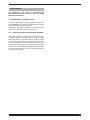
3.5.3 Preparing the electrode
Be especially careful when preparing the electrode tip.
Grind it so that it has a vertical groove as shown in the
gure 4.
FIG. 4
WARNING: LOOSE HOT METAL PARTS may cause
personal injuries, res and damages to the equipment;
TUNGSTEN CONTAMINATION may lower the quality of
the weld.
• Use only a grinder equipped with adequate safety guards
to shape the tungsten electrode and wear protections for
face, hands and body.
• To shape the tungsten electrodes, use a hard, ne-
grained abrasive grinding wheel used solely for this
purpose.
• Grind the tungsten electrode tip in a conical form and a
length 1.5 to 2 times the electrode diameter (g. 3).
3.5.4 “Synergy” welding.
The purpose of “Synergy” is to give the operator a
quick guidance to TIG welding parameters setting. It is
therefore not compulsory, but only a suggestion.
“Synergic” relationships between current thickness and
electrode diameter have been developed using Ceriati
grey 2% electrodes (EN 26848 WC20), at an alternating
current frequency of 90 Hz.
The teasts were carried out with the waveform n°. 12
(square penetration - sinusoidal cleaning).
The logic:
The operator sets the type of material to be welded, the
welding position and thickness in relation to the welding
process; an electrode diameter is suggested based on
these choices, and if conrmed the machine prepares for
welding.
Turn Synergy on.
Brie (less than 1.5 s) press ke T4: LED L12 (Syn) lights
simultaneously with LED L13 (material). Display D1 shuts
off and Display D2 shows an abbreviation corresponding
to the material to be welded (see description LED L13).
Turn the knob M1 to choose.
Pressing the key T4 again conrms the choice of material
and causes the LED L14 to light; the display D2 then
shows the welding positions available (see description of
LED l14).
Turn the knob M1 to choose. Pressing key T4 again
conrms the position selected and causes LED L15
to light; the display D1 shows the set current, while
the display D2 shows the thickness in millimeters that
corresponds to the current (see description of LED 15).
A further pressing of key T4 conrms the choice of
thickness and causes LED L16 to light.
One or more electrode diameters are proposed based on
the set choice of material, position, thickness and current.
The recommended electrode will be proposed rst and
the numerical value of the diameter will always be steadily
lit, next to the letter A; if the amp setting selected for
welding falls within the current range of two diameters,
the second choice of electrode diameter will be proposed
only by turning knob M1. The second choice will also be
displayed steadily lit. If you turn the knob further, on the
display D2 the diameter above the second choice and
the diameter below the rst choice will be ashing.
iven that the electrode diameter mainl denes the start
current level (LED L34) and the minimum current (LED
L23), the operator may choose a combination that is not
recommended.
At this point the operator has two choices:
1. To exit snerg without conrming the choices made.
To do this, brie press ke T4, the LED L12 shuts off
and the panel displays the settings in effect before you
entered synergy.

26
2. Conrm snerg b pressing ke T4 for more than 1.5
seconds. At this point all synergy functions are set and,
if selected using the key T8, the display D2 shows the
message “AU” (automatic).
The LED L12 remains lit to conrm that the parameters
have been set.
hen the electrode is conrmed, the LED L16 shuts off
and the LED L12 lights.
To summarize, when ou conrm the electrode diameter
(by holding down the button T4 when the LED L16 is
selected) the start (LED L37), wave (LED L38), Hz (LED
L39), balance (LED L40) and current (LED L23) functions
are arranged according to the automatic logic described
previously.
hen the electrode is conrmed, the LED L16 shuts off
and the LED L12 lights.
3.6. SAVING (JOB)
With this function the user can save in the machine the
settings
chosen and call them up later on. The machine features 9
memory positions for user settings, called JOBs.
When the operator is working and using one of these 9
settings saved LED L18 (JOB) is on and display D1 brie
shows the wording P01... P09.
3.6.1 Saving of parameters.
While in main display page (LED L18 off) the operator can
change any welding parameter.
B brie (one or more times) pressing ke T5 the user can
select the memory position chosen in a range from P01 to
P09. Display D1 ashes, D2 shows: --- and all LEDs are
off to indicate that that memory position is empty. With
a longer pressing of key T5 (for over 1.5 s) the machine
saves the settings in the selected position, the display
stops ashing and the LEDs light to indicates the setting
saved.
From position P09 b brie pressing ke T5 the user
exits JOB mode (LED L18 off).
3.6.2 Creating a JOB.
Brie press ke T5 until nding a position P..... empt
(display D1 ashing and displa D2 showing ---). Going
from left to right use keys T7 and T8 and knob M1 all
welding parameters desired.
A long pressure of key T5 saves those parameters.
3.6.3 Deleting a JOB.
Brie press ke T5 until reaching the desired position P...
(display D1 is not ashing), turn knob M1 until the display
D2 shows the wording DEL and press key T5 for over 1.5 s.
Display D1 starts ashing to indicate the OB has been
deleted.
3.6.4 Modifying a JOB.
Brie press ke T5 until reaching the desired position
(display D1 is not ashing) and use kes T7 and T8 and
knob M1 to modif the parameters selected. hen rst
modifying a parameter LED L18 starts ashing to indicate
that present position setting has been modied.
At this point it is possible:
• to overwrite present position: press key T5 till LED L18
stops ashing.
• to save in another position: brie press ke T5 until
reaching the new position desired and press key T5 for
a long time for the new saving.
• to cancel modications: press ke T5 ten times until
returning to the preceding position. LED L18 is not
ashing.
4 REMOTE CONTROLS
The following remote controls may be connected to adjust
the welding current for this welding machine
:
Art.1256 TIG Welding torch only START button. (water
cooled).
Art.1258 TIG torch with START and UP/DOWN buttons
(water-cooled).
Art. 193 Pedal control (used in TIG welding).
Art 1192+Art 187 (used in MMA welding).
Art . 1180 Connector to connect torch and pedal control
at the same time. Art 193 may be used in any
TIG welding mode with this accessory.
Controls that include a potentiometer adjust the
welding current from initial (LED L23) to current set
by means of knob M1.
Controls with UP/DOWN logic control welding current
from the minimum to the maximum value.
5 ERROR CODES
DISPLAY ERROR DESCRIPTION
TRG
ashing
Release the torch trigger
Err 54 Short circuit on secondary circuit
Err 56 Anomalous condition while welding
Err 58
Error of alignment between the rmware
versions or error during the auto-
upgrade phase (repeat the upgrade
procedure)
Err 61 Low supply voltage
Err 62 High supply voltage
TH 0 Output diodes overtemperature
TH 1 IGBT overtemperature
H2O
ashing
(followed by
Err 75)
Cooling pump problem (pressure switch)
H2O nc
ashing
Cooling pump problem (not connected)
In the case of an error code different from those listed
please contact technical service

27
6 MAINTENANCE
All maintenance jobs must be performed by
professional personnel according to the IEC 26-29
(IEC 60974-4) standard.
6.1 MAINTENANCE - POWER SOURCE
In case of maintenance inside the appliance, make sure
the switch BE is in “O” position and that the power supply
cable is disconnected from the mains.
Periodically, also clean the inside of the appliance and
remove any metal dust using compressed air.
6.2 HOW TO PROCEED AFTER MAKING REPAIRS.
After making repairs, always ensure the wires are fully
insulated between the primary side and the secondary
side of the machine. Avoid the wires coming into contact
with moving parts or parts that heat up during operation.
Fit all the clamps back as on the original machine so as
to avoid any contact between the primary and secondary
side in case of accidental lead breakage or disconnection.
Also t the screws back on with the toothed washers as
on the original machine.

147
QUESTA PARTE È DESTINATA ESCLUSIVAMENTE AL PERSONALE QUALIFICATO.
THIS PART IS INTENDED SOLELY FOR QUALIFIED PERSONNEL.
DIESER TEIL IST AUSSCHLIEßLICH FÜR DAS FACHPERSONAL BESTIMMT.
CETTE PARTIE EST DESTINEE EXCLUSIVEMENT AU PERSONNEL QUALIFIE.
ESTA PARTE ESTÁ DESTINADA EXCLUSIVAMENTE AL PERSONAL CUALIFICADO.
ESTA PARTE È DEDICADA EXCLUSIVAMENTE AO PESSOAL QUALIFICADO.
TÄMÄ OSA ON TARKOITETTU AINOASTAAN AMMATTITAITOISELLE HENKILÖKUNNALLE.
DETTE AFSNIT HENVENDER SIG UDELUKKENDE TIL KVALIFICERET PERSONALE.
DIT DEEL IS UITSLUITEND BESTEMD VOOR BEVOEGD PERSONEEL.
DENNA DEL ÄR ENDAST AVSEDD FÖR KVALIFICERAD PERSONAL.
AUTOV TO TMHVMA PROORIVZETAI APOKLEISTIKAV GIA TO EIDIKEUMEVNO PROSWPIKO.V

148
ART. 369

149
ART. 370

150
ART. 371

151
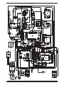
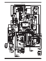
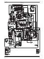
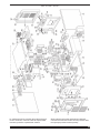
CODIFICA COLORI
CABLAGGIO ELETTRICO
WIRING DIAGRAM
COLOUR CODE
L NROSA-NERO PINK-BLACK
M GRIGIO-VIOLA GREY-PURPLE
N BIANCO-VIOLA WHITE-PURPLE
O BIANCO-NERO WHITE-BLACK
P GRIGIO-BLU GREY-BLUE
Q BIANCO-ROSSO WHITE-RED
R GRIGIO-ROSSO GREY-RED
S BIANCO-BLU WHITE-BLUE
T NERO-BLU BLACK-BLUE
U GIALLO-VERDE YELLOW-GREEN
V AZZURRO BLUE
CODIFICA COLORI
CABLAGGIO ELETTRICO
WIRING DIAGRAM
COLOUR CODE
A NERO BLACK
B ROSSO RED
C GRIGIO GREY
D BIANCO WHITE
E VERDE GREEN
F VIOLA PURPLE
G GIALLO YELLOW
H BLU BLUE
K MARRONE BROWN
J ARANCIO ORANGE
I ROSA PINK

152
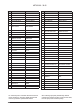
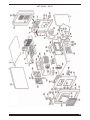
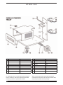
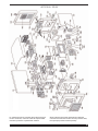
La richiesta di pezzi di ricambio deve indicare sempre:
numero di articolo, matricola e data di acquisto della
macchina, posizione e quantità del ricambio.
When ordering spare parts please always state the
machine item and serial number and its purchase data,
the spare part position and the quantity.
POS DESCRIZIONE DESCRIPTION
01 LATER ALE FISSO FIXED PANEL
02 COPERCHIO COVER
03 PIANO INTERMEDIO INSIDE BAFFLE
04 CIRCUITO DI MISURA MEASURE CIRCUIT
05 AUTOTRASFORMATORE AUTOTRANSFORMER
06 CIRCUITO ALIMENTAZIONE SUPPLY CIRCUIT
07
TRASFORMATORE DI PO-
TENZA TRIFASE
THREE PHASE POWER
TRANSFORMER
08 INTERRUTTORE SWITCH
09 PROTEZIONE PROTECTION
10 PANNELLO POSTERIORE REAR PANEL
11 CIRCUITO FILTRO RETE FILTER CIRCUIT
12 CORNICE FRAME
13 PANNELLO ALETTATO FINNED PANEL
14 PROTEZIONE PROTECTION
15 CAVO RETE POWER CORD
16 PRESSACAVO STRAIN RELIEF
17 RACCORDO FITTING
18 ELETTROVALVOLA SOLENOID VALVE
19 RACCORDO FITTING
20 CONNESSIONE CONNECTION
21 PRESA SOCKET
22 PORTAFUSIBILE FUSE HOLDER
23 MOTORE CON VENTOLA MOTOR WITH FAN
24 SUPPORTO MOTOVENTOLA MOTOR WITH FAN SUPPORT
25 ISOLAMENTO DISSIPATORE RADIATOR INSULATION
26 DISSIPATORE RADIATOR
27 SUPPORTO CENTRALE DX. RIGTH CENTRAL SUPPORT
28 CORNICE FRAME
29 ISOLAMENTO INSULATION
30 DIODO DIODE
31 KIT DIODO DIODE KIT
32 CAVALLOTTO JUMPER
33 CAVALLOTTO JUMPER
34 CAVALLOTTO JUMPER
35 TRASDUTTORE TRANSDUCER
36 CAVALLOTTO JUMPER
37 CIRCUITO TERMOSTATO THERMOSTAT CIRCUIT
38 I.G.B.T. I.G.B.T.
POS DESCRIZIONE DESCRIPTION
39 ISOLAMENTO INSULATION
40 KIT I.G.B.T. I.G.B.T KIT
41 SUPPORTO CAVALLOTTI JUMPERS SUPPORT
42 CIRCUITO DRIVER DRIVER CIRCUIT
43 ISOLAMENTO INSULATION
44 TRASFORM. DI POTENZA POWER TRANSFORMER
45 TRASFORMATORE HF HF TRANSFORMER
46 FONDO BOTTOM
47 PANNELLO ANTERIORE FRONT PANEL
48 CIRCUITO CONNETTORE CONNECTOR CIRCUIT
49 RACCORDO FITTING
50 RACCORDO FITTING
51 TAPPO CAP
52 PRESA GIFAS GIFAS SOCKET
53 PROTEZIONE PROTECTION
55 GOLFARA E YEBOLTS
56 CIRCUITO SERIALE SERIAL CIRCUIT
57 CIRCUITO PANNELLO PANEL CIRCUIT
58 CIRCUITO ALTA FREQUENZA HIGH-FREQ. CIRCUIT
59 PROTEZIONE PROTECTION
60 MANOPOLA KNOB
61 CIRCUITO FILTRO HF HF FILTER CIRCUIT
62 CIRCUITO DI CONTROLLO CONTROL CIRCUIT
63 GRUPPO I.G.B.T. IGBT UNIT
64 GRUPPO RESISTENZA RESISTANCE UNIT
65 CORNICE FRAME
66 SUPPORTO CENTRALE SX LEFT CENTRAL SUPPORT
67 DISSIPATORE RADIATOR
68 IMPEDENZA CHOKE
69 GOLFARA E Y EBOLTS
70 SUPPORTO MANICO HANDLE SUPPORT
71 MANICO HANDLE
72 PANNELLO PANEL
73 CORNICE FRAME
74 DISTANZIALE CORNICE FRAME SPACER
75 LATERALE SINISTRO LEFT SIDE PANEL
76 CONNESSIONE USB USB CONNECTION
77 CIRCUITO SENSORE RETE SENSOR CIRCUIT
78 PANNELLO CHIUSURA CLOSING PANEL
ART. 369.00 - 369.55

153
ART. 369.00 - 369.55
La pagina si sta caricando...
La pagina si sta caricando...
La pagina si sta caricando...
La pagina si sta caricando...
La pagina si sta caricando...
La pagina si sta caricando...
La pagina si sta caricando...
La pagina si sta caricando...
La pagina si sta caricando...
-
 1
1
-
 2
2
-
 3
3
-
 4
4
-
 5
5
-
 6
6
-
 7
7
-
 8
8
-
 9
9
-
 10
10
-
 11
11
-
 12
12
-
 13
13
-
 14
14
-
 15
15
-
 16
16
-
 17
17
-
 18
18
-
 19
19
-
 20
20
-
 21
21
-
 22
22
-
 23
23
-
 24
24
-
 25
25
-
 26
26
-
 27
27
-
 28
28
-
 29
29


Cebora EVO 260 T Instructions Manual
- Categoria
- Sistema di saldatura
- Tipo
- Instructions Manual
in altre lingue
- English: Cebora EVO 260 T
Documenti correlati
-
Cebora BI-WELDER TIG 2040 DC-HF Manuale utente
-
Cebora MIG 3540/T Manuale utente
-
-
Cebora EVO SPEED STAR 380 TC Manuale utente
-
-
-
-
-
-
Altri documenti
-
ESAB DTF 180 Manuale utente
-
ESAB DTB 275, DTB 375 Manuale utente
-
Panasonic RQL31 Istruzioni per l'uso
-
LG T6 Manuale utente
-
Hama 00050048 Manuale del proprietario
-
 luxform LED Garden Light Beehive Tripod Bronze Manuale utente
-
Kenwood CAW-COMUN1 Manuale del proprietario
-
Iqua Lino L10c Installation & User Manual
-
Lindy Single Display Ceiling to Floor Mount Manuale utente
