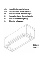
V-ZUG 64002 Guida d'installazione
- Categoria
- Cappe da cucina
- Tipo
- Guida d'installazione
Questo manuale è adatto anche per

de Installationsanleitung
en Installation Instructions
fr Instructions de montage
it Istruzioni per il montaggio
nl Installatieaanwijzing
tr Montaj kılavuzu
DHL 8
DHL 11

de
2
Sicherheitshinweise
Diese Bedienungsanleitung enthält
wichtige Hinweise, welche für einen
störungsfreien Betrieb der Haube
beachtet werden müssen. Bitte
bewahren Sie die Bedienungsanleitung
für späteres Nachschlagen oder zur
Problembehandlung sorgfältig auf.
Die Dunstabzugshaube darf nicht von
Personen (einschl. Kinder) mit einge-
schränkten physischen oder psychi-
schen Fähigkeiten oder mangels Erfah-
rung und/oder mangels Wissen benutzt
werden. Kinder müssen beaufsichtigt
werden, um sicherzustellen, dass diese
nicht mit dem Gerät spielen.
Abluft darf nicht über einen Rauchab-
zugskanal von anderen Geräten abge-
führt werden.
Mindestabstand zwischen Kochfeld und
Dunstabzugshaube muss eingehalten
werden.
Vorschriften über die Abführung der
Abluft müssen erfüllt werden.
Bei der Benutzung der Dunstabzugs-
haube können frei liegende Teile heiß
werden.
Stromanschluss der Haube nach gelten-
den Vorschriften. Ist der Anschluss nach
der Installation der Haube nicht frei zu-
gänglich, verwenden Sie bitte einen
geprüften bipolaren Schalter, welcher
nach der Überspannungskategorie III
eine vollständige Abschaltung garan-
tiert.
Der minimale Abstand zwischen Koch-
feld und Dunstabzugshaube beträgt
500 mm bei einem normalen Kochfeld
und 750 mm bei Verwendung von Gas.
Entsprechende Herstellerangabe müs-
sen berücksichtigt werden.
Bestimmungsmäßige
Verwendung
Dunstabzugshauben von V-ZUG dürfen
ausschließlich zur Beseitigung von beim
Kochvorgang entstehender Dämpfe und
Dünste in privaten Räumlichkeiten
verwendet werden. Jede andere
Verwendung gilt als sachwidrig, durch
welche Gefahren für Personen und
Gegenstände entstehen können.
Dunstabzugshauben dürfen nicht als
ständige Ablage von Gegenständen wie
z.B. Flaschen oder anderen Küchen-
utensilien verwendet werden.
Installation
Das Gerät darf nur von autorisiertem
Fachpersonal unter Beachtung aller
einschlägigen Vorschriften der
Stromversorgungsunternehmen sowie
der Bauverordnungsvorschriften der
Länder angeschlossen werden.
Zu beachten ist gleichfalls die
beiliegende Installationsanleitung!
Beschädigte Geräte dürfen nicht in
Betrieb genommen werden. Defekte
Teile müssen durch Originalteile ersetzt
werden. Reparaturen dürfen nur durch
autorisiertes Fachpersonal durchgeführt
werden.
Vergiftungsgefahr!
Wenn die Dunstabzugshaube im
A
bluftbetrieb gleichzeitig mit anderen
raumluftabhängigen Feuerstätten (z. B.
holz-, gas-, öl- oder kohlebefeuerte
Geräte) in einem Raum betrieben wird,
können tödliche Verbrennungsgase
durch einen entstehenden Unterdruck
im Raum zurückgeführt werden. Bitte
sorgen Sie daher immer für ausreichend
Zuluft! Der Unterdruck im Raum darf
nicht größer als 4 Pa (0,04 mbar) sein.
Brandgefahr!
Die Dunstabzugshaube darf nie ohne
F
ettfilter und muss immer unter Aufsicht
betrieben werden. Überfettete Filter
bedeuten Brandgefahr! Frittieren Sie
unter der Abzugshaube nur unter
ständiger Aufsicht! Achten Sie auf eine

de
3
regelmäßige Filterreinigung. Flambieren
ist unter der Abzugshaube nicht
gestattet! Gasgeräte dürfen unterhalb
der Abzugshaube nur mit aufgesetzten
Töpfen benutzt werden! Falls Sie mehr
als drei gasbetriebene Kochstellen
gleichzeitig nutzen, betreiben Sie bitte
die Abzugshaube auf der Leistungsstufe
„2“ oder höher. So wird ein Wärmestau
im Gerät vermieden.
Transport, Auspacken, Aufstellen
Wenn das Gerät aus kalter Umgebung
in den Betriebsraum gebracht wird, kann
Betauung auftreten. Bitte warten Sie bis
das Gerät temperaturangeglichen und
absolut trocken ist, bevor Sie es in
Betrieb nehmen.
Die Akklimatisationszeit ist abhängig
von Temperaturdifferenz und Gerät
sowie dessen Aufbau. Sie sollte aber
mindestens 12 Stunden betragen.
Gefahr durch elektrischen Schlag!
Reinigen Sie die Haube nicht mit einem
Dampfreiniger oder mit Wasserdruck.
Beim Reinigen der Haube muss diese
vorher vom Stromnetz getrennt werden.

de
4
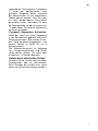
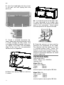
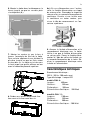
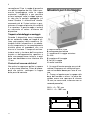
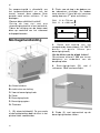
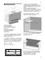
3. Löcher mit Hilfe der mitgelieferten
Bohrschablone H4.2587D bohren. (4
Löcher Ø4mm pro Befestigungswinkel).
Brettstärke beachten!
Auf Mindestabstand > 500 mm zwi-
schen Kochstelle und Unterkante der
Dunstabzugshaube achten.
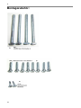
4. Befestigungswinkel (2.) mit 4 Schrau-
ben 20x6 mm befestigen.
5. Schlitten (3.) mit Gewindeeinsatz auf
die Befestigungswinkel stecken.
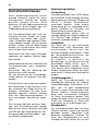
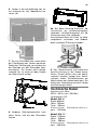
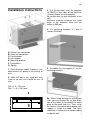
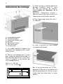
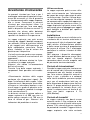
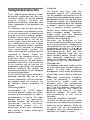
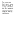
Montageanleitung
A: Abluftstutzen
B: elektrischer Anschluss
C: Vorderer Befestigungswinkel
D: Schlitten
E: Befestigungswinkel
F: Befestigungslöcher
G: Blechfeder
1. (Bei Abluftbetrieb) Geeignete Abluft-
führung bauseits in der Decke oder
Wand vorbereiten.
2. Ausschnitt für Haube in den Boden
des Einbauschrankes erstellen. Der
Boden sollte mindestens 19 mm stark
sein (ggf. durch ein 2. Brett verstärken).
DHL 8: A = 791 mm
DHL 11: A = 1091 mm
5a. Bei Abluftführung Richtung Wand:
Blech mit Lüfter und Abdeckblech auf
der Rückseite demontieren. Lüfter kann
ins Motorengehäuse gelegt werden.
283

de
5
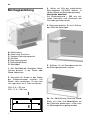
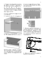
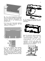
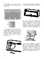
6. Haube in Ausschnittöffnung von un-
ten einführen bis die Federbleche ein-
rasten (4.).
7. Die vier Schrauben von unten durch
die Filteröffnung der Haube montieren.
Dabei den Schlitten ggf. verschieben bis
die Gewinde mit den Schrauben über-
einstimmen. Die Haube wird hochge-
schraubt, bis sie unten mit dem Kragen
am Oberschrank anliegt.
8. Vorderen Befestigungswinkel nach
unten führen und mit den Schrauben
fixieren.
8a.) Bei Abluft Richtung Rückseite, Ab-
luftschlauch mit Luftrückschlagventil
verbinden. Luftrückschlagventil mit Ab-
luftstutzen vom Lüfter verbinden.
Anschließend Blech mit Lüfter zu Moto-
rengehäuse schrauben und Abdeck-
blech auf obere Öffnung schrauben.
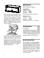
9. Den Abluftschlauch und elektrische
Anschlussleitung an die Haube heran-
führen. Darauf achten, dass der Abluft-
schlauch knickfrei verlegt wird. Abluft-
schlauch mittels Schlauchklemme am
Abluftstutzen der Haube befestigen. Die
elektrische Verbindung zwischen Haube
und Zuleitung erstellen.
Technische Daten
Anschluss ans Netz:
230 V / 50 Hz, max. 200 Watt
Leuchtmittel: LED
Modell DHL 8:
Breite: 800mm
Höhe: 355mm
Tiefe: 300mm
El ek tr isch er Gesamt anschluss-
wert: 200 Watt
Modell DHL 11:
B
reite: 1100mm
Höhe: 355mm
Tiefe: 300mm
El ek tr isch er Gesamt anschluss-
wert: 200 Watt

de
6
Entsorgung
Verpackung
Die Verpackung des Geräts ist recycle-
bar. Als Verpackungsmaterialien werden
Karton und Polyethylenfolie (PE) ver-
wendet. Diese Materialien sind auf um-
weltgerechte und den jeweiligen vor Ort
geltenden Vorschriften entsprechende
Weise zu entsorgen.
Umwelthinweise
Dieses Gerät ist entsprechend der euro-
päischen Richtlinie 2002/96/EG über
Elektro- und Elektronikaltgeräte (waste
electrical and electronic equipment -
WEEE) gekennzeichnet. Die Richtlinie
gibt den Rahmen für eine EU-weit gülti-
ge Rücknahme und Verwertung der
Altgeräte vor. Über aktuelle Entsor-
gungswege bitte beim Fachhändler in-
formieren.

en
7
Safety information
These operating and installation instruc-
tions contain important information that
must be observed to ensure safe and
reliable operation of the extractor hood.
Please store them in a safe place for
future reference. These operating in-
structions refer to several versions of
the appliance. They may contain de-
scriptions of certain features not found
on your model.
The extractor hood must not be used by
persons (incl. children) with impaired
physical or mental capabilities or per-
sons who lack experience and/or knowl-
edge of how to use it. Children must be
supervised to ensure that they do not
play with the appliance.
The appliance is not to be used by chil-
dren or persons with reduced physical,
sensory or mental capabilities, or lack of
experience and knowledge,
Unless they have been given supervi-
sion or instruction
Exhaust air must not be discharged into
a flue used for other appliances.
Minimum distance between hob surface
and lowest part of range hood
Regulations concerning the discharge of
exhaust air fulfilled
Accessible parts may become hot when
used with cooking appliances .
Connect the hood to a receptacle that
complies with current regulations and
placed in an accessible position. Where
the plug will not be in an accessible
position after installation, place an ap-
proved bipolar switch in accessible posi-
tion that provides full disconnection un-
der overvoltage category III conditions,
in accordance with local wiring rules
The minimum distance between the
supporting surface for the cooking ves-
sels on the hob and the lowest part of
the range hood is 500 mm when
the range hood is located above an
electric appliance and 750 mm when the
range hood is located above a gas ap-
pliance.
If the instruction for the installation of the
gas hob specify a greater distance, this
has to be taken into account
Intended use
The extractor hood may only be used to
extract kitchen vapours above the cook-
ing appliances in private households.
Any other use will be deemed to be im-
proper. Improper use of the hood may
pose a danger to persons and objects.
The extractor hood must not be used as
a shelf to store objects such as bottles,
spice jars or other loose objects.
Installation
The appliance may only be installed and
connected by an authorised technician
observing all relevant regulations of the
electric utility companies and the appli-
cable building regulations. During instal-
lation, observe the relevant instructions!
Damaged appliances may not be put
into operation. Defective parts must be
replaced with genuine parts. Repairs
should only be carried out by authorised
technical staff.
Danger of intoxication!
If the extractor hood is operated in ex-
traction mode at the same time as other
room-air-dependent fire appliances (e.g.
wood, gas, oil or coal-fired appliances)
in the same room, lethal combustion
gases may be directed back into the
room due to the resulting negative pres-
sure. For this reason, you must ensure a
sufficient air supply at all times! The
negative pressure in the room must not
exceed 4 Pa (0.04mbar).
Fire hazard!
The extractor hood must never be oper-
ated without the grease filter and must
always be used under supervision. Fil-
ters that are saturated with grease can
pose a fire hazard! Keep the extractor
hood under constant supervision when
deep-frying! Remember to clean out the

en
8
filters regularly. Flambéing under the
extractor hood is not allowed! Gas appli-
ances may only be used under the ex-
tractor hood with saucepans placed over
them! If you are using more than three
gas rings at the same time, operate the
extractor hood at power level "2" or
higher. This prevents the build-up of
heat in the appliance.
Preparing for use
The extractor hood model complies with
the relevant safety regulations for
kitchen appliances in private house-
holds. The requirements regarding the
installation location are described in the
user documentation supplied with the
appliance. If you have any doubts as to
whether your intended installation loca-
tion meets the requirements, please
contact our service department. Dam-
aged appliances may not be put into
operation. Defective parts must be re-
placed with genuine spare parts or parts
specified by V-ZUG. Repairs should
only be carried out by authorised techni-
cal staff.
Transport, unpacking, installation
Condensation may occur if the appliance
i
s brought into the installation site from a
cold environment. Please wait until the
appliance has adjusted to the tempera-
ture and is completely dry before operat-
ing it. The acclimatization period de-
pends on the temperature difference
and the type and design of the appli-
ance. However, it should be at least 12
hours.
Connecting the power supply
Check that the rated voltage indicated
on the appliance matches the mains
voltage in your area. Connection to the
incorrect voltage will damage or destroy
the appliance.
Before switching on the appliance,
check that all cables and lines are prop-
erly fitted and undamaged. Make sure in
particular that there are no kinks in the
cables, that they are not pulled too
tightly around corners and that no ob-
jects are resting on them. Also make
sure that all plug connections are se-
curely inserted. Faulty shielding or wir-
ing poses a health hazard (electric
shock) and can destroy other appli-
ances. Appliances with mains plugs are
fitted with a safety-tested mains cable
for the respective country of use and
may only be connected to a correctly
earthed safety socket. Otherwise, there
is a risk of electric shock. Make sure
that the socket on the appliance or the
domestic safety socket is easily accessi-
ble so that the mains cable can be un-
plugged from the socket in an emer-
gency or during servicing and mainte-
nance work.
Danger of electric shock!
Do not clean the hood with a steam
cleaner or water pressure cleaner. The
hood must be disconnected from the
power supply prior to cleaning.

en
9
Installation instructions
A: Exhaust air connection
B: Electrical connection
C: Front bracket
D: Nut support
E: Mounting bracket
F: Fixing holes
G: Spring
1. (For extraction mode) Prepare a suit-
able exhaust air guide in the ceiling, or
wall.
2. Make cut out in the fitted wall unit.
Floor of the wall unit should be min 19
mm.
DHL 8: A = 791 mm
DHL 11: A = 1091 mm
3. Drill Ø4mm holes with the template
H4.2587D at the sides of the furniture.
(4 holes Ø4mm for each bracket).
Be careful with the wall thickness of the
unit!
Minimum distance between the lower
edge of the extractor hood and the
hobes is 500 mm.
4. Fix mounting brackets (2.) with 8
screws 20x6 mm
5. Assemble the nut support (3.) on the
mounting brackets.
283
5a. When using ducting out to the back
side, you can change the air flow direc-
tion of the hood. Disassemble the metal
plate at the back side first. Then install
the hood in the cabinet while blower with
support is inside the hood. The valve
should be installed to the flexible tubing
inside the wall.

en
10
6. Insert the hood body into the cut out
in the wall unit until spring click into
place (4.)
7. Create a screwed connection be-
tween hood and mounting brackets with
4 screws through the filter frame. The
nut support could be moved if necessar-
ily. Tighten the screws until the bottom
edge of the hose has circumferential
contact with the cupboard.
8. Mount front bracket and fix it with the
4 screws.
8a. If using ducting out to the back side,
fix valve mounted to the flexible tube
inside the wall to the nozzle of the hood
and fix it this connection. Finally mount
the metal plate on the top of the hood.
9. Direct the exhaust air hose and the
electrical line connection to the hood.
Pay attention that the exhaust air hose
is installed without kinks. Fasten the
exhaust air hose to the exhaust air con-
nection using a hose clamp. Create the
electrical connection between the hood
and the supply line.
Technical data
Connection mains:
230 V / 50 Hz, max. 200 Watt
Lighting: LED
Model DHL 8:
wide range: 800mm
Height: 355mm
depth: 300mm
electrical power consumption
:200 Watt
Model DHL 11:
wide range: 1100mm
Height: 355mm
depth: 300mm
electrical power consumption
:200 Watt

en
11
Disposal
Packaging
The packaging for the extractor hood is
recyclable. Cardboard and polyethylene
film (PE) are used as packaging materi-
als. These materials must be disposed
of in an environmentally compatible
manner in accordance with local regula-
tions.
Extractor hood
Your local authority will also be happy to
advise you on the environmentally
sound disposal of old household appli-
ances.
Environmental
information
All models manufactured by V-ZUG are
identified in accordance with European
Directive 2002/96/EC on waste electrical
and electronic equipment (WEEE). This
directive specifies the framework for the
EU-wide return and disposal of used
appliances. Please ask your dealer for
information about current disposal meth-
ods.
We reserve the right to make technical
changes.

fr
12
Consignes de sécurité
Le présent mode d’emploi et nos ins-
tructions de montage contiennent des
indications importantes à respecter pour
que la hotte aspirante puisse être utili-
sée sans danger ni dommage. Conser-
ver ceci pour toute consultation ultérieu-
re. Le présent mode d’emploi concerne
plusieurs modèles de hotte. Il est donc
possible que certaines caractéristiques
ne se trouvent pas sur le modèle acquis.
La hotte aspirante n’a pas été conçue
pour des personnes (enfants compris)
présentant des capacités physiques ou
intellectuelles limitées et ne peut être
utilisée sans expérience et/ou connais-
sances. Il est nécessaire de surveiller
les enfants afin de s’assurer qu’ils ne
jouent pas avec l’appareil.
L’évacuation ne doit pas passer à tra-
vers un conduit de ventilation d’autres
appareils.
L’espacement minimal entre le plan de
cuisson et la hotte aspirante doit être
respecté.
Les prescriptions concernant l’évacua-
tion doivent être respectées.
Lors de l’utilisation de la hotte aspirante,
des pièces à nu peuvent devenir brûlan-
tes.
Raccord électrique de la hotte selon les
prescriptions en vigueur. Si le raccord
électrique n’est pas librement accessible
après l’installation de la hotte, utiliser un
interrupteur bipolaire agréé, garantis-
sant une mise hors circuit totale selon la
catégorie de surtension III.
L’espacement minimal entre le plan de
cuisson et la hotte aspirante est de
500 mm pour un plan de cuisson normal
et de 750 mm en cas d’utilisation de
gaz. Les consignes du fabricant corres-
pondantes doivent être respectées.
Utilisation conforme
La hotte aspirante sert exclusivement à
l’élimination des vapeurs de cuisson au-
dessus des appareils de cuisson dans le
cadre d’un usage domestique. Toute
autre utilisation est considérée comme
non conforme. Toute utilisation non
conforme de la hotte peut entraîner des
risques pour les personnes et les biens.
La hotte aspirante ne doit pas servir
d’étagère pour entreposer p. ex. des
bouteilles, des épices ou toute autre
objet.
Installation
L’appareil ne peut être raccordé que par
un spécialiste autorisé, travaillant dans
le respect de toutes les prescriptions
correspondantes du fournisseur d’élec-
tricité et des prescriptions nationales
pour les chantiers. Lors du montage,
suivre les instructions de montage cor-
respondantes!
Des appareils endommagés ne peuvent
être mis en service. Toutes les pièces
défectueuses doivent être remplacées
par des pièces d’origine. Les répara-
tions ne peuvent être exécutés que par
des personnes spécialisées et autori-
sées à cet effet.
Risque d’empoisonnement !
Si la hotte aspirante fonctionne en mode
aspiration en même temps et dans le
même local que des foyers dépendant
de l’air ambiant (p. ex. poêles à bois ou
à charbon, réchauds à gaz ou à huile),
des gaz de combustion mortels peuvent
y être refoulés par dépression. Toujours
s’assurer d’un apport d'air suffisant. La
dépression dans le local ne doit pas
dépasser 4 Pa (0.04 mbar).

fr
13
Risque d'incendie !
La hotte aspirante ne doit jamais fonc-
tionner sans filtre à graisse et toujours
être utilisée sous la surveillance d’une
personne. Des filtres avec un excès de
graisse présentent un risque d’incendie !
N’effectuer de friture sous la hotte que
sous une surveillance constante. Veiller
à ce que les filtres soient régulièrement
nettoyés. Ne pas flamber sous la hotte.
N’utiliser de brûleur à gaz qu’avec un
ustensile de cuisine posé dessus. Lors-
que 3 brûleurs à gaz sont utilisés ou
plus, mettre la hotte aspirante au niveau
de puissance 2 ou plus. Ceci permet
d’éviter toute accumulation de chaleur
dans l’appareil.
Transport, déballage, installation
Si l’appareil a été entreposé dans un
lieu froid, de la buée peut se former
dessus. Attendre que l’appareil soit par-
faitement à température et sec avant de
le mettre en service. La durée de mise
en température dépend de la différence
de température et de la constitution de
l’appareil. Un minimum de 12 heures est
toutefois conseillé.
Risque d’électrocution !
Ne pas nettoyer la hotte avec un appa-
reil à vapeur ou à eau sous pression.
Lors du nettoyage de la hotte, celle-ci
doit toujours être isolée du secteur au
préalable.

fr
14
283
Instructions de montage
A : raccord d’évacuation
B : raccord électrique
C : équerre de fixation avant
D : glissière
E : équerre de fixation
F : trous de fixation
G : ressorts plats
1. (En mode aspiration) Préparer une
évacuation d’air appropriée dans le pla-
fond ou le mur.
2. Réaliser une découpe pour la hotte
dans la base du placard encastrable. La
base doit être épaisse de 19 mm mini-
mum (la renforcer le cas échéant par
une seconde planche).
DHL 8 : A = 791 mm
DHL 11 : A = 1 091 mm
3. Percer les trous à l’aide du gabarit de
perçage H4.2587D fourni (4 trous
Ø4 mm par équerre de fixation).
Tenir compte de l’épaisseur de la
planche !
Respecter l’espacement minimal >
500 mm entre le plan de cuisson et le
rebord inférieur de la hotte aspirante.
4. Fixer l’équerre de fixation (2.) avec 4
vis 20x6 mm.
5. Placer la glissière (3.) avec filetage
sur l’équerre de fixation.
5a. En cas d’évacuation vers le mur :
démonter la tôle avec le ventilateur et la
tôle de recouvrement à l’arrière. Le ven-
tilateur peut être placé dans le carter
moteur.

fr
15
6. Monter la hotte dans la découpe en la
levant jusqu’à ce que les ressorts plats
s’encliquètent (4.).
7. Monter les quatre vis par le bas à
travers l’ouverture du filtre de la hotte.
Pour ce faire, déplacer le cas échéant la
glissière jusqu’à ce que les filets soient
en face des vis. La hotte est vissée vers
le haut jusqu’à ce qu’elle affleure en bas
avec le rebord du placard supérieur.
8. Guider vers le bas l’équerre de fixa-
tion avant et la fixer avec des vis.
8a.) En cas d’évacuation vers l’arrière,
relier le flexible d’évacuation au clapet
de retenue d’air. Raccorder le clapet de
retenue d’air au raccord d’évacuation du
ventilateur. Ensuite, visser la tôle avec
le ventilateur au carter moteur, puis
visser la tôle de recouvrement sur l’ou-
verture supérieure.
9. Amener le flexible d’évacuation et le
raccordement électrique vers la hotte.
Veiller à ce que le flexible d’évacuation
se soit pas plié. Serrer le flexible d’éva-
cuation à l’aide du collier de flexible sur
le raccord d’évacuation de la hotte. Ré-
aliser le raccordement électrique entre
la hotte et l’alimentation.
Caractéristiques techniques
Branchement électrique :
230 V / 50 Hz, 200 watts maxi
Type d’éclairage : Lampe LED
modèle DHL 8:
Largeur: 800mm
Hauteur: 355mm
Profondeur: 300mm
Alimentation électrique: 200 Watt
modèle DHL 11:
Largeur: 1100mm
Hauteur: 355mm
Profondeur: 300mm
Alimentation électrique: 200 Watt

fr
16
Élimination
Conditionnement
Le conditionnement de l’appareil est
recyclable. Ce conditionnement est ré-
alisé à partir de carton et de film poly-
éthylène (PE). Ces matériaux sont à
éliminer de manière respectueuse de
l’environnement et suivant les prescrip-
tions en vigueur sur les différents sites
d’élimination.
Indications environne-
mentales
Le présent appareil est identifié suivant
la directive européenne 2002/96/CE sur
les appareils électriques et électroni-
ques (Déchets d'équipements électri-
ques et électroniques - DEE). La directi-
ve fournit un cadre pour une reprise et
une valorisation des anciens appareils
au niveau européen. Se renseigner sur
les circuits d’élimination auprès du re-
vendeur.

it
17
Avvertenze di sicurezza
Le presenti istruzioni per l'uso e per il
montaggio contengono importanti avver-
tenze da osservare al fine di garantire
un funzionamento della cappa impecca-
bile e sicuro. Conservare le presenti
istruzioni per consultazioni future. Le
presenti istruzioni per l'uso sono appli-
cabili a dispositivi di diverse versioni. È
possibile che alcune delle dotazioni
accessorie qui descritte non siano di-
sponibili nel modello in Suo possesso.
La cappa aspirante non può essere
azionata da soggetti (bambini compresi)
con attitudini fisiche o psichiche limitate
o da soggetti privi dell'esperienza e/o
della competenza necessarie. Sorve-
gliare i bambini al fine di evitare che
giochino con il dispositivo.
L'aria di scarico non può essere evacua-
ta tramite il canale di scarico fumi di altri
apparecchi.
Osservare la distanza minima tra il pia-
no cottura e la cappa aspirante.
Attenersi alle norme sull'evacuazione
dell'aria di scarico.
Durante l'uso della cappa aspirante, i
componenti liberi possono surriscaldar-
si.
Allacciamento elettrico della cappa
conforme alle disposizioni vigenti. Se,
dopo l'installazione della cappa, l'allac-
ciamento non è liberamente accessibile,
utilizzare un interruttore bipolare a nor-
ma di legge in grado di garantire un'in-
terruzione completa secondo la catego-
ria di sovratensione III.
La distanza minima tra piano cottura e
cappa aspirante è di 500 mm con un
piano cottura normale e di 750 mm in
caso di utilizzo di gas. Attenersi alle
indicazioni del produttore in merito.
Utilizzo conforme
La cappa aspirante potrà essere utiliz-
zata esclusivamente per l'eliminazione
dei vapori da cucina sopra piani di cottu-
ra d'uso privato. Qualsiasi utilizzo diver-
so sarà considerato improprio. Un utiliz-
zo improprio della cappa può rappresen-
tare un pericolo per persone o cose. La
cappa aspirante non potrà essere utiliz-
zata come piano d'appoggio per oggetti
quali bottiglie o barattoli per spezie o
altri oggetti sciolti.
Installazione
Il dispositivo può essere installato esclu-
sivamente da un tecnico autorizzato in
osservanza di tutte le disposizioni appli-
cabili relative all'alimentazione elettrica
e delle norme tecniche di progettazione
del paese di utilizzo. Per il montaggio,
consultare le relative istruzioni di mon-
taggio!
Non azionare i dispositivi danneggiati.
Le parti difettose dovranno essere sosti-
tuite con ricambi originali. Qualsiasi
riparazione dovrà essere eseguita solo
da personale tecnico autorizzato.
Pericolo di intossicazione!
Quando la cappa aspirante funziona con
a
ria di scarico ed è utilizzata contempo-
raneamente con altri focolari a contatto
con l'aria esterna (dispositivi azionati a
legna, a gas, a petrolio o a carbone)
nello stesso ambiente, possono sprigio-
narsi gas di combustione letali per via
della formazione di depressione nell'am-
biente. Si prega pertanto di garantire in
ogni momento un ricircolo d'aria suffi-
ciente! La depressione nel locale di uti-
lizzo non potrà superare 4 Pa
(0,04,04mbar).
Pericolo di incendio!
La cappa aspirante non dovrà essere
a
zionata senza il filtro antigrasso e do-
vrà sempre essere utilizzata sotto sorve-
glianza. Filtri saturati di grasso significa-
no pericolo di incendio! Friggere sotto la
cappa aspirante solo sotto costante

it
18
sorveglianza! Fare in modo di garantire
una pulizia regolare dei filtri. Non è per-
messo fiammeggiare sotto la cappa
aspirante! I dispositivi a gas possono
essere impiegati sotto la cappa aspiran-
te solo con la pentola appoggiata sul
fuoco! Qualora si utilizzassero simulta-
neamente più di 3 piani cottura a gas,
azionare la cappa aspirante alla velocità
2 o superiore. In questo modo si eviterà
un accumulo di calore all'interno del
dispositivo.
Trasporto, disimballaggio e montaggio
Quando il dispositivo viene trasportato
da un ambiente freddo nel luogo di uti-
lizzo, può prodursi della condensa. At-
tendere finché il dispositivo si sia adatta-
to alla temperatura e sia completamente
asciutto prima di procedere alla sua
messa in funzione. Il tempo di acclima-
tazione varia in funzione dell’escursione
termica e dell’apparecchio specifico e
della sua composizione; tuttavia, in ogni
caso non dovrebbe essere inferiore alle
12 ore.
Pericolo di scossa elettrica!
Non pulire la cappa con pulitori a vapore
o
a pressione idraulica. Prima di proce-
dere alla pulizia, scollegare la cappa
dalla presa di corrente.
283
Istruzioni per il montaggio
A: bocchettone di sfiato
B: collegamento elettrico
C: angolare di fissaggio anteriore
D: slitta
E: angolare di fissaggio
F: fori di fissaggio
G: molla laminare
1. (In caso di funzionamento con aria di
scarico) Preparare nel soffitto/nella pa-
rete un condotto idoneo per l'aria di sca-
rico.
2. Creare un'apertura per la cappa nella
base dell'armadio a muro. La base do-
vrebbe avere uno spessore di almeno
19 mm (se necessario, rinforzare con un
secondo pannello).
DHL 8: A = 791 mm
DHL 11: A = 1091 mm

it
19
3. Eseguire i fori utilizzando la maschera
per foratura H4.2587D in dotazione (4
fori Ø4mm per ciascun angolare di fis-
s a g g i o ) .
Fare attenzione allo spessore del pannello!
Osservare la distanza minima > 500 mm
fra piano di cottura e spigolo inferiore
della cappa aspirante.
4. Fissare l'angolare di fissaggio (2.) con
4 viti 20x6 mm
5. Inserire la slitta (3.) sull'angolare di
fissaggio con il filetto riportato.
5a. Con condotto dell'aria di scarico in
direzione parete: smontare la lamiera
con il ventilatore e la lamiera di copertu-
ra sul lato posteriore. Il ventilatore può
essere collocato nell'alloggiamento del
motore
6. Inserire la cappa dal basso nell'aper-
tura finché le molle lamellari non scatta-
no in posizione (4.)
7. Montare le quattro viti dal basso, at-
traverso l'apertura per il filtro della cap-
pa. Eventualmente, spostare la slitta
finché le filettature non combaciano con
le viti. Avvitare la cappa verso l'alto fino
a far combaciare in basso il collare con
l'armadio pensile.
8. Abbassare l'angolare di fissaggio an-
teriore e fissare con le viti.

it
20
8a.) In caso di aria di scarico in direzio-
ne del lato posteriore, collegare il con-
dotto di uscita per l'aria di scarico con la
valvola di non ritorno dell'aria. Collegare
la valvola di non ritorno dell'aria con il
bocchettone di sfiato del ventilatore. In
seguito, avvitare la lamiera con il venti-
latore all'alloggiamento del motore e
avvitare la lamiera di copertura sull'a-
pertura superiore.
9. Accostare il condotto di uscita per
l'aria di scarico e il cavo di collegamento
elettrico alla cappa. Assicurarsi che il
condotto di uscita per l'aria di scarico
venga posato senza pieghe. Fissare il
condotto di uscita per l'aria di scarico al
bocchettone di sfiato della cappa utiliz-
zando una fascetta serratubo. Stabilire il
collegamento elettrico tra cappa e il
cavo di alimentazione.
Dati tecnici
Allacciamento alla rete:
230 V / 50 Hz, max. 200 Watt
Lampade LED
Modello DHL 8:
larghezza: 800mm
Altezza: 355mm
profondità: 300mm
Alimentazione elettrica 200 Watt
Modello DHL 11:
larghezza: 1100mm
altezza: 355mm
profondità: 300mm
Alimentazione elettrica: 200 Watt
Smaltimento
Imballaggio
L'imballaggio del dispositivo è riciclabile.
Come materiale di imballaggio vengono
impiegati cartone e pellicola di polietile-
ne (PE). Questi materiali vanno smaltiti
in modo rispettoso dell'ambiente e in
conformità alle norme relative vigenti.
Nota ambientale
Questo dispositivo è contrassegnato in
base alla Direttiva europea 2002/96/CE
sulle apparecchiature elettrice ed elet-
troniche (waste electrical and electronic
equipment - WEEE), la quale sancisce i
criteri base per il ritiro e il ricupero di
apparecchiature usate, validi su tutto il
territorio UE. La preghiamo di rivolgersi
al Suo rivenditore specializzato per in-
formazioni sulle diverse modalità di
smaltimento attuali.
La pagina si sta caricando...
La pagina si sta caricando...
La pagina si sta caricando...
La pagina si sta caricando...
La pagina si sta caricando...
La pagina si sta caricando...
La pagina si sta caricando...
La pagina si sta caricando...
La pagina si sta caricando...
La pagina si sta caricando...
La pagina si sta caricando...
La pagina si sta caricando...
-
 1
1
-
 2
2
-
 3
3
-
 4
4
-
 5
5
-
 6
6
-
 7
7
-
 8
8
-
 9
9
-
 10
10
-
 11
11
-
 12
12
-
 13
13
-
 14
14
-
 15
15
-
 16
16
-
 17
17
-
 18
18
-
 19
19
-
 20
20
-
 21
21
-
 22
22
-
 23
23
-
 24
24
-
 25
25
-
 26
26
-
 27
27
-
 28
28
-
 29
29
-
 30
30
-
 31
31
-
 32
32


V-ZUG 64002 Guida d'installazione
- Categoria
- Cappe da cucina
- Tipo
- Guida d'installazione
- Questo manuale è adatto anche per
in altre lingue
- English: V-ZUG 64002 Installation guide
- français: V-ZUG 64002 Guide d'installation
- Deutsch: V-ZUG 64002 Installationsanleitung
- Nederlands: V-ZUG 64002 Installatie gids
- Türkçe: V-ZUG 64002 Yükleme Rehberi
Documenti correlati
Altri documenti
-
 Opera CLARO CCL086B1 Ceiling Unit Extractor Hood Manuale utente
-
Aeg-Electrolux DF6261B/CH Manuale utente
-
-
Gutmann ESTRELLA Installation Instructions Manual
-
Bosch DHL555B/04 Manuale del proprietario
-
Siemens LF957GA70/01 Manuale del proprietario
-
Siemens LC957KB70/01 Manuale utente
-
AEG DI8610-M Manuale utente
-
Aeg-Electrolux EFP5519 Manuale utente
-
Sentiotec 92773 Instructions For Installation And Use Manual
