Yamaha MX-A5000 Manuale del proprietario
- Categoria
- Altoparlanti portatili
- Tipo
- Manuale del proprietario


i En
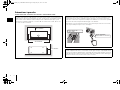
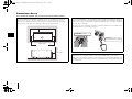
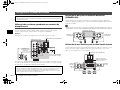
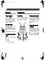
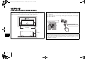
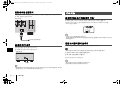
Precaution for use
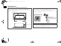
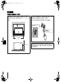
Read the supplied booklet “Safety Brochure” before using the unit.
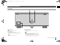
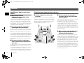
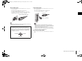
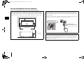
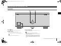
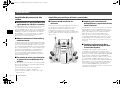
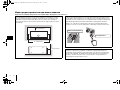
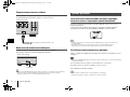
Install the unit in a well ventilated, cool, dry, clean place – away from direct sunlight,
heat sources, vibration, dust, moisture, and/or cold. Allow ventilation space of at
least 30 cm (11-3/4”) on the top, 20 cm (7-7/8”) on the left and right, and 20 cm
(7-7/8”) on the back of the unit.
30 cm (11-3/4”) or more
20 cm (7-7/8”) or more
20 cm (7-7/8”) or more
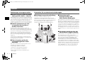
Since the unit adopts bare metallic speaker terminals, make sure keeping enough
space on the back of the unit. If the speaker terminals come into contact with metal
parts of the AV rack, etc., the unit will be shortened and damaged.
Also, never touch the speaker terminals when the unit is powered on since it may
cause an electrical shock.
The unit does not have volume controls. Make sure you connect a device with
volume control (such as a pre-amplifier) to the unit. If you connect a device without
volume control (such as a CD player) directly to the unit, the volume may become
excessively loud and result in damage to the unit or speakers.
Be careful with short circuits.
DO NOT TOUCH!
(when the unit is powered on)
MX-A5000_om_UCTKABGLVF.book Page i Thursday, April 4, 2013 5:28 PM

En 1
CONTENTS
Precaution for use . . . . . . . . . . . . . . . . . . . . . . . . . . . . . . . . . . . . . . . . . . . . . . . .i
Accessories . . . . . . . . . . . . . . . . . . . . . . . . . . . . . . . . . . . . . . . . . . . . . . . . . . . . . . 1
Features . . . . . . . . . . . . . . . . . . . . . . . . . . . . . . . . . . . . . . . . . . . . . . . . . . . . . . . . 2
Part names and functions . . . . . . . . . . . . . . . . . . . . . . . . . . . . . . . . . . . . . . . . 3
Front panel . . . . . . . . . . . . . . . . . . . . . . . . . . . . . . . . . . . . . . . . . . . . . . . . . . . . . . . . . . . . . . . . . . . . . . . . . . . . . . . . . . . . . . . . 3
Rear panel . . . . . . . . . . . . . . . . . . . . . . . . . . . . . . . . . . . . . . . . . . . . . . . . . . . . . . . . . . . . . . . . . . . . . . . . . . . . . . . . . . . . . . . . . 4
Connections . . . . . . . . . . . . . . . . . . . . . . . . . . . . . . . . . . . . . . . . . . . . . . . . . . . . . 6
Connecting speakers . . . . . . . . . . . . . . . . . . . . . . . . . . . . . . . . . . . . . . . . . . . . . . . . . . . . . . . . . . . . . . . . . . . . . . . . . . . . . . . 7
Connecting the power cable . . . . . . . . . . . . . . . . . . . . . . . . . . . . . . . . . . . . . . . . . . . . . . . . . . . . . . . . . . . . . . . . . . . . . . . 8
Turning on/off the unit . . . . . . . . . . . . . . . . . . . . . . . . . . . . . . . . . . . . . . . . . . . . . . . . . . . . . . . . . . . . . . . . . . . . . . . . . . . . . 8
Other functions . . . . . . . . . . . . . . . . . . . . . . . . . . . . . . . . . . . . . . . . . . . . . . . . . . 8
Turning off the unit automatically (auto-standby function) . . . . . . . . . . . . . . . . . . . . . . . . . . . . . . . . . . . . . . . . . . 8
Dimming the power indicator . . . . . . . . . . . . . . . . . . . . . . . . . . . . . . . . . . . . . . . . . . . . . . . . . . . . . . . . . . . . . . . . . . . . . . 8
Turning on the unit in conjunction with operating other devices (trigger function) . . . . . . . . . . . . . . . . . . . 9
Advanced speaker configuration . . . . . . . . . . . . . . . . . . . . . . . . . . . . . . . . 10
Using a speaker that supports bi-amp connection . . . . . . . . . . . . . . . . . . . . . . . . . . . . . . . . . . . . . . . . . . . . . . . . . . 10
Using two pairs of front speakers (SPEAKERS A/B) . . . . . . . . . . . . . . . . . . . . . . . . . . . . . . . . . . . . . . . . . . . . . . . . . . 10
Using three speakers for one channel (multi-speaker) . . . . . . . . . . . . . . . . . . . . . . . . . . . . . . . . . . . . . . . . . . . . . . 10
Appendix . . . . . . . . . . . . . . . . . . . . . . . . . . . . . . . . . . . . . . . . . . . . . . . . . . . . . . 11
Input-output signal path diagram . . . . . . . . . . . . . . . . . . . . . . . . . . . . . . . . . . . . . . . . . . . . . . . . . . . . . . . . . . . . . . . . . 11
Troubleshooting . . . . . . . . . . . . . . . . . . . . . . . . . . . . . . . . . . . . . . . . . . . . . . . . . . . . . . . . . . . . . . . . . . . . . . . . . . . . . . . . . . 12
Specifications . . . . . . . . . . . . . . . . . . . . . . . . . . . . . . . . . . . . . . . . . . . . . . . . . . . . . . . . . . . . . . . . . . . . . . . . . . . . . . . . . . . . . 13
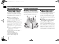
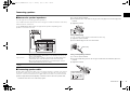
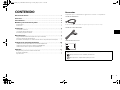
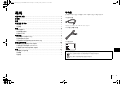
Accessories
Check that the following accessories are supplied with the product.
Power cable
*The supplied power cable varies depending on the region of purchase.
System control cable
Owner’s Manual
• Due to product improvements, specifications and appearance are subject to change without notice.
• indicates precautions for use of the unit and its feature limitations.
• indicates supplementary explanations for better use.
MX-A5000_om_UCTKABGLVF.book Page 1 Thursday, April 4, 2013 5:28 PM

2 En Features
Features
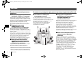
High-quality power amplifier
■ High output/high audio-quality
amplifier (150 W x 11 channels)
The unit provides an 11-channel power amplifier
featuring a three-stage Darlington current feedback
circuit, with a power supply that uses the same type of
toroidal transformer used in top-level hi-fi audio devices.
The gold-plated speaker connectors are also of the
highest quality, delivering high-grade sound.
■ Balance and unbalanced
connections are supported
Balanced (XLR) and unbalanced (RCA) input jacks are
provided on all channels, and can be selected
independently for each channel.
Balanced connections minimize the extraneous noise
that can arise in the cable connection between the unit
and the pre-amplifier, ensuring high-fidelity transmission
of the audio signal.
Unbalanced connections utilize ground-sensing to
achieve fidelity that is close to balanced transmission.
■ Chassis structure that maximizes
the potential of the unit's
performance
The chassis features a special structure that allows the
full potential of the high-quality power amplifier’s
potential to be revealed.
• Symmetrical power amplifier design
• Aluminum front panel and side panels
• Extremely stable feet utilizing the A.R.T.
(Anti-Resonance Technology)
Expandable to meet diverse needs
■ Freedom for speaker placement
Since power amplifiers of the identical specification are
provided for all 11 channels, you use the unit not only
for constructing a home theater setup of up to
11 channels but also for multi-room systems or any
other speaker configuration to meet your needs.
■ Support for bi-amp connections
and multi-speaker playback
The unit provides a channel selector function that lets
you utilize bi-amp connections or multi-speaker
connections without having to connect additional
cables from your pre-amplifier. For example, the CH.2
audio input could be output from both the CH.2 and
CH.3 speaker outputs to drive a bi-amp configuration
for high-quality sound, or the CH.1 (monaural) input
could be output from three speakers connected to CH.1
and CH.4 (L/R).
■ Switch the unit's power from your
pre-amplifier (trigger function)
The unit can switch its own power status in
synchronization with power switching operations on
another device that supports the trigger function, such
as an AV pre-amplifier (TRIGGER IN). The input signal
from the TRIGGER IN jack can also be output without
change in a cascade connection to switch the power of
another device such as a Yamaha subwoofer
(THROUGH OUT). In addition, another device can be
switched in synchronization when the power of the unit
is switched (TRIGGER OUT), allowing you to set up a
variety of systems with synchronized power switching.
Pre-amplifier
MX-A5000_om_UCTKABGLVF.book Page 2 Thursday, April 4, 2013 5:28 PM

Part names and functions En 3
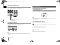
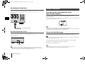
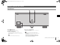
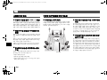
Front panel
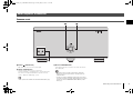
1 z (power) key
Turns on/off (standby) the unit (p.8).
2 Power indicator
Lights up when the unit is turned on.
If the indicator blinks, the protection circuitry has been
activated. For details, see “Troubleshooting” (p.12).
• You can dim the power indicator (p.8).
3 SPEAKERS A/B keys
Turns on /off the speakers connected to the CH.2 A/B
terminals (p.10).
• Both the speakers (A and B) are turned off by default. Press the
key to turn on the speakers you want to use.
• When using two pairs of the speakers connected to the CH.2
A/B terminals at the same time, be sure to use 8-ohm speakers
and set IMPEDANCE SELECTOR to the upper position (p.7).
Part names and functions
SPEAKERS
ON OFF
AB
21
3
MX-A5000_om_UCTKABGLVF.book Page 3 Thursday, April 4, 2013 5:28 PM

4 En Part names and functions
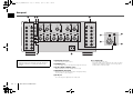
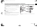
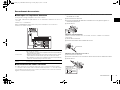
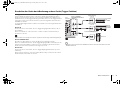
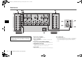
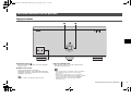
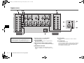
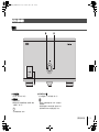
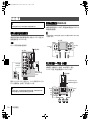
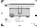
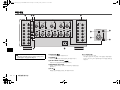
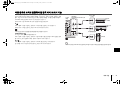
Rear panel
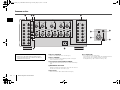
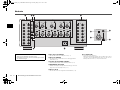
1 SPEAKERS terminals
For connecting to speakers (p.7).
2 TRIGGER jacks
For connecting to devices that support the trigger function (p.9).
3 AUTO POWER STANDBY switch
Enables/disables the auto-standby function (p.8).
4 IMPEDANCE SELECTOR
Changes the unit’s speaker impedance setting depending
on the speakers connected (p.7).
5 AC IN jack
For connecting the supplied power cable (p.8).
6 CH. SELECTOR
(CH.3, CH.4 and CH.6 only)
Selects the audio source input to the CH.3, CH.4 or CH.6
amplifier when applying a bi-amp connection (p.10) or a
multi-speaker connection (p.10).
AC IN
R
R
SPEAKERS
TRIGGER
INPUT
+12V
IN
THROUGH
OUT
BAL. UNBAL.
AUTO POWER
STANDBY
IMPEDANCE
SELECTOR
SELECTEUR
D’IMPEDANCE
OUT
OFF
ON
CH.6
CH.5
CH.5
CH.4
CH.3
CH.2
B
CH.2
A
CH.1
L
SPEAKERS
CH.6
CH.5
CH.4
CH.3
CH.2
B
CH.2
A
12V 0.1A
R
BAL. UNBAL.
CH.2
BAL. UNBAL.
CH.1
L
BAL. UNBAL.
CH.2
L
BAL. UNBAL.
CH.5
R
BAL. UNBAL.
CH.6
CH. SELECTOR
CH.5 CH.6
R
BAL. UNBAL.
CH.3
CH. SELECTOR
CH.2 CH.3
R
BAL. UNBAL.
CH.4
CH. SELECTOR
CH.1 CH.4
L
BAL. UNBAL.
CH.4
CH. SELECTOR
CH.1 CH.4
L
BAL. UNBAL.
CH.3
CH. SELECTOR
CH.2 CH.3
L
BAL. UNBAL.
CH.6
CH. SELECTOR
CH.5 CH.6
BAL. UNBAL.
CH. SELECTOR
3
4 5
6
7
8
9
11 2
Caution
• Remove the unit’s power cable from an AC wall outlet before
making any connections or operating the switches and/or
selectors.
MX-A5000_om_UCTKABGLVF.book Page 4 Thursday, April 4, 2013 5:28 PM

Part names and functions En 5
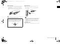
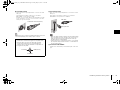
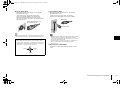
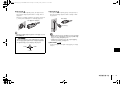
7 INPUT (XLR) jack
For connecting to a pre-amplifier with XLR output jacks (p.6).
To use the XLR jack, set the corresponding BAL/UNBAL
switch to “BAL”.
When connecting an XLR balanced cable, match the pins
and insert the “male” connector of the cable until you hear a
click.
• When disconnecting the cable from the unit, hold down the PUSH
button on the unit and then pull the connector out.
8 INPUT (RCA) jack
For connecting to a pre-amplifier with RCA output jacks
(p.6).
To use the RCA jack, set the corresponding BAL/UNBAL
switch to “UNBAL”.
• Remove the RCA short pins attached to the INPUT (RCA) jacks
before making connections. Be sure to keep them in a place
inaccessible to small children who may accidentally swallow
small parts.
• To protect against noise contamination, we recommend
attaching the RCA short pins when the INPUT (RCA) jacks are
not in use.
9 BAL/UNBAL switch
Switches between XLR input and RCA input for each channel
(p.6).
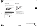
About the XLR jacks
• The pin assignments for the XLR jacks of the unit are shown
below. Before connecting an XLR balanced cable, refer to the
instruction manual of your pre-amplifier and verify that its XLR
output jacks are compatible with the pin assignments.
BAL. UNBAL.
XLR balanced cable (male)
3. COLD
2. HOT
1. GND
BAL. UNBAL.
RCA cable
RCA short pin
MX-A5000_om_UCTKABGLVF.book Page 5 Thursday, April 4, 2013 5:28 PM

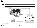
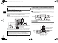
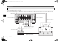
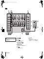
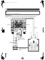
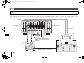
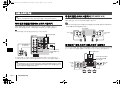
6 En Connections
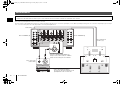
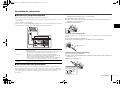
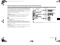
Connect a pre-amplifier and speakers to the unit.
To connect a pre-amplifier, use an XLR balanced cable (for balanced connection) or an RCA unbalanced cable (for unbalanced connection) for each channel depending on the
output jacks available on your pre-amplifier.
Connections
Caution
• Remove the unit’s power cable from an AC wall outlet before making any connections or operating the switches and/or selectors.
AC IN
R
R
SPEAKERS
TRIGGER
INPUT
+12V
IN
THROUGH
OUT
BAL. UNBAL.
AUTO POWER
STANDBY
IMPEDANCE
SELECTOR
SELECTEUR
D’IMPEDANCE
OUT
OFF
ON
CH.6
CH.5
CH.5
CH.4
CH.3
CH.2
B
CH.2
A
CH.1
L
SPEAKERS
CH.6
CH.5
CH.4
CH.3
CH.2
B
CH.2
A
12V 0.1A
R
BAL. UNBAL.
CH.2
BAL. UNBAL.
CH.1
L
BAL. UNBAL.
CH.2
L
BAL. UNBAL.
CH.5
R
BAL. UNBAL.
CH.6
CH. SELECTOR
CH.5 CH.6
R
BAL. UNBAL.
CH.3
CH. SELECTOR
CH.2 CH.3
R
BAL. UNBAL.
CH.4
CH. SELECTOR
CH.1 CH.4
L
BAL. UNBAL.
CH.4
CH. SELECTOR
CH.1 CH.4
L
BAL. UNBAL.
CH.3
CH. SELECTOR
CH.2 CH.3
L
BAL. UNBAL.
CH.6
CH. SELECTOR
CH.5 CH.6
BAL. UNBAL.
XLR
XLR
The unit (rear)
SPEAKERS (R) terminals SPEAKERS (L) terminals
INPUT (XLR or RCA) jacks
* Set the BAL/UNBAL switch for each channel
to “BAL” (XLR) or “UNBAL” (RCA)
depending on the connection type.
Pre-amplifier
Preout (XLR or RCA)
jacks
Subwoofer connections
* For details, refer to the instruction manuals
for your pre-amplifier and subwoofers.
Speaker connections (p.7)
MX-A5000_om_UCTKABGLVF.book Page 6 Thursday, April 4, 2013 5:28 PM

Connections En 7
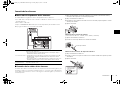
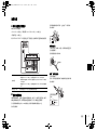
Connecting speakers
■ Note on the speaker impedance
The unit supports the following speaker impedance.
• CH.2 A/B: 4 or more (8 or more when using CH.2 A and CH.2 B at the same time)
• Other channels: 6 or more
Set the IMPEDANCE SELECTOR to the upper/lower position depending on the
speakers connected to the unit.
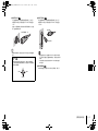
■ Connecting speaker cables
Speaker cables have two wires. One is for connecting the negative (-) terminal of the unit and
the speaker, and the other is for the positive (+) terminal. If the wires are colored to prevent
confusion, connect the black wire to the negative and the other wire to the positive terminal.
a Remove approximately 10 mm (0.40 in) of insulation from the ends of the speaker cable,
and twist the bare wires of the cable firmly together.
b Loosen the speaker terminal.
c Insert the bare wires of the cable into the gap on the side (upper left or bottom right) of the
terminal.
d Tighten the terminal.
Using a banana plug
(U.S.A., Canada, China, Taiwan and Australia models only)
a Tighten the speaker terminal.
b Insert a banana plug into the end of the terminal.
Using a Y-shaped lug connector
a Loosen the speaker terminal.
b Insert the Y-shaped lug connector into the groove between the knob and base part of the
terminal.
c Tighten the terminal.
Upper position
Select this option when your speaker system meets one of the followings.
• When connecting speakers with impedance of less than 8 (4 or more) to the
CH.2 A or CH.2 B terminal
• When using two pairs of speakers connected to the CH.2 A/B terminals at the
same time (be sure to use 8-ohm speakers for both CH.2 A and CH.2 B)
• When connecting speakers with impedance of less than 8 (6 or more) to
speaker terminals other than CH.2 A or CH.2 B
Lower position
(default)
Select this option when using speakers with impedance of 8
or more only.
aa
b
b
d
d
c
c
aa
b
b
Banana plug
aa
b
b
c
c
Use a Y-shaped lug
with the following size.
6.5 mm
(0.26 in)
or more
MX-A5000_om_UCTKABGLVF.book Page 7 Thursday, April 4, 2013 5:28 PM

8 En Other functions
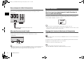
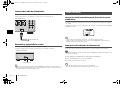
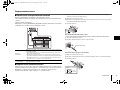
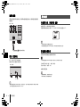
Connecting the power cable
After all the connections and switch operations are complete, connect the supplied
power cable to the unit and then to an AC wall outlet.
Turning on/off the unit
Press z (power) to turn on/off the unit.
When the unit is turned on, the power indicator lights up.
• When an external device is connected to the TRIGGER IN jack, the unit is set to standby mode after
z (power) is pressed. If you turn on the external device, the unit automatically turns on by the trigger
function (p.9).
Turning off the unit automatically
(auto-standby function)
The unit will automatically go into standby mode 8 hours after the unit is turned on.
To disable the auto-standby function, set the AUTO POWER STANDBY switch to “OFF”.
• The auto-standby function works even if playback is ongoing.
• When the system control cable is connected to the TRIGGER IN jack, the auto-standby function does not
work even if it is enabled.
Dimming the power indicator
You can dim the power indicator on the front panel of the unit.
• When an external device is connected to the TRIGGER IN jack, turn on it before performing the following
procedure.
a If the unit is turned on, press z (power) to turn off it.
b Press z (power) three times within 3 seconds.
The power indicator dims.
• To cancel the dimmer, perform the procedure again.
• If the power cable is unplugged, the dimmer will be canceled.
AC IN
CH.4
CH.3
CH.2
B
CH.2
A
L
BAL. UNBAL.
CTOR
H.4
L
BAL. UNBAL.
CH.3
CH. SELECTOR
CH.2 CH.3
L
BAL. UNBAL.
CH.6
CH. SELECTOR
CH.5 CH.6
To an AC wall outlet
The unit (rear)
z (power)
The unit (front)
Other functions
MX-A5000_om_UCTKABGLVF.book Page 8 Thursday, April 4, 2013 5:28 PM

Other functions En 9
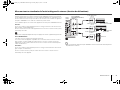
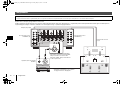
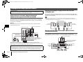
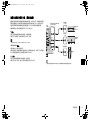
Turning on the unit in conjunction with operating other devices (trigger function)
The trigger function can control power of the unit in conjunction with operating other
devices or control power of other devices in conjunction with turning on/off the unit. If
you have a power amplifier or a Yamaha subwoofer that supports the trigger function,
you can use the trigger function by connecting your devices to the TRIGGER jacks with
the supplied system control cable.
Depending on the intended use, connect your device to one of the following TRIGGER
jacks.
IN jack:
For connecting a device that supports the trigger output function (such as a
pre-amplifier).
If you turn on/off your device, the unit will automatically turns on/off (standby).
• This function is available only when z (power) of the unit is on (pressed down).
THROUGH OUT jack:
This jack outputs signals input from the IN jack.
If you connect a device that supports the trigger input function (such as another power
amplifier), your device will automatically turn on/off in conjunction with turning on/off the
device connected to the IN jack.
OUT jack:
For connecting a device that supports the trigger input function (such as a subwoofer).
If you turn on/off (standby) the unit, your device will automatically turns on/off.
• To connect multiple devices to the TRIGGER jacks, you need to prepare commercially-available monaural
mini-plug cables.
R
TRIGGER
+12V
IN
THROUGH
OUT
BAL. UNBAL.
AUTO POWER
STANDBY
IMPEDANCE
SELECTOR
SELECTEUR
D’IMPEDANCE
OUT
OFF
ON
CH.5
12V 0.1A
R
CH.2
R
BAL. UNBAL.
CH.6
CH. SELECTOR
CH.5 CH.6
R
CH.3
CH. SELECTOR
CH.2 CH.3
TRIGGER
+12V
IN
THROUGH
OUT
OUT
12V 0.1A
The unit
(rear)
Another
power
amplifier
Trigger Out
(+12 V)
TRIGGER
(IN/THROUGH OUT/OUT) jacks
System connection
input
Pre-amplifier
(such as
CX-A5000)
Subwoofer
Trigger In
(+12 V)
MX-A5000_om_UCTKABGLVF.book Page 9 Thursday, April 4, 2013 5:28 PM

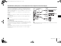
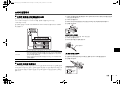
10 En Advanced speaker configuration
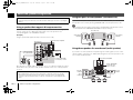
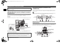
Using a speaker that supports bi-amp connection
If you want to use a speaker that supports bi-amp connection to have more high-quality
sounds, change the CH. SELECTOR setting and connect the speaker to the
corresponding pair of the SPEAKERS terminals.
(Example)
Using a speaker that supports bi-amp connection for CH.2 (R)
By setting the CH. SELECTOR for CH.3 (R) to “CH.2”, CH.2 (R) input signals are output
from both the CH.2 (R) and CH.3 (R) speaker terminals. In this case, CH.3 (R) input is
not used.
Using two pairs of front speakers (SPEAKERS A/B)
If you connect two pairs of front speakers to the CH.2 A/B terminals, you can switch the
front speakers to be used by pressing SPEAKERS A/B on the front panel of the unit.
• When using two pairs of the speakers connected to the CH.2 A/B terminals at the same time, be sure to
use 8-ohm speakers and set IMPEDANCE SELECTOR to the upper position (p.7).
Using three speakers for one channel (multi-speaker)
If you want to use three speakers for reproducing CH.1 audio signals (such as center
channel signals), change the CH. SELECTOR setting and connect the speakers to the
CH.1 and CH.4 (L/R) terminals.
Advanced speaker configuration
Caution
• Remove the unit’s power cable from an AC wall outlet before making any connections or operating the
switches.
Caution
• Before making bi-amp connections, remove any brackets or cables that connect a woofer with a
tweeter. Refer to the instruction manual of the speakers for details. If you are not making bi-amp
connections, make sure that the brackets or cables are connected before connecting the speaker
cables.
R
R
SPEAKERS
TRIGGER
+12V
IN
THROUGH
OUT
BAL. UNBAL.
AUTO POWER
STANDBY
IMPEDANCE
SELECTOR
SELECTEUR
D’IMPEDANCE
OUT
OFF
ON
CH.6
CH.5
CH.5
CH.4
CH.3
CH.2
B
CH.2
A
CH.1
12V 0.1A
R
BAL. UNBAL.
CH.2
R
BAL. UNBAL.
CH.6
CH. SELECTOR
CH.5 CH.6
R
BAL. UNBAL.
CH.3
CH. SELECTOR
CH.2 CH.3
CH
CH. S
E
CH.1
R
CH.3
CH. SELECTOR
CH.2 CH.3
The unit (rear)
Input from pre-amplifier
CH.2 A (R) and
CH.3 (R) terminals
Set CH. SELECTOR
for CH.3 (R) to “CH.2”
CH.2
B
CH.2
A
CH.2
B
CH.2
A
The unit (rear)
CH.2 A/B (L)
terminals
CH.2 A/B (R)
terminals
CH.4
CH.2
CH.4
BAL. UNBAL.
CH.1
R
CH.4
CH. SELECTOR
CH.1 CH.4
L
CH.4
CH. SELECTOR
CH.1 CH.4
The unit (rear)
Set CH. SELECTOR
for CH.4 (R) and
CH.4 (L) to “CH.1”
Input from pre-amplifier
CH.4 (R)
terminal
CH.4 (L)
terminal
CH.1
terminal
MX-A5000_om_UCTKABGLVF.book Page 10 Thursday, April 4, 2013 5:28 PM

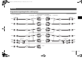
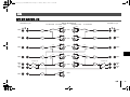
Appendix En 11
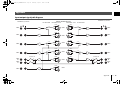
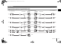
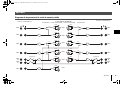
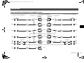
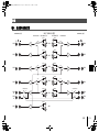
Input-output signal path diagram
Appendix
BAL
UNBAL
SPEAKER A/B
B
A
CH.3
CH.2
CH.4
CH.1
CH.6
CH.5
CH.6
CH.5
CH.4
CH.3
CH.2
CH.1
UNBAL
BAL
UNBAL
BAL
UNBAL
BAL
UNBAL
BAL
UNBAL
BAL
UNBAL
BAL
CH.6
CH.5
CH.4
CH.1
CH.3
CH.2
CH.6
CH.5
CH.4
CH.3
SPEAKER A/B
B
A
CH.1
BAL
UNBAL
BAL
UNBAL
BAL
UNBAL
BAL
UNBAL
CH.2
B
CH.2
A
CH.2
B
CH.2
A
CH.6
CH.5
CH.4
CH.3
R
L
R
R
R
R
R
L
L
L
L
L
INPUT (RCA/XLR) jacks
BAL/UNBAL switch CH SELECTORCH SELECTOR BAL/UNBAL switch
SPEAKERS (L) terminals
SPEAKERS (R) terminals
MX-A5000_om_UCTKABGLVF.book Page 11 Thursday, April 4, 2013 5:28 PM

12 En Appendix
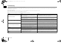
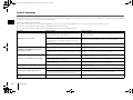
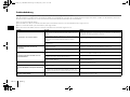
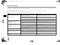
Troubleshooting
Refer to the table below when the unit does not function properly.
If the problem you are experiencing is not listed below or if the instructions below do not help, turn off the unit, disconnect the power cable, and contact the nearest authorized
Yamaha dealer or service center.
First, check the followings:
a The power cables of the unit and other devices (such as a pre-amplifier) are connected to AC wall outlets securely.
b The unit and other devices (such as a pre-amplifier) are turned on.
c The connectors of each cable are securely inserted in to jacks on each device.
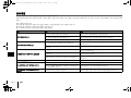
Problem Cause Remedy
The power does not turn on.
The protection circuitry has been activated three times
consecutively. When the unit is in this condition, the power
indicator on the unit blinks.
As a safety precaution, capability to turn on the power is disabled. Contact your
nearest Yamaha dealer or service center to request repair.
The internal microcomputer has frozen, due to an external electric
shock (such as lightning or excessive static electricity) or to a drop
in the power supply voltage.
Disconnect the power cable from the AC wall outlet and plug it again.
An external device is connected to the TRIGGER (IN) jack. Press down z (power) on the unit and then turn on the external device.
The power turns off (standby mode) immediately.
The unit was turned on while a speaker cable was shorted.
Twist the bare wires of each speaker cable firmly and reconnect to the unit and
speakers (p.7).
The unit was shorted because the speaker terminals come into
contact with metal parts of the AV rack, etc.
Keep enough space on the back of the unit (p.i).
The unit enters standby mode automatically.
The auto-standby function worked.
To disable the auto-standby function, set the AUTO POWER STANDBY switch to
“OFF” (p.8).
The protection circuitry has been activated because the volume of
the external device connected to the unit is too high.
Turn down the volume of the external device.
The protection circuitry has been activated because the
temperature inside of the unit is too high.
Install the unit in a well ventilated, place and allow enough ventilation space
around the unit (p.i).
No sound. The BAL/UNBAL switch setting is not correct. Change the BAL/UNBAL switch setting so that it matches the connections (p.6).
No sound is coming from a specific speaker.
The speakers connected to the CH.2 A/B terminals are turned off. Press SPEAKERS A/B to turn on the speakers (p.10).
The XLR balanced cable (or RCA unbalanced cable) connecting
the unit and pre-amplifier is defective, or the speaker cable
connecting the unit and speaker is defective.
If there is no problem with the connection, replace with another cable.
Another channel sound is coming from a specific
speaker.
The CH SELECTOR setting is not correct. Change the CH SELECTOR setting so that it matches your speaker system (p.10).
MX-A5000_om_UCTKABGLVF.book Page 12 Thursday, April 4, 2013 5:28 PM

Appendix En 13
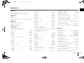
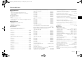
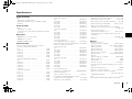
Specifications
Input jacks
•Audio
Analog RCA (Unbalance) x 11
Analog XLR (Balance) x 11 (1:GND, 2:HOT, 3:COLD)
Output jacks
•Audio
Speaker Out x 11 ch
(13 Terminals: CH.1, CH.2-A [L/R], CH.2-B [L/R], CH.3 [L/R] to
CH.6 [L/R])
Other jacks
• TRIGGER OUT x 1 (+12 V/0.1 A max.)
• TRIGGER IN x 1 (+12 V In)
• TRIGGER THROUGH OUT x 1
Audio Section
• Rated Output Power (2-channel driven)
(20 Hz to 20 kHz, 0.06% THD, 6 )
CH.1................................................................................ 170 W
CH.2 (L/R)....................................................................... 170 W
CH.3 (L/R)....................................................................... 170 W
CH.4 (L/R)....................................................................... 170 W
CH.5 (L/R)....................................................................... 170 W
CH.6 (L/R)....................................................................... 170 W
(20 Hz to 20 kHz, 0.06% THD, 8 )
CH.1................................................................................ 150 W
CH.2 (L/R)....................................................................... 150 W
CH.3 (L/R)....................................................................... 150 W
CH.4 (L/R)....................................................................... 150 W
CH.5 (L/R)....................................................................... 150 W
CH.6 (L/R)....................................................................... 150 W
(1 kHz, 0.9% THD, 8 )
CH.1................................................................................ 170 W
CH.2 (L/R)....................................................................... 170 W
CH.3 (L/R)....................................................................... 170 W
CH.4 (L/R)....................................................................... 170 W
CH.5 (L/R)....................................................................... 170 W
CH.6 (L/R)....................................................................... 170 W
• Rated Output Power (1-channel driven)
(1 kHz, 0.9% THD, 6 )
CH.1 ...........................................................................230 W/ch
CH.2 (L/R) ..................................................................230 W/ch
CH.3 (L/R) ..................................................................230 W/ch
CH.4 (L/R) ..................................................................230 W/ch
CH.5 (L/R) ..................................................................230 W/ch
CH.6 (L/R) ..................................................................230 W/ch
(1 kHz, 0.9% THD, 8 )
CH.1 ...........................................................................190 W/ch
CH.2 (L/R) ..................................................................190 W/ch
CH.3 (L/R) ..................................................................190 W/ch
CH.4 (L/R) ..................................................................190 W/ch
CH.5 (L/R) ..................................................................190 W/ch
CH.6 (L/R) ..................................................................190 W/ch
(1 kHz, 0.9% THD, 4 )
CH.2 (L/R) [U.K. and Europe models]........................290 W/ch
• Maximum Effective Output Power (1-channel driven, JEITA)
[China, Taiwan, Korea and Asia models]
(1 kHz, 10% THD, 6 )
CH.1 ...........................................................................280 W/ch
CH.2 (L/R) ..................................................................280 W/ch
CH.3 (L/R) ..................................................................280 W/ch
CH.4 (L/R) ..................................................................280 W/ch
CH.5 (L/R) ..................................................................280 W/ch
CH.6 (L/R) ..................................................................280 W/ch
(1 kHz, 10% THD, 8 )
CH.1 ...........................................................................230 W/ch
CH.2 (L/R) ..................................................................230 W/ch
CH.3 (L/R) ..................................................................230 W/ch
CH.4 (L/R) ..................................................................230 W/ch
CH.5 (L/R) ..................................................................230 W/ch
CH.6 (L/R) ..................................................................230 W/ch
• Dynamic Power (IHF)
1-channel driven (8/6/4/2 ) ......................190/250/350/500 W
• Damping Factor
All Channels, 1 kHz, 8 ....................................... 180 or more
• Input Sensitivity / Input Impedance
Unbalance (1 kHz, 100 W/8 ).............................. 1.0 V/47 k
Balance (1 kHz, 100 W/8 ) .................................. 2.0 V/47 k
• Maximum Input Signal
Unbalance (1 kHz, 0.5% THD, 8 ).....................1.3 V or more
Balance (1 kHz, 0.5% THD, 8 ) .........................2.6 V or more
• Frequency Response (10 Hz to 100 kHz)................... +0/-3 dB
• Total Harmonic Distortion (70 W/8 ) ............... 0.015% or less
• Signal to Noise Ratio (IHF-A Network)
(Input Shorted 1 k, Reference Level 150 W/8 )
......................................................................... 116 dB or more
• Residual Noise (IHF-A Network)
Speaker Out (Input Shorted)................................ 60 µV or less
• Channel Separation (Input 5.1 k Shorted , 1 kHz/10 kHz)
...................................................................... 90/75 dB or more
• Gain...............................................................................29.1 dB
General
• Power Supply
[U.S.A. and Canada models]..........................AC 120 V, 60 Hz
[Taiwan model]................................ AC 110 to 120 V, 50/60 Hz
[China model] .................................................AC 220 V, 50 Hz
[Korea model] .................................................AC 220 V, 60 Hz
[Australia model].............................................AC 240 V, 50 Hz
[U.K. and Europe models] .............................. AC 230 V, 50 Hz
[Asia model]....................................AC 220 to 240 V, 50/60 Hz
• Power Consumption
[U.S.A. and Canada models]..............................650 W/850 VA
[Korea model] .................................................................550 W
[Other models]................................................................650 W
• Standby Power Consumption ........................... 0.1 W (Typical)
• Maximum Power Consumption (All Channel driven, 10% THD)
[Taiwan and Asia models].............................................1500 W
• Power Consumption (No Signals) ...................... 75 W (Typical)
• Dimensions (W x H x D)
...................435 x 210 x 463.5 mm (17-1/8” x 8-1/4” x 18-1/8”)
* Including legs and protrusions
• Weight ...........................................................25.4 kg (56.0 lbs)
* Specifications are subject to change without notice.
MX-A5000_om_UCTKABGLVF.fm Page 13 Wednesday, May 1, 2013 4:08 PM

i Fr
Précautions à prendre
Lisez le livret fourni « Brochure sur la sécurité » avant d’utiliser l’unité.
Installez l’unité dans un endroit propre, sec, frais et bien ventilé, où il ne risque pas
d’être exposé directement à la lumière du soleil, à la poussière, à l’humidité, au froid
et/ou soumis à des vibrations. Veillez à disposer de suffisamment d’espace pour
assurer une ventilation adéquate : au moins 30 cm au-dessus de l’unité, 20 cm sur
les côtés et 20 cm à l’arrière.
30 cm minimum
20 cm minimum
20 cm minimum
Étant donné que l’unité est dotée de bornes d’enceinte à surfaces métalliques nues,
veillez à laisser un espace suffisant à l’arrière de l’unité. Si les bornes d’enceinte
entrent en contact avec les parties métalliques du bâti AV, un court-circuit se produit
au niveau de l’unité, risquant d’endommager cette dernière.
Par ailleurs, ne touchez jamais les bornes d’enceinte lorsque l’unité est sous tension,
car cela pourrait provoquer un choc électrique.
L’unité n’est pas dotée de commandes de volume. Assurez-vous de raccorder à
l’unité un appareil doté d’une commande de volume (par exemple, un préamplificateur).
Si vous raccordez un appareil sans commande de volume (par exemple, un lecteur
CD) directement à l’unité, le volume risque d’être assourdissant et des dommages
peuvent survenir au niveau de l’unité ou des enceintes.
Faites attention aux
courts-circuits.
NE PAS TOUCHER !
(lorsque l’unité est sous tension)
MX-A5000_om_UCTKABGLVF.book Page i Friday, May 10, 2013 11:43 AM

Fr 1
TABLE DES MATIÈRES
Précautions à prendre . . . . . . . . . . . . . . . . . . . . . . . . . . . . . . . . . . . . . . . . . . . . . i
Accessoires . . . . . . . . . . . . . . . . . . . . . . . . . . . . . . . . . . . . . . . . . . . . . . . . . . . . . . 1
Fonctions . . . . . . . . . . . . . . . . . . . . . . . . . . . . . . . . . . . . . . . . . . . . . . . . . . . . . . . 2
Noms de pièces et fonctions . . . . . . . . . . . . . . . . . . . . . . . . . . . . . . . . . . . . . . 3
Panneau avant . . . . . . . . . . . . . . . . . . . . . . . . . . . . . . . . . . . . . . . . . . . . . . . . . . . . . . . . . . . . . . . . . . . . . . . . . . . . . . . . . . . . . 3
Panneau arrière . . . . . . . . . . . . . . . . . . . . . . . . . . . . . . . . . . . . . . . . . . . . . . . . . . . . . . . . . . . . . . . . . . . . . . . . . . . . . . . . . . . . 4
Raccordements . . . . . . . . . . . . . . . . . . . . . . . . . . . . . . . . . . . . . . . . . . . . . . . . . . 6
Raccordements des enceintes . . . . . . . . . . . . . . . . . . . . . . . . . . . . . . . . . . . . . . . . . . . . . . . . . . . . . . . . . . . . . . . . . . . . . . 7
Raccordement du câble d’alimentation . . . . . . . . . . . . . . . . . . . . . . . . . . . . . . . . . . . . . . . . . . . . . . . . . . . . . . . . . . . . . 8
Mise sous/hors tension de l’unité . . . . . . . . . . . . . . . . . . . . . . . . . . . . . . . . . . . . . . . . . . . . . . . . . . . . . . . . . . . . . . . . . . . 8
Autres fonctions . . . . . . . . . . . . . . . . . . . . . . . . . . . . . . . . . . . . . . . . . . . . . . . . . 8
Mise hors tension automatique de l’unité (fonction de mise en veille automatique) . . . . . . . . . . . . . . . . . . 8
Réglage de la luminosité du témoin d’alimentation . . . . . . . . . . . . . . . . . . . . . . . . . . . . . . . . . . . . . . . . . . . . . . . . . 8
Mise sous tension simultanée de l’unité et d’appareils externes (fonction de déclencheur) . . . . . . . . . . . . 9
Configuration d’enceinte avancée . . . . . . . . . . . . . . . . . . . . . . . . . . . . . . . 10
Utilisation d’enceintes prenant en charge les connexions bi-amplificatrices . . . . . . . . . . . . . . . . . . . . . . . . . 10
Utilisation de deux paires d’enceintes avant (SPEAKERS A/B) . . . . . . . . . . . . . . . . . . . . . . . . . . . . . . . . . . . . . . . . 10
Utilisation de trois enceintes par voie (environnement multi-enceintes) . . . . . . . . . . . . . . . . . . . . . . . . . . . . . 10
Appendice . . . . . . . . . . . . . . . . . . . . . . . . . . . . . . . . . . . . . . . . . . . . . . . . . . . . . 11
Diagramme de la trajectoire du signal d’entrée/sortie . . . . . . . . . . . . . . . . . . . . . . . . . . . . . . . . . . . . . . . . . . . . . . 11
Guide de dépannage . . . . . . . . . . . . . . . . . . . . . . . . . . . . . . . . . . . . . . . . . . . . . . . . . . . . . . . . . . . . . . . . . . . . . . . . . . . . . . 12
Caractéristiques techniques . . . . . . . . . . . . . . . . . . . . . . . . . . . . . . . . . . . . . . . . . . . . . . . . . . . . . . . . . . . . . . . . . . . . . . . 13
Accessoires
Vérifiez que les accessoires suivants sont fournis avec le produit.
Câble d’alimentation
*Le câble d’alimentation fourni varie en fonction de la région d’achat.
Câble de commande système
Mode d’emploi
• En fonction des améliorations du produit, les caractéristiques techniques et illustrations peuvent être
modifiées sans préavis.
• signale les précautions à prendre concernant l’utilisation de l’unité et les limites de ses fonctions.
• signale des explications supplémentaires permettant une meilleure utilisation.
MX-A5000_om_UCTKABGLVF.book Page 1 Friday, May 10, 2013 11:43 AM

2 Fr Fonctions
Fonctions
Amplificateur de puissance haute
qualité
■ Amplificateur haute
puissance/haute qualité audio
(150 W x 11 voies)
L’unité est dotée d’un amplificateur de puissance 11 voies
muni d’une boucle de retour de courant Darlington à
trois niveaux, alimenté par un transformateur toroïdal
similaire à ceux utilisés dans les appareils audio Hi-Fi
haut de gamme. Les connecteurs d’enceinte plaqués or
sont également d’excellente qualité et produisent un
son d’une précision remarquable.
■ Prise en charge des connexions
symétriques et asymétriques
Des prises d’entrée symétriques (XLR) et asymétriques
(RCA) sont fournies sur toutes les voies et peuvent être
sélectionnées de manière indépendante pour chaque
voie.
Les connexions symétriques réduisent les bruits parasites
susceptibles d’être captés au niveau du raccordement
du câble entre l’unité et le préamplificateur, garantissant
ainsi une transmission haute fidélité du signal audio.
Les connexions asymétriques utilisent un détecteur au
sol pour obtenir une fidélité proche de la transmission
symétrique.
■ Structure de châssis exploitant
tout le potentiel de performances
de l’unité
Le châssis présente une structure spéciale permettant de
libérer tout le potentiel de l’amplificateur de puissance
haute qualité.
• Conception d’amplificateur de puissance symétrique
• Panneaux avant et latéraux en aluminium
• Pieds extrêmement stables utilisant la technologie A.R.T.
(Anti-Resonance Technology, technologie antirésonance)
Évolutivité pour répondre à divers besoins
■ Liberté de positionnement des
enceintes
Étant donné que les 11 voies sont dotées d’amplificateurs
de puissance partageant les mêmes caractéristiques
techniques, l’unité permet non seulement de configurer
un Home Cinéma 11 voies maximum mais aussi des
systèmes multipièces ou d’autres combinaisons
d’enceintes selon vos besoins.
■ Prise en charge de connexions
bi-amplificatrices et de la lecture
multi-enceintes
Grâce à la fonction de sélecteur de voies dont est dotée
l’unité, vous pouvez utiliser des connexions
bi-amplificatrices ou multi-enceintes sans avoir à
raccorder des câbles supplémentaires au niveau de
votre préamplificateur. Par exemple, l’entrée audio CH.2
peut être émise par les sorties des enceintes CH.2 et
CH.3 pour former une configuration bi-amplificatrice et
transmettre un son haute qualité, ou bien l’entrée CH.1
(mono) peut être émise par trois enceintes raccordées à
CH.1 et CH.4 (L/R).
■ Mise sous/hors tension de l’unité
depuis votre préamplificateur
(fonction de déclencheur)
La mise sous/hors tension de l’unité peut se faire de
manière synchronisée avec le dispositif de mise
sous/hors tension d’un autre appareil prenant en charge
la fonction de déclencheur, par exemple, un préampli
audio-vidéo (TRIGGER IN). Le signal d’entrée de la
prise TRIGGER IN peut également être restitué sans
dégradation dans un raccordement en cascade pour
mettre sous/hors tension un autre appareil, par exemple
un subwoofer Yamaha (THROUGH OUT). De plus, la
mise sous/hors tension d’un appareil externe peut se
faire de manière synchronisée avec la mise sous/hors
tension de l’unité (TRIGGER OUT), ce qui vous permet
de configurer plusieurs systèmes avec commutation
d’alimentation synchronisée.
Préamplificateur
MX-A5000_om_UCTKABGLVF.book Page 2 Friday, May 10, 2013 11:43 AM

Noms de pièces et fonctions Fr 3
Panneau avant
1 Bouton z (alimentation)
Met l’unité sous ou hors tension (veille) (p.8).
2 Témoin d’alimentation
S’allume lorsque l’unité est mise sous tension.
Si le témoin clignote, cela indique que le circuit de protection
a été activé. Pour plus d’informations, reportez-vous à la
section « Guide de dépannage » (p.12).
• Vous pouvez varier la luminosité du témoin d’alimentation (p.8).
3 Boutons SPEAKERS A/B
Activent/désactivent les enceintes raccordées aux bornes
CH.2 A/B (p.10).
• Les deux enceintes (A et B) sont désactivées par défaut.
Appuyez sur le bouton pour activer les enceintes que vous
souhaitez utiliser.
• Lorsque vous utilisez simultanément deux paires d’enceintes
raccordées aux bornes CH.2 A/B, veillez à utiliser des enceintes
8 ohms et à placer le IMPEDANCE SELECTOR en position
haute (p.7).
Noms de pièces et fonctions
SPEAKERS
ON OFF
AB
21
3
MX-A5000_om_UCTKABGLVF.book Page 3 Friday, May 10, 2013 11:43 AM

4 Fr Noms de pièces et fonctions
Panneau arrière
1 Bornes SPEAKERS
Pour le raccordement à des enceintes (p.7).
2 Prises TRIGGER
Pour le raccordement à des appareils prenant en charge la
fonction de déclencheur (p.9).
3 Commutateur AUTO POWER STANDBY
Active/désactive la fonction de mise en veille automatique
(p.8).
4 IMPEDANCE SELECTOR
Change le réglage de l’impédance d’enceinte de l’unité en
fonction des enceintes raccordées (p.7).
5 Prise AC IN
Pour raccorder le câble d’alimentation fourni (p.8).
6 CH. SELECTOR
(CH.3, CH.4 et CH.6 uniquement)
Sélectionne la source d’entrée audio de l’amplificateur CH.3,
CH.4 ou CH.6 lors de l’utilisation d’une connexion
bi-amplificatrice (p.10) ou multi-enceintes (p.10).
AC IN
R
R
SPEAKERS
TRIGGER
INPUT
+12V
IN
THROUGH
OUT
BAL. UNBAL.
AUTO POWER
STANDBY
IMPEDANCE
SELECTOR
SELECTEUR
D’IMPEDANCE
OUT
OFF
ON
CH.6
CH.5
CH.5
CH.4
CH.3
CH.2
B
CH.2
A
CH.1
L
SPEAKERS
CH.6
CH.5
CH.4
CH.3
CH.2
B
CH.2
A
12V 0.1A
R
BAL. UNBAL.
CH.2
BAL. UNBAL.
CH.1
L
BAL. UNBAL.
CH.2
L
BAL. UNBAL.
CH.5
R
BAL. UNBAL.
CH.6
CH. SELECTOR
CH.5 CH.6
R
BAL. UNBAL.
CH.3
CH. SELECTOR
CH.2 CH.3
R
BAL. UNBAL.
CH.4
CH. SELECTOR
CH.1 CH.4
L
BAL. UNBAL.
CH.4
CH. SELECTOR
CH.1 CH.4
L
BAL. UNBAL.
CH.3
CH. SELECTOR
CH.2 CH.3
L
BAL. UNBAL.
CH.6
CH. SELECTOR
CH.5 CH.6
BAL. UNBAL.
CH. SELECTOR
3
4 5
6
7
8
9
11 2
Attention
• Débranchez le câble d’alimentation de l’unité de la prise
secteur avant d’effectuer un raccordement ou d’utiliser les
commutateurs et/ou sélecteurs.
MX-A5000_om_UCTKABGLVF.book Page 4 Friday, May 10, 2013 11:43 AM
La pagina si sta caricando...
La pagina si sta caricando...
La pagina si sta caricando...
La pagina si sta caricando...
La pagina si sta caricando...
La pagina si sta caricando...
La pagina si sta caricando...
La pagina si sta caricando...
La pagina si sta caricando...
La pagina si sta caricando...
La pagina si sta caricando...
La pagina si sta caricando...
La pagina si sta caricando...
La pagina si sta caricando...
La pagina si sta caricando...
La pagina si sta caricando...
La pagina si sta caricando...
La pagina si sta caricando...
La pagina si sta caricando...
La pagina si sta caricando...
La pagina si sta caricando...
La pagina si sta caricando...
La pagina si sta caricando...
La pagina si sta caricando...
La pagina si sta caricando...
La pagina si sta caricando...
La pagina si sta caricando...
La pagina si sta caricando...
La pagina si sta caricando...
La pagina si sta caricando...
La pagina si sta caricando...
La pagina si sta caricando...
La pagina si sta caricando...
La pagina si sta caricando...
La pagina si sta caricando...
La pagina si sta caricando...
La pagina si sta caricando...
La pagina si sta caricando...
La pagina si sta caricando...
La pagina si sta caricando...
La pagina si sta caricando...
La pagina si sta caricando...
La pagina si sta caricando...
La pagina si sta caricando...
La pagina si sta caricando...
La pagina si sta caricando...
La pagina si sta caricando...
La pagina si sta caricando...
La pagina si sta caricando...
La pagina si sta caricando...
La pagina si sta caricando...
La pagina si sta caricando...
La pagina si sta caricando...
La pagina si sta caricando...
La pagina si sta caricando...
La pagina si sta caricando...
La pagina si sta caricando...
La pagina si sta caricando...
La pagina si sta caricando...
La pagina si sta caricando...
La pagina si sta caricando...
La pagina si sta caricando...
La pagina si sta caricando...
La pagina si sta caricando...
La pagina si sta caricando...
La pagina si sta caricando...
La pagina si sta caricando...
La pagina si sta caricando...
La pagina si sta caricando...
La pagina si sta caricando...
La pagina si sta caricando...
La pagina si sta caricando...
La pagina si sta caricando...
La pagina si sta caricando...
La pagina si sta caricando...
La pagina si sta caricando...
La pagina si sta caricando...
La pagina si sta caricando...
La pagina si sta caricando...
La pagina si sta caricando...
-
 1
1
-
 2
2
-
 3
3
-
 4
4
-
 5
5
-
 6
6
-
 7
7
-
 8
8
-
 9
9
-
 10
10
-
 11
11
-
 12
12
-
 13
13
-
 14
14
-
 15
15
-
 16
16
-
 17
17
-
 18
18
-
 19
19
-
 20
20
-
 21
21
-
 22
22
-
 23
23
-
 24
24
-
 25
25
-
 26
26
-
 27
27
-
 28
28
-
 29
29
-
 30
30
-
 31
31
-
 32
32
-
 33
33
-
 34
34
-
 35
35
-
 36
36
-
 37
37
-
 38
38
-
 39
39
-
 40
40
-
 41
41
-
 42
42
-
 43
43
-
 44
44
-
 45
45
-
 46
46
-
 47
47
-
 48
48
-
 49
49
-
 50
50
-
 51
51
-
 52
52
-
 53
53
-
 54
54
-
 55
55
-
 56
56
-
 57
57
-
 58
58
-
 59
59
-
 60
60
-
 61
61
-
 62
62
-
 63
63
-
 64
64
-
 65
65
-
 66
66
-
 67
67
-
 68
68
-
 69
69
-
 70
70
-
 71
71
-
 72
72
-
 73
73
-
 74
74
-
 75
75
-
 76
76
-
 77
77
-
 78
78
-
 79
79
-
 80
80
-
 81
81
-
 82
82
-
 83
83
-
 84
84
-
 85
85
-
 86
86
-
 87
87
-
 88
88
-
 89
89
-
 90
90
-
 91
91
-
 92
92
-
 93
93
-
 94
94
-
 95
95
-
 96
96
-
 97
97
-
 98
98
-
 99
99
-
 100
100


Yamaha MX-A5000 Manuale del proprietario
- Categoria
- Altoparlanti portatili
- Tipo
- Manuale del proprietario
in altre lingue
- English: Yamaha MX-A5000 Owner's manual
- français: Yamaha MX-A5000 Le manuel du propriétaire
- español: Yamaha MX-A5000 El manual del propietario
- Deutsch: Yamaha MX-A5000 Bedienungsanleitung
- русский: Yamaha MX-A5000 Инструкция по применению
- Nederlands: Yamaha MX-A5000 de handleiding
- dansk: Yamaha MX-A5000 Brugervejledning
- čeština: Yamaha MX-A5000 Návod k obsluze
- polski: Yamaha MX-A5000 Instrukcja obsługi
- svenska: Yamaha MX-A5000 Bruksanvisning
- Türkçe: Yamaha MX-A5000 El kitabı
- suomi: Yamaha MX-A5000 Omistajan opas