ECOFLAM MAX GAS 350 PR Operating Instructions Manual
- Categoria
- Camini
- Tipo
- Operating Instructions Manual
Questo manuale è adatto anche per

Technical data
Dati tecnici
Données techniques
Datos técnicos
Технические характеристики
Technische Daten
Operating instructions
Istruzioni per l’uso
Notice d’emploi
Manual de uso
Руководство по эксплуатации
Betriebsanleitung
Electric diagrams
Schemi elettrico
Schémas électrique
Esquemas eléctrico
Электрические схемы
Elektrische Diagramme
Spare parts list
Parti ricambi
Pièces de rechange
Piezas de recambio
Запчасти
Ersatzteilliste
GAS BURNERS
EN
IT
FR
ES
RU
MAX GAS 350 PR
MAX GAS 500 PR
MAX GAS 350 LN PR-MD TC SGT 230-50 BT330 3143401
MAX GAS 350 LN PR-MD TL SGT 230-50 BT330 3143402
MAX GAS 500 LN PR-MD TC SGT 400-50 BT330 3143406
MAX GAS 500 LN PR-MD TL SGT 400-50 BT330 3143407
www.ecoflamburners.com
DE
27-06-2016

Overview - Index of contents / Panoramica - Indice dei contenuti / Vue d'ensemble - Table des matières
Descripción - Sumario / Обзор - Содержание / Überblick - Inhaltsverzeichnis
Technical data
Dati tecnici
Données techniques
Datos técnicos
Технические характеристики
Technische Daten
EN
IT
FR
ES
RU
DE
3
Working diagrams
Campi di lavoro
Domaine de fonctionnement
Ámbito de funcionamiento
Рабочий диапазон
Arbeitsfeld
EN
IT
FR
ES
RU
DE
4
Dimensions
Dimensioni
Dimensions
Dimensiones
Размеры
Größe
EN
IT
FR
ES
RU
DE
5
Operating instructions for authorised specialists
EN 6 - 15
Istruzione per l’uso per il personale qualificato IT 16 - 25
Notice d’emploi pour l’installateur spécialiste FR 26 - 35
Instrucciones de montaje para el instalador especialista ES 36 - 45
Инструкция по эксплутации для
квалифицированных специалистов
RU 46 - 55
Βetriebsanleitung Für die autorisierte Fachkraft DE 56 - 65
Gas pressure diagrams
Diagrammi di pressione gas
Diagrammes de pression de gaz
Diagramas de presión de gas
Диаграммы давления газа
Voreinstellungsschemen
EN
IT
FR
ES
RU
DE
66 - 67
Electric diagrams
Schemi elettrico
Schémas électrique
Esquemas eléctrico
Электрические схемы
Elektrische Diagramme
EN
IT
FR
ES
RU
DE
68 - 71
Spare parts list
Parti di ricambio
Pièces de rechange
Piezas de recambio
Запчасти
Ersatzteilliste
EN
IT
FR
ES
RU
DE
72 - 74
Conformity declaration
Dichiarazione di conformità
Déclaration de conformite
Declaración de conformidad
Сертификат соответствия
Konformitätserklärung
EN
IT
FR
ES
RU
DE
75
DE
RU
ES
FR
IT
EN
420010537501
www.ecoflam-burners.com
2

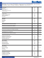
Technical data - Dati tecnici - Données techniques - Datos técnicos - Технические характеристики - Technische Daten
MAX GAS 350 PR MAX GAS 500 PR
Burner output
max/min kW -
kcal/h
Potenza bruciatore
max/min kW - kcal/h
Puissance du brûleur
max/min kW - kcal/h
Potencia del quemador
máx/mín kW - kcal/h
Мощность горелки
макс./мин., кВт - ккал/ч
Brennerleistung
max/min kW - kcal/h
350 100
500 120
301.000 86.000
430.000
103.200
Operation
2 stage
Funzionamento
2 stadio
Fonctionnement
2 allure
Funcionamiento
2 etapa
Moдифиkaция
2 ступень
Betrieb
2 Bühne
2 2
Regulating ratio
Rapporto di regolazione
Rapport de régulation Relación de regulación
Коэффициент
регулирования
Regelverhältnis 1:2
Fuel Combustibile Fuel
Combustible
Топливо
Kraftstoff
Natural Gas (L.C.V. 8.570 kcal/Nm
3
), LPG (L.C.V. 22.260
kcal/Nm
3
)
(G20) Hu = 10,35 kWh/m
3
- (G25) Hu = 8,83 kWh/m
3
(G31) Hu = 25,89 kWh/m
3
Emission class Classe di emissione Classe d’émission Tipo de emisión
Класс выделения
загрязняющих веществ
Emissionsklasse Standard Class 3 - GAS EN676 (<80mg/kWh)
Control box
Apparecchiatura di
controllo
Coffret de sécurité
Cajetín de seguridad
Блок управления и
безопасности
Feuerungsautomat
LAMTEC BT330
Gas train Rampa gas Rampe gaz Rampa de gas Газовая рампа Gasarmatur
GAS TRAIN TABLE - DIFFERENT MODELS /
CONFIGUATIONS
Gas connection Allacciamento gas Raccordement gaz
Conexión de gas
Подсоединение газа Gasanschluß Rp 20 3/4” - Rp 40 1”1/2 Rp 20 3/4” - Rp 40 1”1/2
Gas input pressure
Pressione di ingresso gas
Pression d’entrée du gaz
Presión de entrada
del gas
Давление газа на входе
Gaseingangsdruck
17 (20 Max Gas 500) - 500 mbar
(SEE GAS TRAIN MATCHING TABLE)
LPG input pressure Pressione di ingresso LPG
Pression d’entrée du gaz
propane
Presión de entrada
LPG
Давление LPG на входе LPG eingangsdruck
29 (37 Max Gas 500) - 500 mbar
(SEE GAS TRAIN MATCHING TABLE)
Air regulation
Air flap
Regolazione aria
Serranda dell'aria
Réglage de l’air
Volet d’air
Ajuste del aire
Válvula de aire
Настройка подачи
воздуха
Воздушная заслонка
Luftregulierung
Luftklappe
Schneider STE 4,5
B0.37/6-R
Schneider STE 4,5
B0.37/6-R
Flame monitor Rivelatore di fiamma Surveillance de flamme Vigilancia de llama
Контроль пламени
Flammenwächter
ionization ionization
Ignition transformer
Trasformatore
d'accensione
Allumeur Encendedor
Устройство розжига
Zündtransformator 1-Pole Electronic 1-Pole Electronic
Electric motor
rpm - watt
Motore elettrico
giri motore - watt
Moteur
rpm - watt
Motor
rpm - watt
Электродвигатель
об/мин - watt
Elektromotor
rpm - watt
2800 rpm
2800 rpm
300 W 550 W
Voltage
Tensione
Tension
Tensión
Напряжение
Spannung
230 V (230/400 V Max Gas 500) / 50 Hz
Power consumption
(operation)
Potenza elettrica
assorbita (Esercizio)
Puissance électrique
absorbée (en service)
Potencia eléctrica
absorbida (en
funcionamiento)
Потребляемая
электрическая
мощность: (при работе)
Elektrische Leistungs-
aufnahme
(Betrieb)
600 W 940 W
Weight
Peso
Poids
Peso Приблизительный вес
Gewicht
19,6 kg 23,5 kg
Protection level Classe di protezione Indice de protection Índice de protección
Класс электрозащиты
Schutzart IP55
Sound pressure
level dB(A)
Livello pressione
sonora dB(A)
Niveau presion
acoustique dB(A)
Nivel de presion
acústico dB(A)
Уровень шума, dB(A) Schalldruckpegel dB(A) 73 73
Ambient temp. for
storage
Temperatura ambiente di
stoccaggio
Température ambiante
de stockage
Temperatura ambiente
de almacenamiento
Температура хранения
Umgebungstemperatur
-20°…+70° C
Temperature for use
Temperatura
d’utilizzazione
Température d’utilisation
Temperatura ambiente
de utilización
Рабочая температура
Betriebstemperatur
-10°…+60° C
Overview / Panoramica / Vue d'ensemble / Descripción / Обзор / Überblick
DE
RU
ES
FR
IT
EN
420010537501
www.ecoflam-burners.com
3

4
www.ecoflam-burners.com
420010537501
EN
IT
FR
ES
RU
DE
Overview - Working diagrams / Panoramica - Curve / Vue d'ensemble - Domaine de fonctionnement / Descripción - Ámbito de funcionamiento /
Обзор - Рабочий диапазон / Überblick - Arbeitsfeld
100 200
200100 300 400
300 400 500 600
0
1
2
3
4
5
6
7
8
9
mbar
kW
kcal/h
x 1000
MAX GAS 350 PR-MD
MAX GAS 500 PR-MD
500
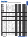
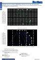
Working diagram
The working diagram shows
burner output as a function
of combustion chamber
pressure. It corresponds to
the maximum values
specified by EN 267
measured at the test fire
tube.The efficiency rating
of the boiler should be
taken into account when
selecting a burner.
Calculation of burner output:
QF =
Q
N
η
K
QF = Burner output (kW)
QN = Rated boiler
output (kW)
η
K
= Boiler efficiency (%)
Curva
Il campo di attività indica la
potenza del bruciatore in
funzione della pressione della
camera di combustione.
Corrisponde ai valori massimi
previsti dalla norma EN 267
misurati sul tubo della fiamma
di controllo. In occasione
della scelta del bruciatore
si deve tenere conto del
rendimento energetico
della caldaia.
Calcolo della potenza del
bruciatore:
QF =
Q
N
η
K
QF= potenza bruciata (kW)
QN= potenza nominale della
caldaia (kW)
η
K
= rendimento energetico
della caldaia (%)
Domaine de fonctionnement
Le domaine de fonctionnement
correspond aux valeurs
mesurées lors de
l’homologation. Elle correspond
aux valeurs max mesurées sur
tunnel d’essai d’après l’EN 267.
Pour le choix du brûleur, tenir
compte du rendement de la
chaudière.
Calcul de la puissance
calorifique:
QF =
Q
N
η
K
QF= Puissance calorifique (kW)
QN= Puissance nominale
chaudière (kW)
η
K
= Rendement chaudière (%)
Ámbito de funcionamiento
El ámbito de funcionamiento
corresponde a los valores
registrados en el momento
de la homologación.
Corresponde a los valores
máx medidos en el túnel de
ensayo según la EN 267.
Para la elección del
quemador, se ha de tener
en cuenta el rendimiento
de la caldera.
Cálculo de la potencia
calorífica:
QF =
Q
N
η
K
QF = Potencia calorífica (kW)
QN = Potencia nominal
de la caldera (kW)
η
K
= Rendimiento de la
caldera (%)
Рабочий диапазон
Рабочий диапазон
показывает
производительность горелки
в зависимости от давления в
топочной камере.
Он соответствует
максимальным значениям
согласно EN 267,
измеренным в контрольной
топочной камере.
При выборе горелки
необходимо учитывать
КПД котла.
Расчет тепловой мощности:
QF =
Q
N
η
K
QF = Тепловая мощность, кВт
QN= Номинальная мощность
котла, кВт
η
K
= КПД котла, %
Arbeitsfelder
Das Arbeitsfeld zeigt die
Bren- nerleistung in
Abhängigkeit vom
Feuerraumdruck. Es
entspricht den Maximalwerten
nach EN 267 gemessen am
Prüfflammenrohr.
Bei der Brennerauswahl ist
der Kesselwirkungsgrad zu
berücksichtigen.
Berechnung der Brennerleis-
tung:
QF =
Q
N
η
K
QF = Brennerleistung (kW)
QN = Kesselnennleistung
(kW)
η
K
= Kesselwirkungsgrad
(%)

C
I
B
A
L
N
E
D-D1
O
G
F
M
5
www.ecoflam-burners.com
420010537501
EN
IT
FR
ES
RU
DE
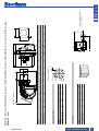
Overview - Dimensions / Panoramica - Dimensioni / Vue d'ensemble - Dimensions / Descripción - Dimensiones / Обзор - Размеры /
Überblick - Größe
X
Y
Z
Packaging
MAX GAS 350-500 PR
GAS TRAIN DIMENSIONS:
refer to GT manual
Pr
Ø r
Sr
MAX GAS 350-500 PR
Model
A B
C D D1 E
F G
I
L
M
N O
MAX GAS 350 PR 604
396
208 175
335
662
157 312
185/200 185/200
M8
62 101
MAX GAS 500 PR 604
396
208 175
335
662
157
312 185/200 185/200 M8
62 101
Model Ø a
Ø b
Ø c
d°..
MAX GAS 350 PR
167 262 283
45°
MAX GAS 500 PR
167 262 283
45°
d..°
Ø a
Ø b
Ø c
M
Boiler plate drilling
Model
X
Y
Z kg
MAX GAS 350 PR 796
1055
575
23,5
MAX GAS 500 PR 796
1055
575
29

6
www.ecoflam-burners.com
EN
420010537501
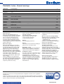
Contents - Index - General warnings
Important notes
MAX GAS 350-500 PR burners are
designed for the low-pollutant combustion
of natural gas and Liquefied Petroleum
Gas. The design and function of the
burners comply with standard EN676.
Assembly and commissioning must be
carried out only by authorised specialists
and all applicable guidelines and directives
must be observed.
Burner description
MAX GAS 350-500 PR are two-stage,
fully automatic, monoblock type burners.
The special design of the burner head
provides low-polluting combustion with
high efficiency. In line with testing as
defined by EN676, the values comply
with emissions class 3 (NOx<80mg/kWh)
Emissions values may differ, depending on
combustion chamber dimensions,
combustion chamber load and the firing
system (three-pass boilers, boilers with
reverse firing).
They are suitable for use with all heat
generators complying with EN 303 or for
use with hot air generators complying with
DIN 4794, and DIN 30697 within their
respective performance range.
Use for any other application requires the
approval of Ecoflam.
The following standards should be
observed in order to ensure safe,
environmentally sound and
energy-efficient operation:
EN 676
Forced-draught gas burners
EN 226
Connection of fuel oil and forced-draught
gas burners to a heat generator.
EN 60335-1, -2-102
Specification for safety of household and
similar electrical appliances, particular
requirements for gas burning appliances.
Installation location
The burner must not be operated in rooms
containing aggressive vapours (e.g. spray,
perchloroethylene, hydrocarbon
tetrachloride, solvent, etc.) or tending to
heavy dust formation or high air humidity.
Adequate ventilation must be provided at
the place of installation of the furnace
system to ensure a reliable supply with
combustion air.
Variations may arise as a result of local
regulations.
We can accept no warranty liability
whatsoever for loss, damage or injury
caused by any of the following:
- Inappropriate use.
- Incorrect assembly or repair by the
customer or any third party, including the
fitting of non-original parts.
Provision of the system and the
operating instructions
The firing system manufacturer must
supply the operator of the system with
operating and maintenance instructions on
or before final delivery. These instructions
should be displayed in a prominent
location at the point of installation of the
heat generator, and should include the
address and telephone number of the
nearest customer service centre.
Notes for the operator
The system should be inspected by a
specialist at least once a year. It is
advisable to take out a maintenance
contract to guarantee regular servicing.
Ecoflam burners have been designed and built in compliance with all current regulations
and directives.
All burners comply to the safety and energy saving operation regulations within the standard
of their respective performance range. The quality is guaranteed by a quality and management
system certified in accordance with ISO 9001:2008.
Overview Technical data 3
Working diagrams 4
Dimensions 5
Contents Index 6
General warnings 6
Burner description 7
Function General safety functions 8
LAMTEC control box 9
Installation Burner assembly 10
Electrical connection - Checks before commissioning 11
Start up Adjusting burner output 12
Air pressure switch adjustment - setting gas pressostat 13
Service Maintenance 14-15
Troubleshooting 15
Overview Gas pressure diagrams 66-67
Electrical diagrams 68-71
Spare parts list 72-74
Contents Conformity declaration 119

7
www.ecoflam-burners.com
EN
420010537501
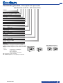
Scope of delivery
The burner is delivered in a modular system of
packagings i.e. separate set/box:
BBCH: Burner Body with Combustion Head
with flange.
- 1 bag including :- multilanguage technical manual.
- spanner.
- screws, nuts and washer.
GT: separate Gas Train
KIT & ACS are managed and delivered separately
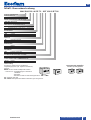
Contents - Burner description
KIT & ACS delivered separately
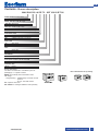
MAX GAS 350 LN PR TC SGT 230-50 BT330
MAX GAS Gas
RANGE NAME BY FUEL TYPE
MAX GAS 350350 kW
MODEL SIZE (Gas: kW; Oil: kg/h)
LN Low NOx Class 3 GAS EN676 (<80 mg/kWh)
- Standard Class 2-GAS EN676 (<120 mg/kWh)
EMISSION COMBUSTION TYPE
P 1 stage
PAB 2 stages
PR 2 stages progressive mechanical
OPERATION TYPE
TC Short head
TL Long head
HEAD TYPE
Natural gas
LPG LPG
FUEL
230-50 230 Volt, 50 Hz
ELECTRICAL SUPPLY TO THE SYSTEM
SGT Separate gas train
EQUIPMENT
BT330 Lamtec
CONTROL BOX

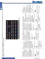
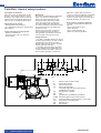
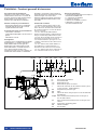
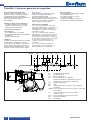
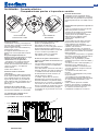
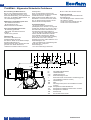
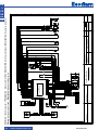
Function - General safety functions
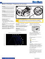
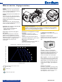
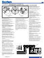
119 pBr
119.2
F6
1108106
119349
Y12 104F4150 Y13
M
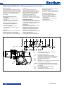
F4 Minimum gas pressure switch
F6 Air pressure switch
Y13 Main solenoid valve
Y12 Safety solenoid valve
1 Thermally-triggered safety shut-off valve
(installation by installer)
104 Gas pressure regulator
106 Filter
108 Gas ball valve (installation by installer)
119pBr Measuring point for gas outlet pressure
119 Measuring point for gas pressure in valve space
119.2 Air pressure measuring point
150 Butterfly valve
349 Servomotor
Description of functions
When the system is switched on for the
first time, after a power failure or safety
shutdown, after a lack of gas or after the
system has been out of operation for 24
hours, the pre-ventilation period begins.
During pre-purge period:
- blower pressure is monitored
- the combustion chamber is monitored for
flame signals.
At the end of the pre-purge period:
- ignition is switched on.
- main and safety valve are opened.
- burner starts.
Monitoring
The flame is monitored by an ionisation
probe. The probe is insulated and
fitted to the gas head and is routed
through the flame disc into the flame
zone. The probe must not have any
electrical contact with earthed parts.
The burner switches to lock-out if a short
circuit occurs between the probe and
the burner earth.
During burner operation, an ionised
zone is produced in the gas flame
through which a rectified current flows
from the probe to the burner head.
Safety functions
- If no flame is produced when the burner
is started (gas release), the burner will be
switched off at the end of the safety
period, lasting no more than 3 seconds,
and the gas valve will close.
- If the flame goes out during operation,
the gas supply is interrupted within one
second. A restart takes place. Once the
burner starts, operation is continued.
Otherwise, a safety lock-out occours.
- If there is a lack of air during reventilation
or operation, a safety lock-out occours.
- If there is a lack of gas, the burner does
not begin operation or switches off.
In the event of controller shutdown
- Controller thermostat interrupts heat
request.
- Gas solenoid valves close.
- Flame goes out.
- Burner motor switches off.
- Burner is ready for operation.
420010537501
EN
www.ecoflam-burners.com
8

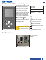
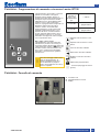
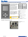
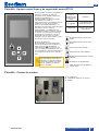
Function - Lamtec BT330 control and safety unit
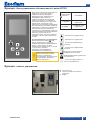
Function - Control panel
Pressing the
unlocking
button on the
unit for
.... causes ....
... 1 second ...
the control unit to
unlock.
... 4 seconds ...
he control unit to
unlock.
The control and safety unit BT 3xx controls
and monitors the forced draught burner.
The microprocessor-controlled program
sequence ensures the maximum
consistency of the cycle times involved,
regardless of fluctuations in the mains
voltage or ambient temperature. The
control and safety unit is designed to
detect power failures. Depending on the
parameter assignment, the unit either
switches to malfunction mode or goes into
the standby position if the power supply
falls below the mains voltage. In the
standby position, there is an automatic
restart as soon as the set threshold value
is exceeded by 105%.
Manual locking and unlocking
Using the reset button , the control and
safety unit can be locked manually
(interlocked) or unlocked, provided the unit
is connected to the mains power supply.
This function must not be confused with
automatic locking and fault
acknowledgement in case of an error.
!
Always switch off the power supply
before installing or removing the
control unit. Do not attempt to open
or carry out repairs on the control
unit.
Moves the cursor upwards.
Moves the cursor downwards.
Increases the marked value.
Reduces the marked value.
Modifies/Confirms the value shown.
Unlocks the control unit.
Red LED (flashes if a fault is
present).
A main switch I/0
B termal lock-out lamp
C display
AB
C
420010537501
EN
www.ecoflam-burners.com
9

10
www.ecoflam-burners.com
EN
420010537501
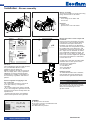
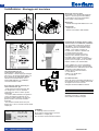
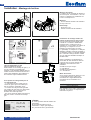
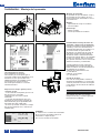
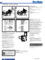
Installation
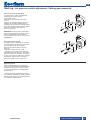
- Burner assembly
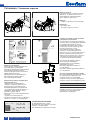
Burner blast tube insertion depth and
brickwork
Unless otherwise specified by the boiler
manufacturer, heat generators without a
cooled front wall require brickwork or
insulation 5 as shown in the illustration.
The brickwork must not protrude beyond
the leading edge of the blast tube, and
should have a minimum conical angle of
60°. Gap 6 must be filled with an elastic,
non-combustible insulation material. For
boilers with reverse firing, the minimum
burner tube insertion depth A as speci fied
in the boiler manufacturer’s instructions
must be observed.
On boilers the blast tube insertion depth
should be observed as per the boiler
manufacturer's instructions.
Reverse flame boiler :
A = 50-100 mm.
Three pass boilers :
A1 = 50-100 mm.
Exhaust system
To avoid unfavourable noise emissions,
right-angled connectors should not be
used on the flue gas side of the boiler.
Burner assembly
The burner is fixed by mean of connecting
flange and therefore to the boiler.
Installation:
• fix the flange to the boiler with
the screws.
Removal:
• loosen screw.
• pull the burner out of the boiler.
General regulations applying to the
gas connection
• The gas train must only be connected
to the gas mains by a recognised
specialist.
• The cross-section of the gas line should
be of a size designed to guarantee that the
gas flow pressure does not drop below the
specified level.
• A manual shut-off valve (not supplied)
must be fi tted upstream of the gas train.
Gas lines
When installing the gas lines and gas train,
the general EN676 directives and
guidelines must be observed.
EN676 compulsory kit and accessories in
order to comply to the safety regulations.
Additional accessories and kits shall be
installed by the installer in accordance to
the local safety regulations and codes of
practise.
LEGENDA
Pf: Back pressure of furnace
Pb: Pressure of burner (combustion head
+ complete gas train)
Pin: Minimum inlet pressure
For operation with Lique fied Petroleum
Gas, it is necessary to order the kit and
follow the instructions given in the
specific manual.
LPG TRANSFORMATION
KITLPG-MAXGAS...
1
2
–
+
A
A1

11
www.ecoflam-burners.com
EN
420010537501
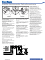
A
A
2,5
3
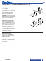
IONIZATION
PROBE
IGNITION
ELECTRODE
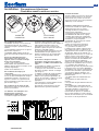
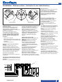
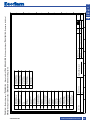
Electrical connection
The electrical installation and connection
work must only be carried out by an
authorised electrical specialist.
All applicable rules and regulations must
be observed.
The electrical installation should include a
type A circuit breaker.
The applicable guidelines and
directives must be observed, as well as
the electrical circuit diagram supplied
with the burner!
• Check to ensure that the power supply
voltage is as specified in the electric
diagram and in data plate.
• Burner fuse: 5 A.
Electrical connection (plug-in)
It must be possible to disconnect the
burner from the mains using an
omnipolar shutdown device complying
with the standards in force. The burner
and heat generator (boiler) are connected
to the terminal block of the cabinet (fig.1).
Connecting the gas train
Connect the gas train to the plugs on the
burner.
The burners are produced with
connections suitable for power supply
400 V three-phase.
The burners with electric motors of an
output lower or equal to 7,5 kW can be
adapted to 220-230 V (please follow the
Checks before commissioning
The following must be checked before
initial commissioning:
• That the burner is assembled in
accordance with the instructions given
here.
• That the burner is pre-set in accordance
with the values in the adjustment table.
• Setting the combustion components.
• The heat generator must be ready for
operation, and the operating regulations
for the heat generator must be observed.
• All electrical connections must be correct.
• The heat generator and heating system
must be filled with water and the
circulating pumps must be in operation.
• The thermostats, pressure regulator, low
water detectors and any other safety or
limiting devices that might be fitted must
be connected and operational.
• The exhaust gas duct must be
unobstructed and the secondary air
system, if available, must be operational.
• An adequate supply of fresh air must be
guaranteed.
• The heat request must be available.
• Sufficient gas pressure must be
available.
• The fuel supply lines must be assembled
correctly, checked for leaks and bled.
• A standard-compliant measuring point
must be available, the exhaust gas duct up
to the measuring point must be free of
leaks to prevent anomalies in the
measurement results.
Position of electrodes
Setting the ionisation probe and
ignition electrode: see diagram
Always check the position of the
electrodes after service or substitution
or assembly of LPG kit as wrong position
might cause ignition problem.
instructions on the backside); motors with
higher output can only work 380-400 V
three-phase.
In case of request of burners different from
the above mentioned standard, it is
recommended to make specific mention in
the order.
Instructions: how to adapt electric
motors of an output lower or equal to
7,5 kW to 220-230 V power supply
It is possible to change the voltage of the
burner by operating as follows:
1. change the connection inside the
electric box of the motor, from star to delta
(see picture 3);
2. change the setting of the thermal relay,
referring to the absorption values indicated
in the motor nameplate. If necessary,
replace the thermal relay with another one
of suitable scale.
This operation is not possible on motors
above 7.5 kW.
For more information, please contact the
Ecoflam staff.
HLB
HLF
T
P
STAB
25 26
P
T
STC
Q
50 Hz 400V
P
T
STS
T
N
S
PE
R
NTR S 9865 7 131110 121 2 3 4
1
Installation
- Electrical connection - Checks before commissioning
230V
400V

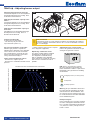
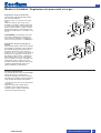
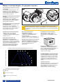
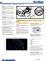
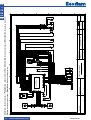
Gas pressure diagrams in appendix
Minimum gas pressure required are
indicated in the diagrams in the appendix.
These values have been determined in
our test labs and are useful for the first
switch-on as final setting must be done
using a combustion analyzer.
How to read and adjust the values:
- determine the output required
- determine the combustion chamber back-
pressure
- read the minimum gas pressure required
in the diagrams in appendix.
Optimising combustion values
The factory setting shall be modified
according to the output requeired.
The diagrams of air/head setting
that are available in the appendix
of this manual are a guide for ensuring
that the burner functions as well as
possible.
N.B. observe the minimum required
flue gas temperature specified by the
boiler manufacturer and the requirements
demanded of flue gas ducts for avoiding
condensation.
Adjustment of gas solenoid valve
Refer to the gas train manual for the gas
setting of the gas train selected.
head gas pressure (on elbow) (mbar)
head position
air damper position
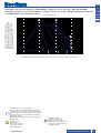
Warning: the pre-calibration values have
been determined on EN676 test combu-
stion chambers in ideal conditions, and
are useful for the first switch-on but must
be checked and corrected with calibration
for the individual system.
Example in figure:
Power required by the generator: 380 kW.
Pressure envisaged in combustion cham-
ber: 3.5 mbar. Combustion head chamber:
2.5 (between 2 and 3). Gas pressure in
head: 13 mbar.
pressure in the combustion chamber (mbar)
output (kW)
-1,0
0,0
1,0
2,0
3,0
4,0
5,0
6,0
7,0
8,0
9,0
10,0
50 100 150 200 250 300 350 400 450 500 550 600
16
15 14 13
12,5
12
11,5
1
90°
2
90°
3
90°
4
90°
5
90°
EXAMPLE OF PRE-CALIBRATION MAX GAS 500 PR
Start up
- Adjusting burner output
!
Risk of air blast!
Continuously check CO, CO
2
and soot emissions when adjusting the output of
the burner. Optimise combustion values in the event of CO formation. CO must
not exceed 50 ppm.
Firing head setting (B).
To act on the screw in fi gure:
• turn Allen key till you reach the
requested value (index 1-5).
+
-
1
1 LIATED
B
420010537501
EN
www.ecoflam-burners.com
12
Adjusting the maximum air flow rate
Air and Gas adjustment are accomplished
through BT3XX parameters setting. Refer
to BT3XX manual attached.
Adjusting the minimum capacity of the
burner
Air and Gas adjustment are accomplished
through BT3XX parameters setting. Refer
to BT3XX manual attached.
Adjusting the intermediate capacity of
the burner
Gas adjustment is accomplished through
BT3XX parameters setting. Refer to
BT3XX manual attached.

13
www.ecoflam-burners.com
EN
420010537501
Start up
- Air pressure switch adjustment - Setting gas pressostat
Operating check
Flame monitoring must be checked for
safety as part of initial commissioning and
also after servicing or if the system has
been out of operation for any significant
period of time.
- Start attempt with gas ball valve closed:
the automatic combustion control unit must
switch to gas shortage or malfunction after
the end of the safety period.
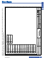
Air pressure switch calibration
The air pressure switch is provided for
monitoring the pressure of the
combustion air fan.
Unscrew screws A and B and remove
cover C.
After the air and gas setting you have to
calibrate the air switch with the burner
working on the low flame by slowly turning
the relative knob clockwise until the burner
locks out. Read the value and then
decrease it by 15%.
WARNING: the air pressure switch shall
prevent the air pressure to go below 85%
from the adjustment value in order to
prevent the CO in the fumes to exceed 1%
(10000 ppm).
Min gas pressure switch
The gas pressure switch has the function
to check that the gas pressure before the
gas valve does have the minimum
pressure to make the burner running
correctly.
Unscrew off and remove cover M.
- Set knob N to a value equal to 60% of
gas nominal feed pressure (i.e. for natural
gas nom. pressure = 20 mbar, set knob to
a value of 12 mbar; for LPG nom. pressure
of G30/G31- 30/37 mbar, set knob to a
value of 18 mbar). Screw up cover M.
0,4
0,6
0,9
3,0
1,5
2,1
1,8
2,4
2,7
1,2
A
B
C
D
2
,5
5
10
15
5
0
2
5
3
5
30
40
45
2
0
I
L
M
N

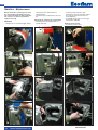
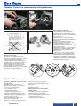
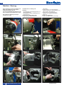
Service - Maintenance
Burner and boiler servicing must only
be carried out by qualified personell.
The system operator is advised to take
out a service contract to guarantee
regular servicing.
Attention
• Disconnect the electrical supply before
carrying out any maintenance or
cleaning work.
• The blast tube and firing head may be
hot.
Checking the exhaust gas temperature
• Check the flue gas temperature at
regular intervals.
• Clean the boiler if the flue gas
temperature is more than 30°C above
the value measured at the time of
commissioning.
• To simplify the check, use a flue gas
temperature indicator.
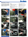
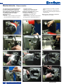
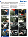
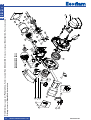
Removing firing head
• See pictures in the order.
1
23
4
5
6
77
8
9
10 11 12
420010537501
EN
www.ecoflam-burners.com
14

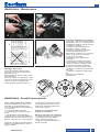
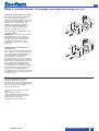
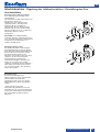
Fan assembly
Observe the positioning diagram above
when replacing the motor and blower
wheel. The inside flange A of the blower
wheel must be fitted at the same level as
the equipment plate B. Insert a straight
edge between the wing of the blower wheel
and set A and B to the same height, tighten
the set screw on the blower wheel
(maintenance position 1).
Maintenance on the burner
• Check gas supply components (tubes,
lines) and their connections for leaks
or signs of wear, replace if necessary.
• Check electrical connections and
connection cables for damage,
replace if necessary.
• Check gas filter, clean or replace as
necessary.
• Clean fan wheel and housing and
check for damage.
• Check and clean the mixing unit.
• Check ignition electrodes block,
readjust or replace as necessary.
• Start burner, check flue gas data,
correct burner settings if necessary.
• Check the setting for air pressure
switch and gas pressostat.
• Check the gas train settings.
• Carry out an operating check.
A
A
2,5
3
Service - Maintenance
13
14 15
420010537501
EN
www.ecoflam-burners.com
15
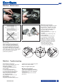
Fault diagnosis and repair
In the event of a malfunction, first check
that the prerequisites for correct
operation are fu llfilled:
1. Is the system connected to the
power supply?
2. Is there any gas pressure?
3. Is the gas shut-off valve open?
4. Are all control and safety devices,
such as the boiler thermostat, low
water level detector, limit switch,
etc. adjusted correctly?
If the malfunction persists, use the
following table.
It is not permitted to repair any
components relevant to safety. These
components must be replaced by parts
with the same order number.
Only use original spare parts.
NB: after each operation:
• under normal operating conditions
(doors closed, hood fitted, etc.), check
combustion and check the individual
lines for leaks.
• Record the results in the relevant
documents.
Service - Troubleshooting

Contenuti generali - Indice - Avvertenze generali
Avvertenze importanti
I bruciatori MAX GAS 350-500 PR sono
progettati per la combustione di gas
naturale e di gas propano, con basse
emissioni inquinanti. I bruciatori sono
conformi alla norma EN 676, dal punto di
vista della progettazione e del
funzionamento. Montaggio, messa in
funzione e manutenzione devono essere
eseguiti esclusivamente da personale
tecnico autorizzato, nel rispetto delle
direttive e delle prescrizioni in vigore.
Descrizione del bruciatore
I bruciatori MAX GAS 350-500 PR sono
bistadio, a funzionamento completamente
automatico in esecuzione monoblocco.
La costruzione speciale della testa di
combustione permette di ottenere una
combustione con un debole tasso di ossidi
di azoto e un coefficiente di rendimento
elevato. I valori delle emissioni
corrispondono alla classe 3, come definita
da EN676 (NOx<80mg/kWh).
A seconda della geometria del focolare,
della carica e del sistema di combustione
(caldaia a tre percorsi, caldaia a
combustione inversa), si possono
riscontrare valori di emissione diversi.
Sono adatti per l'allestimento di tutti i
generatori di calore conformi alla norma
EN 303 o degli aerotermi secondo DIN
4794 o DIN 30697 nell'ambito del rispettivo
range di potenza. Per ogni altro utilizzo è
necessaria l'autorizzazione della Ecoflam.
Al fine di garantire un funzionamento
sicuro, non inquinante ed a basso
consumo energetico, è necessario
rispettare le seguenti norme:
EN 676
Bruciatore di gas ad aria soffiata
EN 226
Allacciamento di bruciatori di gasolio a
nebulizzazione e bruciatori di gas ad
aria soffiata su generatori di calore
EN 60335-1, -2-102
Sicurezza degli apparecchi elettrici per uso
domestico, norme particolari per gli
apparecchi con combustione a gas.
Luogo di installazione
Il bruciatore non dev'essere messo in
funzione in locali in cui siano presenti
vapori aggressivi (ad es. lacca per capelli,
percloroetilene, tetracloruro di carbonio),
notevole accumulo di polvere o forte
umidità dell'aria (ad es. lavanderie).
Una adeguata ventilazione deve essere
fornita nel locale dell’installazione in modo
da garantire le condizioni per una buona
combustione.
Si possono riscontrare scostamenti
dovuti ad eventuali normative locali.
Si esclude qualsivoglia responsabilità
per eventuali danni derivanti dalle
seguenti cause:
- utilizzo non conforme.
- montaggio difettoso e/o riparazione a
cura dell'acquirente o terzi, ivi inclusa
l'applicazione di elementi di origine
estranea.
Consegna e istruzioni per l'uso
Il costruttore dell'impianto di combustione
è tenuto a consegnare al gestore
dell'impianto, al più tardi all'atto della
consegna dello stesso, le istruzioni per
l'uso e la manutenzione. Queste istruzioni
devono essere appese nel locale di
installazione del generatore termico in
modo ben visibile. Devono essere indicati
l'indirizzo ed il numero telefonico del punto
di assistenza più vicino.
Avvertenza per il gestore
L'impianto dev'essere controllato almeno
una volta l'anno da un tecnico specia-
lizzato. Al fine di garantire un'esecuzione
regolare, si suggerisce di stipulare un
contratto per la manutenzione
dell'impianto.
I bruciatori Ecoflam sono stati progettati e costruiti nel rispetto delle normative e direttive correnti.
Tutti i bruciatori rispondono alle normative sulla sicurezza e sul risparmio energetico nel limite del
campo di lavoro dichiarato.
La qualità del prodotto è garantita dal sistema di certificazione in base alla norma ISO 9001:2008.
Panoramica Dati tecnici 3
Curve di lavoro 4
Dimensioni d’ingombro 5
Contenuti generali Indice 16
Avvertenze generali 16
Descrizione del bruciatore 17
Funzione Funzioni generali di sicurezza 18
Programmatore di comando e sicurezza LAMTEC 19
Installazione Montaggio del bruciatore 20
Connessione elettrica - Controlli da eseguire prima della messa in funzione 21
Messa in funzione Regolazione del bruciatore 22
Regolazione dei pressostati aria e gas 23
Assistenza Manutenzione 24-25
Possibili inconvenienti 25
Panoramica Diagrammi di pressione gas 111-112
Schemi elettrici 113-116
Parti di ricambio 117-118
Contenuti generali Dichiarazione di conformità 119
420010537501
IT
www.ecoflam-burners.com
16

Imballaggio
Il bruciatore è consegnato con un sistema modulare di
imballo (scatole separate):
BBCH: Brucitore completo con testa di combustione e
flangia.
- 1 sacchetto : - manuale tecnico in multilingue.
- chiave esagonale.
- viti, dadi e rosette.
GT: Rampa Gas separata
KIT & ACS ordinabili e consegnati separatamente
KIT & ACS ordinabili e
consegnati separatamente
Contenuti generali - Descrizione del bruciatore
420010537501
IT
www.ecoflam-burners.com
17
MAX GAS 350 LN PR TC SGT 230-50 BT330
MAX GAS Gas
NOME
MAX GAS 350350 kW
MODELLO (Gas: kW; Oil: kg/h)
LN Low NOx Classe 3 GAS EN676 (<80 mg/kWh)
- Standard Classe 2-GAS EN676 (<120 mg/kWh)
EMISSIONI
P 1 stadio
PAB 2 stadio
PR 2 stadi progressivo meccanico
TIPO DI FUNZIONAMENTO
TC Testa corta
TL Testa lunga
TIPO TESTA
Gas Naturale
LPG Gas Propano
COMBUSTIBILE
230-50 230 Volt, 50 Hz
TENSIONE DI ALIMENTAZIONE
SGT Rampa gas separata
EQUIPAGGIAMENTO
BT330 Lamtec
APPARECCHIATURA DI CONTROLLO

Funzione - Funzioni generali di sicurezza
420010537501
IT
www.ecoflam-burners.com
18
Descrizione del funzionamento
Alla prima messa sotto tensione, dopo
un'interruzione di corrente e una fase di
messa in sicurezza, dopo un'interruzione
di gas o dopo un arresto di 24 ore,
comincia un tempo di preventilazione.
Durante il tempo di preventilazione:
- la pressione dell'aria viene monitorata.
- controllo della presenza di eventuali
segnali di fiamma anomali.
Al termine del tempo di preventilazione
- l'accensione è inserita.
- l'elettrovalvola principale e di sicurezza è
aperta.
- il bruciatore si avvia.
Sorveglianza
La fiamma viene monitorata da una sonda
di ionizzazione. La sonda è montata in
modo isolato sulla testa del gas ed è
diretta attraverso il disco fiamma nella
zona della fiamma. La sonda non deve
avere alcun contatto elettrico con
componenti messi a terra. Se compare un
cortocircuito tra la sonda e la massa del
bruciatore, il bruciatore entra in stato di
anomalia. Durante il funzionamento, nella
fiamma del gas si crea una zona
ionizzata, attraverso la quale circola una
corrente raddrizzata dalla sonda verso il
boccaglio.
Funzioni di sicurezza
- Se all'avvio del bruciatore (rilascio del
gas) non si forma la fiamma, il bruciatore
viene arrestato al termine di un intervallo
di sicurezza di max. 3 secondi, la valvola
del gas si chiude.
- In caso di anomalia della fiamma
durante il funzionamento, l'alimentazione
del gas si interrompe nella frazione di un
secondo. Viene avviata una nuova messa
in funzione. Se il bruciatore si avvia, il
ciclo di funzionamento prosegue. In caso
contrario si instaura una fase di messa in
sicurezza.
- In caso di mancanza d'aria durante la
preventilazione o il funzionamento, si
instaura una fase di messa in sicurezza.
- In caso di mancanza di gas, il bruciatore
non si mette in funzione e/o si arresta.
Arresto di regolazione
- Il termostato di regolazione interrompe la
richiesta di riscaldamento.
- Le valvole gas si chiudono.
- La fiamma si spegne.
- Il motore del ventilatore si ferma
- Il bruciatore è pronto per il
sucessivo funzionamento.
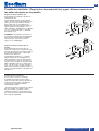
119 pBr
119.2
F6
1108106
119349
Y12 104F4150 Y13
M
F4 Pressostato gas minima
F6 Pressostato aria
Y13 Elettrovalvola gas
Y12 Elettrovalvola gas di sicurezza
1 Valvola di sicurezza ad azionamento termico (deve
essere montata dall'installatore).
104 Regolatore di pressione gas
106 Filtro
108 Valvola di arresto del gas (deve essere montata dal
l'installatore).
119pBr Punto di misurazione della pressione del gas al
l'uscita della valvola.
119 Punto di misurazione della pressione del gas tra le
valvole.
119.2 Air pressure measuring point
150 Valvola a farfalla
349 Servomotore

420010537501
IT
www.ecoflam-burners.com
19
L'azionamento del
pulsante di
sblocco del
programmatore
per...
.... causa ....
... 1 secondo ...
lo sblocco del
programmatore.
... 4 secondi ...
il blocco del
programmatore.
Il programmatore di comando e sicurezza
gas BT 3xx comanda e sorveglia il
bruciatore ad aria soffiata. Grazie al
programma gestito dal microprocessore si
ottengono tempi estremamente stabili,
indipendentemente da oscillazioni della
tensione di rete o della temperatura
ambiente. Il programmatore comprende un
dispositivo di protezione dai cali di
tensione elettrica. A seconda della
parametrizzazione, l'unità o passa alla
modalità di malfunzionamento o va in
posizione di attesa, se l'alimentazione
scende al di sotto della tensione di rete.
Nella posizione di attesa, c'è un riavvio
automatico non appena il valore di soglia
viene superato del 105%.
Bloccaggio e sbloccaggio
Il programmatore può essere bloccato
manualmente (messo in sicurezza) per
mezzo del pulsante di blocco e sbloccato
(eliminazione del guasto) a condizione che
sia sotto tensione. Questa funzione non
deve essere confusa con il bloccaggio
automatico e riconoscimento guasto in
caso di errore.
!
Prima del montaggio o dello smont-
aggio del programmatore, la
tensione dell'apparecchio deve
essere disinserita. Il program-
matore di comando non dev'essere
aperto né riparato.
Spostamento del cursore verso
l'alto.
Spostamento del cursore verso il
basso.
Aumento del valore indicato.
Diminuzione del valore indicato.
Modifica / Conferma del valore
indicato.
Sblocco del programmatore.
LED rosso (lampeggia in caso di
guasto).
Funzione - Programmatore di comando e sicurezza Lamtec BT330
Funzione - Pannello di comando
A interruttore I/0
B lampada di blocco termico
C display
AB
C

Installazione
- Montaggio del bruciatore
Profondità di montaggio del boccaglio
del bruciatore e rivestimento refrattario
Per i generatori senza parete anteriore
raffreddata e in assenza di indicazioni
contrarie da parte del costruttore della
caldaia, è necessario eseguire un
rivestimento in mattoni o l'isolamento
secondo la fi gura (5) a lato.
Il rivestimento in mattoni non deve
sporgere oltre il bordo anteriore del
boccaglio e deve terminare con una
conicità massima di 60°. Lo spazio d'aria
(6) dev'essere riempito con un materiale
isolante elastico, non in fiammabile.
Per le caldaie deve essere rispettata la
profondità di penetrazione del boccaglio,
in conformità con le indicazioni fornite dal
costruttore della caldaia stessa.
Caldaie ad inversione di fiamma :
A = 50-100 mm.
Caldaie a tre giri di fumo :
A1 = 50-100 mm.
Condotto dei fumi
Al fine di evitare rumorosità indesiderate si
raccomanda di evitare l'utilizzo di raccordi
ad angolo retto al momento del
collegamento della caldaia al camino.
Montaggio del bruciatore
Il bruciatore viene fissato alla flangia di
attacco e di conseguenza alla caldaia,
in tal modo la camera di combustione
viene chiusa a tenuta stagna.
Montaggio:
• Fissare la flangia alla caldaia con le viti.
Smontaggio:
• Togliere le viti.
• Estrarre il bruciatore dalla caldaia.
Prescrizioni di ordine generale per
l'allacciamento del gas
• Il collegamento della rampa gas alla
rete del gas deve essere effettuato
esclusivamente da un tecnico esperto
autorizzato.
• La sezione della tubazione del gas deve
essere preparata in modo tale che la
pressione di alimentazione del gas non
possa scendere al di sotto del valore
prescritto.
• Una valvola manuale di arresto (non
fornita) deve essere montata a monte della
rampa gas.
Linea alimentazione gas
Nell’istallazione della linea di
alimentazione e della rampa gas bisogna
osservare le prescrizioni della EN676. Si
deve istallare il Kit obbligatorio EN676.
Ulteriori accessori dovranno essere
montati dall’istallatore per soddisfare
eventuali normative locali.
LEGENDA
Pf: Contropressione al focolare
Pb: Pressione gas bruciatore (testa di
combustione + rampa gas)
Pin: Pressione minima di alimentazione
Per operare con GPL è necessario
acquistare il Kit GPL e montarlo
osservando le istruzioni allegate.
TRASFORMAZIONE A GPL
KITLPG-MAXGAS...
1
2
–
+
420010537501
IT
www.ecoflam-burners.com
20
A
A1
La pagina si sta caricando...
La pagina si sta caricando...
La pagina si sta caricando...
La pagina si sta caricando...
La pagina si sta caricando...
La pagina si sta caricando...
La pagina si sta caricando...
La pagina si sta caricando...
La pagina si sta caricando...
La pagina si sta caricando...
La pagina si sta caricando...
La pagina si sta caricando...
La pagina si sta caricando...
La pagina si sta caricando...
La pagina si sta caricando...
La pagina si sta caricando...
La pagina si sta caricando...
La pagina si sta caricando...
La pagina si sta caricando...
La pagina si sta caricando...
La pagina si sta caricando...
La pagina si sta caricando...
La pagina si sta caricando...
La pagina si sta caricando...
La pagina si sta caricando...
La pagina si sta caricando...
La pagina si sta caricando...
La pagina si sta caricando...
La pagina si sta caricando...
La pagina si sta caricando...
La pagina si sta caricando...
La pagina si sta caricando...
La pagina si sta caricando...
La pagina si sta caricando...
La pagina si sta caricando...
La pagina si sta caricando...
La pagina si sta caricando...
La pagina si sta caricando...
La pagina si sta caricando...
La pagina si sta caricando...
La pagina si sta caricando...
La pagina si sta caricando...
La pagina si sta caricando...
La pagina si sta caricando...
La pagina si sta caricando...
La pagina si sta caricando...
La pagina si sta caricando...
La pagina si sta caricando...
La pagina si sta caricando...
La pagina si sta caricando...
La pagina si sta caricando...
La pagina si sta caricando...
La pagina si sta caricando...
La pagina si sta caricando...
La pagina si sta caricando...
La pagina si sta caricando...
-
 1
1
-
 2
2
-
 3
3
-
 4
4
-
 5
5
-
 6
6
-
 7
7
-
 8
8
-
 9
9
-
 10
10
-
 11
11
-
 12
12
-
 13
13
-
 14
14
-
 15
15
-
 16
16
-
 17
17
-
 18
18
-
 19
19
-
 20
20
-
 21
21
-
 22
22
-
 23
23
-
 24
24
-
 25
25
-
 26
26
-
 27
27
-
 28
28
-
 29
29
-
 30
30
-
 31
31
-
 32
32
-
 33
33
-
 34
34
-
 35
35
-
 36
36
-
 37
37
-
 38
38
-
 39
39
-
 40
40
-
 41
41
-
 42
42
-
 43
43
-
 44
44
-
 45
45
-
 46
46
-
 47
47
-
 48
48
-
 49
49
-
 50
50
-
 51
51
-
 52
52
-
 53
53
-
 54
54
-
 55
55
-
 56
56
-
 57
57
-
 58
58
-
 59
59
-
 60
60
-
 61
61
-
 62
62
-
 63
63
-
 64
64
-
 65
65
-
 66
66
-
 67
67
-
 68
68
-
 69
69
-
 70
70
-
 71
71
-
 72
72
-
 73
73
-
 74
74
-
 75
75
-
 76
76


ECOFLAM MAX GAS 350 PR Operating Instructions Manual
- Categoria
- Camini
- Tipo
- Operating Instructions Manual
- Questo manuale è adatto anche per
in altre lingue
- English: ECOFLAM MAX GAS 350 PR
- français: ECOFLAM MAX GAS 350 PR
- español: ECOFLAM MAX GAS 350 PR
- Deutsch: ECOFLAM MAX GAS 350 PR
- русский: ECOFLAM MAX GAS 350 PR
Altri documenti
-
Riello RX 500 S PV Manuale utente
-
-
 Riello Burners Gulliver RS5D Installation, Use And Maintenance Instructions
-
Sime Murelle Equipe 220 550 Box ErP Manuale del proprietario
-
Unical ALKON 140 EXT Guida d'installazione
-
-
Stiga GT 106c Manuale utente
-
Carel GASTEAM Manuale utente
-
 Unical KUTter B inox Guida d'installazione
-
 Unical !DEA B Guida d'installazione


