Daikin EWAQ050BAW Istruzioni per l'uso
- Categoria
- Condizionatori d'aria a sistema split
- Tipo
- Istruzioni per l'uso
Questo manuale è adatto anche per


LV
HV
PS
LV
LV
HV
HV
PS
PS
LV HV PS
1
2
3
a
d
cb
a ≥300 mm
b ≥100 mm
c ≥500 mm
d ≥500 mm
a ≥500 mm
b ≥500 mm
c ≥500 mm
d ≥500 mm
1 2
1
5
4
1
2
2
3
≥100 ≥100
≥100 ≥100
1
3
24
4
55
12
2
A
N
58
ÿ
2
58
Ø
1
I
O
4
N
1
1
2
2
5
1 N•m
N
1
1
2
2
3
0.7 N•m
6
ON
OFF
A
N
1
1
2
2
ON
I
OFF
O
016~025
032
040+050
064
1684
1684
1684
1684
1340
1650
2320
2940
775
775
780
780
EWAQ
EWYQ H
(mm) W
(mm) D
(mm)
729
765
≥765
631
A
B
729
765
≥765
631
A
BC B
1
2
3
4
5
6
7
1
2
3
4
5
6
7
016~025
032
040+050
064
1340
1650
2320
2940
792
1102
792
1102
—
—
192
192
EWAQ
EWYQ A
(mm) B
(mm) C
(mm)
440
440
14
1
2
4
9
7
5
8
3
10
12
6
11
13
1
12
34
1
2
3
4
H
W
D
H
W
D
H
W
D
H
W
D
123
45
6
7
8
9
10
11
12
13
14
4PWEN70082-1C.book Page 1 Wednesday, September 25, 2013 7:31 AM

1 2 3 4
EWA/YQ016~025BAWP
1
EWA/YQ032BAWP
2
EWA/YQ040+050BAWP
3
EWA/YQ064BAWP
4
12 3 4
350
300
250
200
150
100
50
0
050100150200250 300
EWA/YQ016~025BAWH
1
EWA/YQ032BAWH
2
EWA/YQ040+050BAWH
3
EWA/YQ064BAWH
4
350
400
450
500
300
250
200
150
100
50
0
050100150200250 300
11
22
33
44
EWA/YQ016~025BAWN
1
EWA/YQ032BAWN
2
EWA/YQ040+050BAWN
3
EWA/YQ064BAWN
4
140
160
180
200
120
100
80
60
40
20
0
050100150200250 300
11223344
43
-5
-15
0
-10 0 5 20 25
LWE
(°C)
TA
(°C DB)
ABC
EE
0
35
25
5
-15
5 (EWC) 20 25 35 50
LWC
(°C)
TA
(°C DB)
DB
OPZL
Glycol
30%
OPZL
Glycol
40%
18 19
15 16
17
kPa kPa
kPa
l/min
l/min l/min
External static pressure
External static pressure
Pressure drop
Water flow
Water flow Water flow
15 16
17
18
19
4PWEN70082-1C.book Page 1 Wednesday, September 25, 2013 7:31 AM

Daikin Europe N.V.
CE - DECLARATION-OF-CONFORMITY
CE - KONFORMITÄTSERKLÄRUNG
CE - DECLARATION-DE-CONFORMITE
CE - CONFORMITEITSVERKLARING
CE - DECLARACION-DE-CONFORMIDAD
CE - DICHIARAZIONE-DI-CONFORMITA
CE - ¢H§ø™H ™YMMOPºø™H™
CE - DECLARAÇÃO-DE-CONFORMIDADE
СЕ - ЗАЯВЛЕНИЕ-О-СООТВЕТСТВИИ
CE - OPFYLDELSESERKLÆRING
CE - FÖRSÄKRAN-OM-ÖVERENSTÄMMELSE
CE - ERKLÆRING OM-SAMSVAR
CE - ILMOITUS-YHDENMUKAISUUDESTA
CE -
PROHLÁŠENÍ-O-SHODĚ
CE -
IZJAVA-O-USKLAĐENOSTI
CE - MEGFELELŐSÉGI-NYILATKOZAT
CE -
DEKLARACJA-ZGODNOŚCI
CE -
DECLARAŢIE-DE-CONFORMITATE
CE - I
ZJAVA O SKLADNOSTI
CE -
VASTAVUSDEKLARATSIOON
CE -
ДЕКЛАРАЦИЯ-ЗА-СЪОТВЕТСТВИЕ
CE -
ATITIKTIES-DEKLARACIJA
CE -
ATBILSTĪBAS-DEKLARĀCIJA
CE -
VYHLÁSENIE-ZHODY
CE - UYUMLULUK-BİLDİRİSİ
01
a
declares under its sole responsibility that the air conditioning models to which this declaration relates:
02
d
erklärt auf seine alleinige Verantwortung daß die Modelle der Klimageräte für die diese Erklärung bestimmt ist:
03
f
déclare sous sa seule responsabilité que les appareils d'air conditionné visés par la présente déclaration:
04
l
verklaart hierbij op eigen exclusieve verantwoordelijkheid dat de airconditioning units waarop deze verklaring betrekking heeft:
05
e
declara baja su única responsabilidad que los modelos de aire acondicionado a los cuales hace
referencia
la declaración:
06
i
dichiara sotto sua responsabilità che i condizionatori modello a cui è riferita questa dichiarazione:
07
g
‰ËÏÒÓÂÈ Ì ·ÔÎÏÂÈÛÙÈ΋ Ù˘ ¢ı‡ÓË fiÙÈ Ù· ÌÔÓ٤Ϸ ÙˆÓ ÎÏÈÌ·ÙÈÛÙÈÎÒÓ Û˘Û΢ÒÓ ÛÙ· ÔÔ›· ·Ó·Ê¤ÚÂÙ·È Ë ·ÚÔ‡Û· ‰‹ÏˆÛË:
08
p
declara sob sua exclusiva responsabilidade que os modelos de ar condicionado a que esta declaração se refere:
09
u
заявляет, исключительно под свою ответственность, что модели кондиционеров воздуха, к которым относится настоящее заявление:
10
q
erklærer under eneansvar, at klimaanlægmodellerne, som denne deklaration vedrører:
11
s
deklarerar i egenskap av huvudansvarig, att luftkonditioneringsmodellerna som berörs av denna deklaration innebär att:
12
n
erklærer et fullstendig ansvar for at de luftkondisjoneringsmodeller som berøres av denne deklarasjon innebærer at:
13
j
ilmoittaa yksinomaan omalla vastuullaan, että tämän ilmoituksen tarkoittamat ilmastointilaitteiden mallit:
14
c
prohlašuje ve své plné odpovědnosti, že modely klimatizace, k nimž se toto prohlášení vztahuje:
15
y
izjavljuje pod isključivo vlastitom odgovornošću da su modeli klima uređaja na koje se ova izjava odnosi:
16
h
teljes felelőssége tudatában kijelenti, hogy a klímaberendezés modellek, melyekre e nyilatkozat vonatkozik:
17
m
deklaruje na własną i wyłączną odpowiedzialność, że modele klimatyzatorów, których dotyczy niniejsza deklaracja:
18
r
declară pe proprie răspundere că aparatele de aer condiţionat la care se referă această declaraţie:
19
o
z vso odgovornostjo izjavlja, da so modeli klimatskih naprav, na katere se izjava nanaša:
20
x
kinnitab oma täielikul vastutusel, et käesoleva deklaratsiooni alla kuuluvad kliimaseadmete mudelid:
21
b
декларира на своя отговорност, че моделите климатична инсталация, за които се отнася тази декларация:
22
t
visiška savo atsakomybe skelbia, kad oro kondicionavimo prietaisų modeliai, kuriems yra taikoma ši deklaracija:
23
v
ar pilnu atbildību apliecina, ka tālāk uzskaitīto modeĮu gaisa kondicionētāji, uz kuriem attiecas šī deklarācija:
24
k
vyhlasuje na vlastnú zodpovednosť, že tieto klimatizačné modely, na ktoré sa vzťahuje toto vyhlásenie:
25
w
tamamen kendi sorumluluğunda olmak üzere bu bildirinin ilgili olduğu klima modellerinin aşağıdaki gibi olduğunu beyan eder:
01
following the provisions of:
02
gemäß den Vorschriften der:
03
conformément aux stipulations des:
04
overeenkomstig de bepalingen van:
05
siguiendo las disposiciones de:
06
secondo le prescrizioni per:
07
Ì ًÚËÛË Ùˆv ‰È·Ù¿Íˆv Ùˆv:
08
de acordo com o previsto em:
09
в соответствии с положениями:
10
under iagttagelse af bestemmelserne i:
11
enligt villkoren i:
12
gitt i henhold til bestemmelsene i:
13
noudattaen määräyksiä:
14
za dodržení ustanovení předpisu:
15
prema odredbama:
16
követi a(z):
17
zgodnie z postanowieniami Dyrektyw:
18
în urma prevederilor:
19
ob upoštevanju določb:
20
vastavalt nõuetele:
21
следвайки клаузите на:
22
laikantis nuostatų, pateikiamų:
23
ievērojot prasības, kas noteiktas:
24
održiavajúc ustanovenia:
25
bunun koşullarına uygun olarak:
01
*
as set out in
<A>
and judged positively by
<B>
according to
the
Certificate
<C>
.
**
as set out in the Technical Construction File
<D>
and judged
positively by
<E>
(Applied module <
F>
) according to the
Certificate <G>
. Risk category
<H>
. Also refer to next page.
02
*
wie in der
<A>
aufgeführt und von
<B>
positiv beurteilt gemäß
Zertifikat
<C>
.
**
wie in der Technischen Konstruktionsakte
<D>
aufgeführt und
von
<E>
(Angewandtes Modul
<F>
) positiv ausgezeichnet gemäß
Zertifikat
<G>
. Risikoart
<H>
. Siehe auch nächste Seite.
03
*
tel que défini dans
<A>
et évalué positivement par
<B>
conformément au
Certificat <C>
.
**
tel que stipulé dans le Fichier de Construction Technique
<D>
et jugé
positivement par
<E>
(Module appliqué
<F>
) conformément au
Certificat
<G>
.
Catégorie de risque
<H>
.
Se reporter également à la page suivante.
04
*
zoals vermeld in
<A>
en positief beoordeeld door
<B>
overeenkomstig
Certificaat <C>
.
**
zoals vermeld in het Technisch Constructiedossier
<D>
en in orde
bevonden door
<E>
(Toegepaste module
<F>
) overeenkomstig
Certificaat <G>
. Risicocategorie
<H>
. Zie ook de volgende pagina.
05
*
como se establece en
<A>
y es valorado positivamente por
<B>
de acuerdo con el
Certificado <C>
.
**
tal como se expone en el Archivo de Construcción Técnica
<D>
y
juzgado positivamente por
<E>
(Modulo aplicado
<F>
) según el
Certificado
<G>
. Categoría de riesgo
<H>
.
Consulte también la siguiente página.
06
*
delineato nel
<A>
e giudicato positivamente da
<B>
secondo il
Certificato <C>
.
**
delineato nel File Tecnico di Costruzione
<D>
e giudicato
positivamente da
<E>
(Modulo
<F>
applicato) secondo il
Certificato
<G>
. Categoria di rischio
<H>
.
Fare riferimento anche alla pagina successiva.
07
*
fiˆ˜ ηıÔÚ›˙ÂÙ·È ÛÙÔ
<A>
Î·È ÎÚ›ÓÂÙ·È ıÂÙÈο ·fi ÙÔ
<B>
Û‡Ìʈӷ Ì ÙÔ
¶ÈÛÙÔÔÈËÙÈÎfi <C>
.
**
fiˆ˜ ÚÔÛ‰ÈÔÚ›˙ÂÙ·È ÛÙÔ ∞Ú¯Â›Ô ∆¯ÓÈ΋˜ ∫·Ù·Û΢‹˜
<D>
ηÈ
ÎÚ›ÓÂÙ·È ıÂÙÈο ·fi ÙÔ
<E>
(ÃÚËÛÈÌÔÔÈÔ‡ÌÂÓË ˘ÔÌÔÓ¿‰·
<F>
)
Û‡Ìʈӷ Ì ÙÔ
¶ÈÛÙÔÔÈËÙÈÎfi
<G>
. ∫·ÙËÁÔÚ›·
ÂÈÎÈÓ‰˘ÓfiÙËÙ·˜
<H>
. ∞Ó·ÙÚ¤ÍÙ ›Û˘ ÛÙËÓ ÂfiÌÂÓË ÛÂÏ›‰·.
08
*
tal como estabelecido em
<A>
e com o parecer positivo de
<B>
de acordo com o
Certificado <C>
.
**
tal como estabelecido no Ficheiro Técnico de Construção
<D>
e com
o parecer positivo de
<E>
(Módulo aplicado
<F>
) de acordo com o
Certificado
<G>
. Categoria de risco
<H>
.
Consultar também a página seguinte.
09
*
как указано в
<A>
и в соответствии с положительным
решением
<B>
согласно
Свидетельству <C>
.
**
как указано в Досье технического толкования
<D>
и в
соответствии с положительным решением
<E>
(Прикладной
модуль
<F>
) согласно
Свидетельству
<G>
.
Категория риска
<H>
.
Также смотрите следующую страницу
.
10
*
som anført i
<A>
og positivt vurderet af
<B>
i henhold til
Certifikat <C>
.
**
som anført i den Tekniske Konstruktionsfil
<D>
og positivt vurderet af
<E>
(Anvendt modul
<F>
) i henhold til
Certifikat <G>
. Risikoklasse
<H>
.
Se også næste side
.
11
*
enligt
<A>
och godkänts av
<B>
enligt
Certifikatet <C>
.
**
i enlighet med den Tekniska Konstruktionsfilen
<D>
som positivt
intygats av
<E>
(Fastsatt modul
<F>
) vilket också framgår av
Certifikat
<G>
. Riskkategori
<H>
. Se även nästa sida.
12
*
som det fremkommer i
<A>
og gjennom positiv bedømmelse av
<B>
ifølge
Sertifikat <C>
.
**
som det fremkommer i den Tekniske Konstruksjonsfilen
<D>
og
gjennom positiv bedømmelse av
<E>
(Anvendt modul
<F>
) ifølge
Sertifikat <G>
. Risikokategori
<H>
. Se også neste side.
13
*
jotka on esitetty asiakirjassa
<A>
ja jotka
<B>
on hyväksynyt
Sertifikaatin <C>
mukaisesti.
**
jotka on esitetty Teknisessä Asiakirjassa
<D>
ja jotka
<E>
on
hyväksynyt (Sovellettu moduli
<F>
)
Sertifikaatin
<G>
mukaisesti.
Vaaraluokka
<H>
. Katso myös seuraava sivu.
14
*
jak bylo uvedeno v
<A>
a pozitivně zjištěno
<B>
v souladu
s
osvědčením <C>
.
** jak bylo uvedeno v souboru technické konstrukce
<D>
a pozitivně
zjištěno
<E>
(použitý modul
<F>
) v souladu s
osvědčením
<G>
.
Kategorie rizik
<H>
.
Viz také následující strana
.
15
*
kako je izloženo u
<A>
i pozitivno ocijenjeno od strane
<B>
prema
Certifikatu <C>
.
** kako je izloženo u Datoteci o tehničkoj konstrukciji
<D>
i pozitivno
ocijenjeno od strane
<E>
(Primijenjen modul
<F>
) prema
Certifikatu
<G>
.
Kategorija opasnosti
<H>
.
Također pogledajte na slijedećoj stranici
.
16
*
a(z)
<A>
alapján, a(z)
<B>
igazolta a megfelelést, a(z)
<C> tanúsítvány
szerint.
** a(z)
<D>
műszaki konstrukciós dokumentáció alapján, a(z)
<E>
igazolta a megfelelést (alkalmazott modul:
<F>
), a(z)
<G>
tanúsítvány
szerint
.
Veszélyességi kategória
<H>
.
Lásd még a következő oldalon
.
17
*
zgodnie z dokumentacją
<A>
, pozytywną opinią
<B>
i
Świadectwem <C>
.
**
zgodnie z archiwalną dokumentacją konstrukcyjną
<D>
i pozytywną
opinią
<E>
(Zastosowany moduł
<F>
) zgodnie ze
Świadectwem
<G>
.
Kategoria zagrożenia
<H>
.
Patrz także następna strona
.
18
*
aşa cum este stabilit în
<A>
şi apreciat pozitiv de
<B>
în conformitate cu
Certificatul <C>
.
**
conform celor stabilite în Dosarul tehnic de construcţie
<D>
şi
apreciate pozitiv de
<E>
(Modul aplicat
<F>
) în conformitate cu
Certificatul
<G>
. Categorie de risc
<H>
.
Consultaţi de asemenea pagina următoare.
19
*
kot je določeno v
<A>
in odobreno s strani
<B>
v skladu
s
certifikatom <C>
.
** kot je določeno v tehnični mapi
<D>
in odobreno s strani
<E>
(Uporabljen modul
<F>
) v skladu s
certifikatom
<G>
.
Kategorija tveganja
<H>
.
Glejte tudi na naslednji strani.
20
*
nagu on näidatud dokumendis
<A>
ja heaks kiidetud
<B>
järgi vastavalt
sertifikaadile <C>
.
** nagu on näidatud tehnilises dokumentatsioonis
<D>
ja heaks
kiidetud
<E>
järgi (lisamoodul
<F>
) vastavalt
sertifikaadile
<G>
.
Riskikategooria
<H>
.
Vaadake ka järgmist lehekülge
.
21
*
както е изложено в
<A>
и оценено положително от
<B>
съгласно
Cертификата <C>
.
**
както е заложено в Акта за техническа конструкция
<D>
и
оценено положително от
<E>
(Приложен модул
<F>
) съгласно
Сертификат
<G>
. Категория риск <H>.
Вижте също на следващата страница.
22
*kaip nustatyta <A> ir kaip teigiamai nuspręsta <B>
pagal Sertifikatą <C>.
** kaip nurodyta Techninėje konstrukcijos byloje <D> ir patvirtinta <E>
(taikomas modulis <F>) pagal pažymėjimą <G>.
Rizikos kategorija <H>. Taip pat žiūrėkite ir kitą puslapį.
23
*kkā norādīts <A> un atbilstoši <B> pozitīvajam vērtējumam saskaņā
ar sertifikātu <C>.
** kā noteikts tehniskajā dokumentācijā <D>, atbilstoši <E> pozitīvajam
lēmumam (piekritīgā sadaĮa: <F>), ko apliecina sertifikāts <G>.
Riska kategorija <H>. Skat. arī nākošo lappusi.
24
*ako bolo uvedené v <A> a pozitívne zistené <B> v súlade
s osvedčením <C>.
** ako je to stanovené v Súbore technickej konštrukcie <D> a kladne
posúdené <E> (Aplikovaný modul <F>) podľa Certifikátu <G>.
Kategória nebezpečia <H>. Viď tiež nasledovnú stranu.
25
*
<
A>‘da belirtildiği gibi ve <C> Sertifikasına göre <B>
tarafından olumlu olarak değerlendirildiği gibi.
** <D> Teknik Yapı Dosyasında belirtildiği gibi ve <G>
S
ertifikasına
göre <E> tarafından olumlu olarak (Uygulanan modül <F>)
değerlendirilmişti. Risk kategorisi <H>. Ayrıca bir sonraki sayfaya bakın.
<A> DAIKIN.TCF.029/06-2011
<B> TÜV (NB1856)
<C> 10021804.29
<D> Daikin.TCFP.006
<E> AIB Vinçotte (NB0026)
<F> D1
<G> 52846/9042
<H> II
01 Directives, as amended.
02 Direktiven, gemäß Änderung.
03 Directives, telles que modifiées.
04 Richtlijnen, zoals geamendeerd.
05 Directivas, según lo enmendado.
06 Direttive, come da modifica.
07 √‰ËÁÈÒv, fiˆ˜ ¤¯Ô˘Ó ÙÚÔÔÔÈËı›.
08 Directivas, conforme alteração em.
09 Директив со всеми поправками.
10 Direktiver, med senere ændringer.
11 Direktiv, med företagna ändringar.
12 Direktiver, med foretatte endringer.
13
Direktiivejä, sellaisina kuin ne ovat muutettuina.
14 v platném znění.
15 Smjernice, kako je izmijenjeno.
16
irányelv(ek) és módosításaik rendelkezéseit.
17 z późniejszymi poprawkami.
18 Directivelor, cu amendamentele respective.
19 Direktive z vsemi spremembami.
20 Direktiivid koos muudatustega.
21 Директиви, с техните изменения.
22 Direktyvose su papildymais.
23 Direktīvās un to papildinājumos.
24 Smernice, v platnom znení.
25 Değiştirilmiş halleriyle Yönetmelikler.
01 are in conformity with the following standard(s) or other
normative document(s), provided that these are used in
accordance with our instructions:
02 der/den folgenden Norm(en) oder einem anderen
Normdokument oder -dokumenten entspricht/entsprechen,
unter der Voraussetzung, daß sie gemäß unseren Anweisungen
eingesetzt werden:
03 sont conformes à la/aux norme(s) ou autre(s) document(s)
normatif(s), pour autant qu'ils soient utilisés conformément à
nos instructions:
04 conform de volgende norm(en) of één of meer andere bindende
documenten zijn, op voorwaarde dat ze worden gebruikt
overeenkomstig onze instructies:
05 están en conformidad con la(s) siguiente(s) norma(s) u otro(s)
documento(s) normativo(s), siempre que sean utilizados de
acuerdo con nuestras instrucciones:
06 sono conformi al(i) seguente(i) standard(s) o altro(i)
documento(i) a carattere normativo, a patto che vengano usati in
conformità alle nostre istruzioni:
07 Â›Ó·È Û‡Ìʈӷ Ì ÙÔ(·) ·ÎfiÏÔ˘ıÔ(·) ÚfiÙ˘Ô(·) ‹ ¿ÏÏÔ
¤ÁÁÚ·ÊÔ(·) ηÓÔÓÈÛÌÒÓ, ˘fi ÙËÓ ÚÔ¸fiıÂÛË fiÙÈ
¯ÚËÛÈÌÔÔÈÔ‡ÓÙ·È Û‡Ìʈӷ Ì ÙȘ Ô‰ËÁ›Â˜ Ì·˜:
08 estão em conformidade com a(s) seguinte(s) norma(s) ou
outro(s) documento(s) normativo(s), desde que estes sejam
utilizados de acordo com as nossas instruções:
09 соответствуют следующим стандартам или другим
нормативным документам, при условии их использования
согласно нашим инструкциям:
10 overholder følgende standard(er) eller andet/andre
retningsgivende dokument(er), forudsat at disse anvendes i
henhold til vore instrukser:
11 respektive utrustning är utförd i överensstämmelse med och
följer följande standard(er) eller andra normgivande dokument,
under förutsättning att användning sker i överensstämmelse
med våra instruktioner:
12 respektive utstyr er i overensstemmelse med følgende
standard(er) eller andre normgivende dokument(er), under
forutssetning av at disse brukes i henhold til våre instrukser:
13 vastaavat seuraavien standardien ja muiden ohjeellisten
dokumenttien vaatimuksia edellyttäen, että niitä käytetään
ohjeidemme mukaisesti:
14 za předpokladu, že jsou využívány v souladu s našimi pokyny,
odpovídají následujícím normám nebo normativním
dokumentům:
15 u skladu sa slijedećim standardom(ima) ili drugim normativnim
dokumentom(ima), uz uvjet da se oni koriste u skladu s našim
uputama:
16 megfelelnek az alábbi szabvány(ok)nak vagy egyéb irányadó
dokumentum(ok)nak, ha azokat előírás szerint használják:
17 spełniają wymogi następujących norm i innych dokumentów
normalizacyjnych, pod warunkiem że używane są zgodnie z
naszymi instrukcjami:
18 sunt în conformitate cu următorul (următoarele) standard(e) sau
alt(e) document(e) normativ(e), cu condiţia ca acestea să fie
utilizate în conformitate cu instrucţiunile noastre:
19 skladni z naslednjimi standardi in drugimi normativi, pod
pogojem, da se uporabljajo v skladu z našimi navodili:
20 on vastavuses järgmis(t)e standardi(te)ga või teiste
normatiivsete dokumentidega, kui neid kasutatakse vastavalt
meie juhenditele:
21 съответстват на следните стандарти или други нормативни
документи, при условие, че се използват съгласно нашите
инструкции:
22 atitinka žemiau nurodytus standartus ir (arba) kitus norminius
dokumentus su sąlyga, kad yra naudojami pagal mūsų
nurodymus:
23 tad, ja lietoti atbilstoši ražotāja norādījumiem, atbilst sekojošiem
standartiem un citiem normatīviem dokumentiem:
24 sú v zhode s nasledovnou(ými) normou(ami) alebo iným(i)
normatívnym(i) dokumentom(ami), za predpokladu, že sa
používajú v súlade s našim návodom:
25 ürünün, talimatlarımıza göre kullanılması koşuluyla aşağıdaki
standartlar ve norm belirten belgelerle uyumludur:
Machinery 2006/42/EC
Electromagnetic Compatibility 2004/108/EC
Pressure Equipment 97/23/EC
***
*
**
3PW70086-1B
EWAQ016BAW****, EWAQ021BAW****, EWAQ025BAW****, EWAQ032BAW****, EWAQ040BAW****, EWAQ050BAW****, EWAQ064BAW****,
EWYQ016BAW****, EWYQ021BAW****, EWYQ025BAW****, EWYQ032BAW****, EWYQ040BAW****, EWYQ050BAW****, EWYQ064BAW****,
* = , , -, 0, 1, 2, 3, ..., 9, A, B, C, ..., Z
EN60335-2-40,
01
***
Daikin Europe N.V. is authorised to compile the Technical Construction File.
02
***
Daikin Europe N.V. hat die Berechtigung die Technische Konstruktionsakte zusammenzustellen.
03
***
Daikin Europe N.V. est autorisé à compiler le Dossier de Construction Technique.
04
***
Daikin Europe N.V. is bevoegd om het Technisch Constructiedossier samen te stellen.
05
***
Daikin Europe N.V. está autorizado a compilar el Archivo de Construcción Técnica.
06
***
Daikin Europe N.V. è autorizzata a redigere il File Tecnico di Costruzione.
07
***
∏ Daikin Europe N.V. Â›Ó·È ÂÍÔ˘ÛÈÔ‰ÔÙË̤ÓË Ó· Û˘ÓÙ¿ÍÂÈ ÙÔÓ ∆¯ÓÈÎfi Ê¿ÎÂÏÔ Î·Ù·Û΢‹˜.
08
***
A Daikin Europe N.V. está autorizada a compilar a documentação técnica de fabrico.
09
***
Компания Daikin Europe N.V. уполномочена составить Комплект технической документации.
10
***
Daikin Europe N.V. er autoriseret til at udarbejde de tekniske konstruktionsdata.
11
***
Daikin Europe N.V. är bemyndigade att sammanställa den tekniska konstruktionsfilen.
12
***
Daikin Europe N.V. har tillatelse til å kompilere den Tekniske konstruksjonsfilen.
13
***
Daikin Europe N.V. on valtuutettu laatimaan Teknisen asiakirjan.
14
***
Společnost Daikin Europe N.V. má oprávnění ke kompilaci souboru technické konstrukce.
15
***
Daikin Europe N.V. je ovlašten za izradu Datoteke o tehničkoj konstrukciji.
16
***
A Daikin Europe N.V. jogosult a műszaki konstrukciós dokumentáció összeállítására.
17
***
Daikin Europe N.V. ma upoważnienie do zbierania i opracowywania dokumentacji konstrukcyjnej.
18
***
Daikin Europe N.V. este autorizat să compileze Dosarul tehnic de construcţie.
19
***
Daikin Europe N.V. je pooblaščen za sestavo datoteke s tehnično mapo.
20
***
Daikin Europe N.V. on volitatud koostama tehnilist dokumentatsiooni.
21
***
Daikin Europe N.V. е оторизирана да състави Акта за техническа конструкция.
22
***
Daikin Europe N.V. yra įgaliota sudaryti šį techninės konstrukcijos failą.
23
***
Daikin Europe N.V. ir autorizēts sastādīt tehnisko dokumentāciju.
24
***
Spoločnosť Daikin Europe N.V. je oprávnená vytvoriť súbor technickej konštrukcie.
25
***
Daikin Europe N.V. Teknik Yapı Dosyasını derlemeye yetkilidir.
4PWEN70082-1C.book Page 1 Wednesday, September 25, 2013 7:31 AM

CE - DECLARATION-OF-CONFORMITY
CE - KONFORMITÄTSERKLÄRUNG
CE - DECLARATION-DE-CONFORMITE
CE - CONFORMITEITSVERKLARING
CE - DECLARACION-DE-CONFORMIDAD
CE - DICHIARAZIONE-DI-CONFORMITA
CE - ¢H§ø™H ™YMMOPºø™H™
CE - DECLARAÇÃO-DE-CONFORMIDADE
СЕ - ЗАЯВЛЕНИЕ-О-СООТВЕТСТВИИ
CE - OPFYLDELSESERKLÆRING
CE - FÖRSÄKRAN-OM-ÖVERENSTÄMMELSE
CE - ERKLÆRING OM-SAMSVAR
CE - ILMOITUS-YHDENMUKAISUUDESTA
CE - PROHLÁŠENÍ-O-SHODĚ
CE - IZJAVA-O-USKLAĐENOSTI
CE - MEGFELELŐSÉGI-NYILATKOZAT
CE - DEKLARACJA-ZGODNOŚCI
CE - DECLARAŢIE-DE-CONFORMITATE
CE - IZJAVA O SKLADNOSTI
CE - VASTAVUSDEKLARATSIOON
CE - ДЕКЛАРАЦИЯ-ЗА-СЪОТВЕТСТВИЕ
CE - ATITIKTIES-DEKLARACIJA
CE - ATBILSTĪBAS-DEKLARĀCIJA
CE - VYHLÁSENIE-ZHODY
CE - UYUMLULUK-BİLDİRİSİ
01
a
continuation of previous page:
02
d
Fortsetzung der vorherigen Seite:
03
f
suite de la page précédente:
04
l
vervolg van vorige pagina:
05
e
continuación de la página anterior:
06
i
continua dalla pagina precedente:
07
g
Û˘Ó¤¯ÂÈ· ·fi ÙËÓ ÚÔËÁÔ‡ÌÂÓË ÛÂÏ›‰·
:
08
p
continuação da página anterior:
09
u
продолжение предыдущей страницы
:
10
q
fortsat fra forrige side:
11
s
fortsättning från föregående sida:
12
n
fortsettelse fra forrige side:
13
j
jatkoa edelliseltä sivulta:
14
c
pokračování z předchozí strany:
15
y
nastavak s prethodne stranice:
16
h
folytatás az előző oldalról:
17
m
ciąg dalszy z poprzedniej strony:
18
r
continuarea paginii anterioare:
19
o
nadaljevanje s prejšnje strani:
20
x
eelmise lehekülje järg:
21
b
продължение от предходната страница:
22
t
ankstesnio puslapio tęsinys:
23
v
iepriekšējās lappuses turpinājums:
24
k
pokračovanie z predchádzajúcej strany:
25
w
önceki sayfadan devam
01 Design Specifications of the models to which this declaration relates:
02 Konstruktionsdaten der Modelle auf die sich diese Erklärung bezieht:
03
Spécifications de conception des modèles auxquels se rapporte cette déclaration:
04
Ontwerpspecificaties van de modellen waarop deze verklaring betrekking heeft:
05 Especificaciones de diseño de los modelos a los cuales hace referencia
esta declaración:
06 Specifiche di progetto dei modelli cui fa riferimento la presente dichiarazione:
07 ¶ÚԉȷÁڷʤ˜ ™¯Â‰È·ÛÌÔ‡ ÙˆÓ ÌÔÓÙ¤ÏˆÓ Ì ٷ ÔÔ›· Û¯ÂÙ›˙ÂÙ·È Ë ‰‹ÏˆÛË:
08 Especificações de projecto dos modelos a que se aplica esta declaração:
09 Проектные характеристики моделей, к которым относится
настоящее заявление:
10 Typespecifikationer for de modeller, som denne erklæring vedrører:
11 Designspecifikationer för de modeller som denna deklaration gäller:
12
Konstruksjonsspesifikasjoner for de modeller som berøres av denne deklarasjonen:
13 Tätä ilmoitusta koskevien mallien rakennemäärittely:
14 Specifikace designu modelů, ke kterým se vztahuje toto prohlášení:
15 Specifikacije dizajna za modele na koje se ova izjava odnosi:
16 A jelen nyilatkozat tárgyát képező modellek tervezési jellemzői:
17 Specyfikacje konstrukcyjne modeli, których dotyczy deklaracja:
18 Specificaţiile de proiectare ale modelelor la care se referă această declaraţie:
19 Specifikacije tehničnega načrta za modele, na katere se nanaša ta deklaracija:
20 Deklaratsiooni alla kuuluvate mudelite disainispetsifikatsioonid:
21 Проектни спецификации на моделите, за които се отнася декларацията:
22 Konstrukcinės specifikacijos modelių, kurie susiję su šia deklaracija:
23 To modeļu dizaina specifikācijas, uz kurām attiecas šī deklarācija:
24 Konštrukčné špecifikácie modelu, ktorého sa týka toto vyhlásenie:
25 Bu bildirinin ilgili olduğu modellerin Tasarım Özellikleri:
01
•
Maximum allowable pressure (PS): <K> (bar)
•
Minimum/maximum allowable temperature (TS*):
* TSmin: Minimum temperature at low pressure side: <L> (°C)
* TSmax: Saturated temperature corresponding with the maximum
allowable pressure (PS): <M> (°C)
•
Refrigerant: <N>
•
Setting of pressure safety device: <P> (bar)
•
Manufacturing number and manufacturing year: refer to model
nameplate
02
•
Maximal zulässiger Druck (PS): <K> (Bar)
•
Minimal/maximal zulässige Temperatur (TS*):
* TSmin: Mindesttemperatur auf der Niederdruckseite: <L> (°C)
* TSmax: Sättigungstemperatur die dem maximal zulässigen
Druck (PS) entspricht: <M> (°C)
•
Kältemittel: <N>
•
Einstellung der Druck-Schutzvorrichtung: <P> (Bar)
•
Herstellungsnummer und Herstellungsjahr: siehe Typenschild des
Modells
03
•
Pression maximale admise (PS): <K> (bar)
•
Température minimum/maximum admise (TS*):
* TSmin: température minimum côté basse pression: <L> (°C)
* TSmax: température saturée correspondant à la pression
maximale admise: <M> (°C)
•
Réfrigérant: <N>
•
Réglage du dispositif de sécurité de pression: <P> (bar)
•
Numéro de fabrication et année de fabrication: se reporter à la
plaquette signalétique du modèle
04
•
Maximaal toelaatbare druk (PS): <K> (bar)
•
Minimaal/maximaal toelaatbare temperatuur (TS*):
* TSmin: Minimumtemperatuur aan lagedrukzijde: <L> (°C)
* TSmax: Verzadigde temperatuur die overeenstemt met de
maximaal toelaatbare druk (PS): <M> (°C)
•
Koelmiddel: <N>
•
Instelling van drukbeveiliging: <P> (bar)
•
Fabricagenummer en fabricagejaar: zie naamplaat model
05
•
Presión máxima admisible (PS): <K> (bar)
•
Temperatura mínima/máxima admisible (TS*):
* TSmin: Temperatura mínima en el lado de baja presión:
<L> (°C)
* TSmax: Temperatura saturada correspondiente a la presión
máxima admisible: <M> (°C)
•
Refrigerante: <N>
•
Ajuste del presostato de seguridad: <P> (bar)
•
Número de fabricación y año de fabricación: consulte la placa de
especificaciones técnicas del modelo
06
•
Pressione massima consentita (PS): <K> (bar)
•
Temperatura minima/massima consentita (TS*):
* TSmin: temperatura minima nel lato di bassa pressione:
<L> (°C)
* TSmax: temperatura satura corrispondente alla pressione
massima consentita (PS): <M> (°C)
•
Refrigerante: <N>
•
Impostazione del dispositivo di controllo della pressione: <P> (bar)
•
Numero di serie e anno di produzione: fare riferimento alla
targhetta del modello
07
•
ª¤ÁÈÛÙË ÂÈÙÚÂfiÌÂÓË ›ÂÛË (PS): <K> (bar)
•
∂Ï¿¯ÈÛÙË/̤ÁÈÛÙË ÂÈÙÚÂfiÌÂÓË ıÂÚÌÔÎÚ·Û›· (TS*):
* TSmin: ∂Ï¿¯ÈÛÙË ıÂÚÌÔÎÚ·Û›· ÁÈ· ÙËÓ ÏÂ˘Ú¿ ¯·ÌËÏ‹˜
›ÂÛ˘: <L> (°C)
* TSmax: ∫ÔÚÂṲ̂ÓË ıÂÚÌÔÎÚ·Û›· Ô˘ ·ÓÙÈÛÙÔȯ› Ì ÙË
̤ÁÈÛÙË ÂÈÙÚÂfiÌÂÓË ›ÂÛË (PS): <M> (°C)
•
æ˘ÎÙÈÎfi: <N>
•
ƒ‡ıÌÈÛË Ù˘ ‰È¿Ù·Í˘ ·ÛÊ¿ÏÂÈ·˜ ›ÂÛ˘: <P> (bar)
•
∞ÚÈıÌfi˜ ηٷÛ΢‹˜ Î·È ¤ÙÔ˜ ηٷÛ΢‹˜: ·Ó·ÙÚ¤ÍÙ ÛÙËÓ
ÈӷΛ‰· ·Ó·ÁÓÒÚÈÛ˘ ÙÔ˘ ÌÔÓÙ¤ÏÔ˘
08
•
Pressão máxima permitida (PS): <K> (bar)
•
Temperaturas mínima e máxima permitidas (TS*):
* TSmin: Temperatura mínima em baixa pressão: <L> (°C)
* TSmax: Temperatura de saturação correspondente à pressão
máxima permitida (PS): <M> (°C)
•
Refrigerante: <N>
•
Regulação do dispositivo de segurança da pressão: <P> (bar)
•
Número e ano de fabrico: consultar a placa de especificações
da unidade
09
•
Максимально допустимое давление (PS): <K> (бар)
•
Минимально/максимально допустимая температура (TS*):
* TSmin: Минимальная температура на стороне низкого
давления: <L> (°C)
* TSmax: Температура кипения, соответствующая
максимально допустимому давлению (PS):
<M> (°C)
•
Хладагент: <N>
•
Настройка устройства защиты по давлению: <P> (бар)
•
Заводской номер и год изготовления: смотрите паспортную
табличку модели
10
•
Maks. tilladt tryk (PS): <K> (bar)
•
Min./maks. tilladte temperatur (TS*):
* TSmin: Min. temperatur på lavtrykssiden: <L> (°C)
* TSmax: Mættet temperatur svarende til maks. tilladte tryk (PS):
<M> (°C)
•
Kølemiddel: <N>
•
Indstilling af tryksikringsudstyr: <P> (bar)
•
Produktionsnummer og fremstillingsår: se modellens fabriksskilt
11
•
Maximalt tillåtet tryck (PS): <K> (bar)
•
Min/max tillåten temperatur (TS*):
* TSmin: Minimumtemperatur på lågtryckssidan: <L> (°C)
* TSmax: Mättnadstemperatur som motsvarar maximalt tillåtet
tryck (PS): <M> (°C)
•
Köldmedel: <N>
•
Inställning för trycksäkerhetsenhet: <P> (bar)
•
Tillverkningsnummer och tillverkningsår: se modellens namnplåt
12
•
Maksimalt tillatt trykk (PS): <K> (bar)
•
Minimalt/maksimalt tillatt temperatur (TS*):
* TSmin: Minimumstemperatur på lavtrykkssiden: <L> (°C)
* TSmax: Metningstemperatur i samsvar med maksimalt tillatt
trykk (PS): <M> (°C)
•
Kjølemedium: <N>
•
Innstilling av sikkerhetsanordning for trykk: <P> (bar)
•
Produksjonsnummer og produksjonsår: se modellens merkeplate
13
•
Suurin sallittu paine (PS): <K> (bar)
•
Pienin/suurin sallittu lämpötila (TS*):
* TSmin: Alhaisin matalapainepuolen lämpötila: <L> (°C)
* TSmax: Suurinta sallittua painetta (PS) vastaava
kyllästyslämpötila: <M> (°C)
•
Kylmäaine: <N>
•
Varmuuspainelaitteen asetus: <P> (bar)
•
Valmistusnumero ja valmistusvuosi: katso mallin nimikilpi
14
•
Maximální přípustný tlak (PS): <K> (bar)
•
Minimální/maximální přípustná teplota (TS*):
* TSmin: Minimální teplota na nízkotlaké straně: <L> (°C)
* TSmax: Saturovaná teplota odpovídající maximálnímu
přípustnému tlaku (PS): <M> (°C)
•
Chladivo: <N>
•
Nastavení bezpečnostního tlakového zařízení: <P> (bar)
•
Výrobní číslo a rok výroby: viz typový štítek modelu
15
•
Najveći dopušten tlak (PS): <K> (bar)
•
Najniža/najviša dopuštena temperatura (TS*):
* TSmin: Najniža temperatura u području niskog tlaka: <L> (°C)
* TSmax: Standardna temperatura koja odgovara najvećem
dopuštenom tlaku (PS): <M> (°C)
•
Rashladno sredstvo: <N>
•
Postavke sigurnosne naprave za tlak: <P> (bar)
•
Proizvodni broj i godina proizvodnje: pogledajte natpisnu pločicu
modela
16
•
Legnagyobb megengedhető nyomás (PS): <K> (bar)
•
Legkisebb/legnagyobb megengedhető hőmérséklet (TS*):
* TSmin: Legkisebb megengedhető hőmérséklet a kis nyomású
oldalon: <L> (°C)
* TSmax: A legnagyobb megengedhető nyomásnak (PS)
megfelelő telítettségi hőmérséklet (PS): <M> (°C)
•
Hűtőközeg: <N>
•
A túlnyomás-kapcsoló beállítása: <P> (bar)
•
Gyártási szám és gyártási év: lásd a berendezés adattábláján
17
•
Maksymalne dopuszczalne ciśnienie (PS): <K> (bar)
•
Minimalna/maksymalna dopuszczalna temperatura (TS*):
* TSmin: Minimalna temperatura po stronie niskociśnieniowej:
<L> (°C)
* TSmax: Temperatura nasycenia odpowiadająca maksymalnemu
dopuszczalnemu ciśnieniu (PS): <M> (°C)
•
Czynnik chłodniczy: <N>
•
Nastawa ciśnieniowego urządzenia bezpieczeństwa: <P> (bar)
•
Numer fabryczny oraz rok produkcji: patrz tabliczka znamionowa
modelu
18
•
Presiune maximă admisibilă (PS): <K> (bar)
•
Temperatură minimă/maximă admisibilă (TS*):
* TSmin: Temperatură minimă pe partea de presiune joasă:
<L> (°C)
* TSmax: Temperatura de saturaţie corespunzând presiunii
maxime admisibile (PS): <M> (°C)
•
Agent frigorific: <N>
•
Reglarea dispozitivului de siguranţă pentru presiune: <P> (bar)
•
Numărul de fabricaţie şi anul de fabricaţie: consultaţi placa de
identificare a modelului
19
•
Maksimalni dovoljeni tlak (PS): <K> (bar)
•
Minimalna/maksimalna dovoljena temperatura (TS*):
* TSmin: Minimalna temperatura na nizkotlačni strani: <L> (°C)
* TSmax: Nasičena temperatura, ki ustreza maksimalnemu
dovoljenemu tlaku (PS): <M> (°C)
•
Hladivo: <N>
•
Nastavljanje varnostne naprave za tlak: <P> (bar)
•
Tovarniška številka in leto proizvodnje: glejte napisno ploščico
20
•
Maksimaalne lubatud surve (PS): <K> (bar)
•
Minimaalne/maksimaalne lubatud temperatuur (TS*):
* TSmin: Minimaalne temperatuur madalsurve küljel: <L> (°C)
* TSmax: Maksimaalsele lubatud survele (PS) vastav küllastunud
temperatuur (PS): <M> (°C)
•
Jahutusaine: <N>
•
Surve turvaseadme seadistus: <P> (bar)
•
Tootmisnumber ja tootmisaasta: vaadake mudeli andmeplaati
21
•
Максимално допустимо налягане (PS): <K> (bar)
•
Минимално/максимално допустима температура (TS*):
* TSmin: Минимална температура от страната на ниското
налягане: <L> (°C)
* TSmax: Температура на насищане, съответстваща на
максимално допустимото налягане (PS): <M> (°C)
•
Охладител: <N>
•
Настройка на предпазното устройство за налягане: <P> (bar)
•
Фабричен номер и година на производство: вижте табелката
на модела
22
•
Maksimalus leistinas slėgis (PS): <K> (bar)
•
Minimali/maksimali leistina temperatūra (TS*):
* TSmin: Minimali temperatūra žemo slėgio pusėje: <L> (°C)
* TSmax: Prisotinta temperatūra, atitinkamti maksimalų leistiną
slėgį (PS): <M> (°C)
•
Šaldymo skystis: <N>
•
Apsauginio slėgio prietaiso nustatymas: <P> (bar)
•
Gaminio numeris ir pagaminimo metai: žiūrėkite modelio
pavadinimo plokštelę
23
•
Maksimālais pieļaujamais spiediens (PS): <K> (bar)
•
Minimālā/maksimālā pieļaujamā temperatūra (TS*):
* TSmin: Minimālā temperatūra zemā spiediena pusē: <L> (°C)
* TSmax: Piesātinātā temperatūra saskaņā ar maksimālo
pieļaujamo spiedienu (PS): <M> (°C)
•
Dzesinātājs: <N>
•
Spiediena drošības ierīces iestatīšana: <P> (bar)
•
Izgatavošanas numurs un izgatavošanas gads: skat. modeļa
izgatavotājuzņēmuma plāksnītie
24
•
Maximálny povolený tlak (PS): <K> (bar)
•
Minimálna/maximálna povolená teplota (TS*):
* TSmin: Minimálna teplota na nízkotlakovej strane: <L> (°C)
* TSmax: Nasýtená teplota korešpondujúca s maximálnym
povoleným tlakom (PS): <M> (°C)
•
Chladivo: <N>
•
Nastavenie tlakového poistného zariadenia: <P> (bar)
•
Výrobné číslo a rok výroby: nájdete na výrobnom štítku modelu
25
•
İzin verilen maksimum basınç (PS): <K> (bar)
•
İzin verilen minimum/maksimum sıcaklık (TS*):
* TSmin: Düşük basınç tarafındaki minimum sıcaklık: <L> (°C)
* TSmax: İzin verilen maksimum basınca (PS) karşı gelen doyma
sıcaklığı (PS): <M> (°C)
•
Soğutucu: <N>
•
Basınç emniyet düzeninin ayarı: <P> (bar)
•
İmalat numarası ve imalat yılı: modelin ünite plakasına bakın
<K> PS 40 bar
<L> TSmin –30 °C
<M> TSmax 63 °C
<N> R410A
<P> 40 bar
01 Name and address of the Notified body that judged positively on
compliance with the Pressure Equipment Directive: <Q>
02 Name und Adresse der benannten Stelle, die positiv unter
Einhaltung der Druckanlagen-Richtlinie urteilte: <Q>
03 Nom et adresse de l'organisme notifié qui a évalué positivement la
conformité à la directive sur l’équipement de pression: <Q>
04 Naam en adres van de aangemelde instantie die positief geoordeeld
heeft over de conformiteit met de Richtlijn Drukapparatuur: <Q>
05 Nombre y dirección del Organismo Notificado que juzgó
positivamente el cumplimiento con la Directiva en materia de
Equipos de Presión: <Q>
06 Nome e indirizzo dell’Ente riconosciuto che ha riscontrato la
conformità alla Direttiva sulle apparecchiature a pressione: <Q>
07 ŸÓÔÌ· Î·È ‰È‡ı˘ÓÛË ÙÔ˘ KÔÈÓÔÔÈË̤ÓÔ˘ ÔÚÁ·ÓÈÛÌÔ‡ Ô˘
·ÂÊ¿ÓıË ıÂÙÈο ÁÈ· ÙË Û˘ÌÌfiÚʈÛË ÚÔ˜ ÙËÓ √‰ËÁ›·
∂ÍÔÏÈÛÌÒÓ ˘fi ¶›ÂÛË: <Q>
08 Nome e morada do organismo notificado, que avaliou
favoravelmente a conformidade com a directiva sobre equipamentos
pressurizados: <Q>
09 Название и адрес органа технической экспертизы, принявшего
положительное решение о соответствии Директиве об
оборудовании под давлением: <Q>
10 Navn og adresse på bemyndiget organ, der har foretaget en positiv
bedømmelse af, at udstyret lever op til kravene i PED (Direktiv for
Tr ykbærende Udstyr): <Q>
11 Namn och adress för det anmälda organ som godkänt uppfyllandet
av tryckutrustningsdirektivet: <Q>
12 Navn på og adresse til det autoriserte organet som positivt bedømte
samsvar med direktivet for trykkutstyr (Pressure Equipment
Directive): <Q>
13 Sen ilmoitetun elimen nimi ja osoite, joka teki myönteisen päätöksen
painelaitedirektiivin noudattamisesta: <Q>
14 Název a adresa informovaného orgánu, který vydal pozitivní
posouzení shody se směrnicí o tlakových zařízeních: <Q>
15 Naziv i adresa prijavljenog tijela koje je donijelo pozitivnu prosudbu o
usklađenosti sa Smjernicom za tlačnu opremu: <Q>
16 A nyomástartó berendezésekre vonatkozó irányelvnek való
megfelelŒséget igazoló bejelentett szervezet neve és címe: <Q>
17 Nazwa i adres Jednostki notyfikowanej, która wydała pozytywną
opinię dotyczącą spełnienia wymogów Dyrektywy dot. Urządzeń
Ciśnieniowych: <Q>
18 Denumirea şi adresa organismului notificat care a apreciat pozitiv
conformarea cu Directiva privind echipamentele sub presiune: <Q>
19 Ime in naslov organa za ugotavljanje skladnosti, ki je pozitivno ocenil
združljivost z Direktivo o tlačni opremi: <Q>
20 Teavitatud organi, mis hindas Surveseadmete Direktiiviga ühilduvust
positiivselt, nimi ja aadress: <Q>
21 Наименование и адрес на упълномощения орган, който се е
произнесъл положително относно съвместимостта с
Директивата за оборудване под налягане: <Q>
22 Atsakingos institucijos, kuri davė teigiamą sprendimą pagal slėginės
įrangos direktyvą pavadinimas ir adresas: <Q>
23 Sertifikācijas institūcijas, kura ir devusi pozitīvu slēdzienu par
atbilstību Spiediena Iekārtu Direktīvai, nosaukums un adrese: <Q>
24 Názov a adresa certifikačného úradu, ktorý kladne posúdil zhodu so
smernicou pre tlakové zariadenia: <Q>
25 Basınçlı Teçhizat Direktifine uygunluk hususunda olumlu olarak
değerlendirilen Onaylanmış kuruluşun adı ve adresi: <Q>
<Q> AIB VINÇOTTE INTERNATIONAL
Avenue du Roi 157
B-1190 Brussels, Belgium
3PW70086-1B
Jean-Pierre Beuselinck
Director
Ostend, 3rd of October 2011
4PWEN70082-1C.book Page 2 Wednesday, September 25, 2013 7:31 AM

Installation and operation manual
1EWAQ016~064BAW + EWYQ016~064BAW
Packaged air-cooled water chiller
4PW70082-1C – 2013.07
CONTENTS Page
Installation manual.......................................................................... 2
1. Introduction................................................................................ 2
1.1. About air to water chiller................................................................. 2
1.2. About this air to water chiller.......................................................... 2
1.3. About this document ...................................................................... 2
1.4. Meaning of warnings and symbols................................................. 2
1.5. Meaning of used terms .................................................................. 2
2. Precautions for installation ........................................................ 3
3. Prepare the installation of the air to water chiller....................... 3
3.1. Check that you have all optional equipment................................... 3
3.2. Verify the appropriate installation location ..................................... 3
3.2.1. General precautions on installation location ..................... 4
3.2.2. Weather dependent precautions....................................... 4
3.2.3. Selecting a location in cold climates ................................. 4
3.3. Dimensions of outdoor unit ............................................................ 4
3.4. Service space ................................................................................ 4
3.5. Prepare the water piping work ....................................................... 4
3.6. Prepare the electrical wiring work .................................................. 5
4. Install the chiller......................................................................... 6
4.1. Unpack the unit .............................................................................. 6
4.1.1. Inspection.......................................................................... 6
4.1.2. Handling............................................................................ 6
4.1.3. Unpacking ......................................................................... 6
4.2. Install the unit................................................................................. 6
4.2.1. Place the unit on its final place ......................................... 6
4.2.2. Opening the unit................................................................ 7
4.3. Check if all accessories are included............................................. 7
4.4. Overview of the unit ....................................................................... 8
4.4.1. Main components of the outdoor module.......................... 8
4.4.2. Main components of the hydro module............................. 8
4.5. Perform the water piping work...................................................... 10
4.5.1. Connecting the water pipes ............................................ 10
4.5.2. Installing the shut-off valve kit......................................... 10
4.5.3. Insulating the water pipes ............................................... 10
4.5.4. Check the water volume and expansion vessel
pre-pressure.................................................................... 10
4.5.5. Protecting the water circuit against freezing ................... 11
4.5.6. Fill the water circuit ......................................................... 12
4.6. Connect the electrical wiring ........................................................ 12
4.6.1. Internal wiring – Parts table – Outdoor module .............. 12
4.6.2. Internal wiring – Parts table – Hydro module.................. 13
4.6.3. Installing the main switch handle .................................... 13
4.6.4. System overview of field wiring....................................... 13
4.6.5. Connection of the unit power supply and
communication cable(s).................................................. 13
4.6.6. Routing............................................................................ 14
4.6.7. Installation of the remote controller................................. 14
4.7. Install optional equipment ............................................................ 15
5. Commissioning the chiller........................................................ 15
5.1. Verify completion of installation.................................................... 15
5.2. Configure the unit......................................................................... 15
5.2.1. Final air purging .............................................................. 15
5.2.2. Field setting on outdoor module(s) ................................. 15
5.2.3. Field settings on the remote controller............................ 17
5.2.4. Procedure ....................................................................... 17
5.2.5. Detailed description ........................................................ 18
5.3. Final check and test run............................................................... 22
5.3.1. Final check...................................................................... 22
5.3.2. Unit test run .................................................................... 22
5.4. Handover to the user.................................................................... 22
5.5. Service and maintenance ............................................................ 23
5.5.1. Maintenance activities..................................................... 23
5.5.2. Error codes ..................................................................... 23
5.5.3. Important information regarding the refrigerant used ..... 23
6. Unit specifications.................................................................... 24
6.1. Technical specifications .................................................. 24
6.2. Electrical specifications................................................... 24
Annex ............................................................................................. 24
Operation manual.......................................................................... 25
1. Definitions ................................................................................25
1.1. Meaning of warnings and symbols............................................... 25
1.2. Meaning of used terms ................................................................ 25
2. General safety precautions ......................................................25
3. Introduction ..............................................................................25
3.1. General information...................................................................... 25
3.2. Scope of this manual ................................................................... 25
4. Quick start-up of the unit..........................................................26
4.1. Space cooling/heating operation.................................................. 26
5. Operating the unit ....................................................................26
5.1. Operating the remote controller ................................................... 26
5.1.1. Features and functions ................................................... 26
5.1.2. Basic controller functions................................................ 26
5.1.3. Clock function ................................................................. 26
5.1.4. Schedule timer function .................................................. 26
5.2. Name and function of buttons and icons...................................... 27
5.3. Setting up the controller ............................................................... 28
5.3.1. Setting the clock.............................................................. 28
5.3.2. Setting the schedule timer .............................................. 28
5.4. Space cooling operation ( )........................................................ 28
5.4.1. Room temperature control .............................................. 28
5.4.2. Leaving water temperature control (default) ................... 29
5.5. Space heating operation ( )........................................................ 29
5.5.1. Room temperature control .............................................. 29
5.5.2. Leaving water temperature control (default) ................... 30
5.6. Other operation modes ................................................................ 31
5.6.1. Start up operation ( ).............................................. 31
5.6.2. Defrost operation ( )............................................... 31
5.6.3. Quiet mode operation ( ) ............................................. 31
5.7. Temperature read-out mode......................................................... 31
5.8. Schedule timer operation ............................................................. 32
5.8.1. Space cooling ................................................................. 32
5.8.2. Space heating................................................................. 32
5.8.3. Quiet mode ..................................................................... 33
5.9. Programming and consulting the schedule timer......................... 33
5.9.1. Getting started ................................................................ 33
5.9.2. Programming .................................................................. 34
5.9.3. Consulting programmed actions ..................................... 36
5.9.4. Tips and tricks................................................................. 36
5.10. Operating the optional demand PCB ........................................... 37
5.11. Operating the optional external control adapter........................... 37
5.12. Operating the optional remote controller...................................... 37
6. Field settings............................................................................38
6.1. Procedure .................................................................................... 38
6.1.1. Field settings table .......................................................... 39
7. Maintenance ............................................................................41
7.1. Important information regarding the refrigerant used................... 41
7.2. Maintenance activities.................................................................. 41
7.3. Standstill ...................................................................................... 41
8. Troubleshooting........................................................................41
8.1. Error codes .................................................................................. 41
9. Disposal requirements .............................................................41
Thank you for purchasing this unit.
The original instructions are written in English. All other languages
are translations of the original instructions.
EWAQ016~064BAW
EWYQ016~064BAW Packaged air-cooled water chiller Installation and
operation manual
CAREFULLY READ THESE INSTRUCTIONS BEFORE
OPERATING THE UNIT. THEY WILL TELL YOU HOW TO
USE THE UNIT PROPERLY. KEEP THIS MANUAL IN A
HANDY PLACE FOR FUTURE REFERENCE.
4PWEN70082-1C.book Page 1 Wednesday, September 25, 2013 7:31 AM

EWAQ016~064BAW + EWYQ016~064BAW
Packaged air-cooled water chiller
4PW70082-1C – 2013.07
Installation and operation manual
2
INSTALLATION MANUAL
1. INTRODUCTION
1.1. About air to water chiller
Air to water chillers provide cold (and hot (only for EWYQ)) water for
a large variety of applications such as for airconditioning of buildings
(for this application the units can be combined with Daikin fan coil
units or air handling units) but also for the cooling and heating of
industrial processes.
In cooling mode, the heat returned from the application is discharged
to the air. In heating mode, the heat to be added to the application is
retrieved from the air.
The main components are
■the compressor,
■the air heat exchanger,
■the water heat exchanger.
The compressor circulates refrigerant into the heat exchangers.
- In cooling mode, the refrigerant transports the heat taken
from the water heat exchanger to the air heat exchanger
where the heat is released to the air.
- In heating mode, the refrigerant transports the heat taken
from the air heat exchanger to the water heat exchanger
where the heat is released to the water.
1.2. About this air to water chiller
The units are designed for outdoor installation (cooling: –15°C to
43°C, heating: –15°C to 35°C) (for details see technical data book).
The units are available in 7 standard sizes with capacities ranging
from 16.8 to 63 kW. All sizes are available as cooling only unit and as
heat pump unit (cooling/heating).
1.3. About this document
This document is an installation manual. It is intended for the installer
of this product. It describes the procedures for installing,
commissioning and maintaining the unit, and it will provide help if
problems occur. Carefully read the relevant parts of the manual.
This document is also an operation manual. It is intended for the
installer and the user of this product. It describes how to operate and
maintain the unit, and it will provide help if problems occur. Carefully
read the relevant parts of the manual.
How to get the manual?
■A printed version of the manual is delivered with the unit.
■Contact your local dealer for an electronic version of the manual.
For detailed instructions about how to install and operate the
associated products and/or optional equipment, refer to the relevant
catalogues, technical literature or product manuals for those
products.
1.4. Meaning of warnings and symbols
Warnings in this manual are classified according to their severity and
probability of occurrence.
Some types of danger are represented by special symbols:
1.5. Meaning of used terms
Installation manual:
Instruction manual specified for a certain product or application,
explaining how to install, configure and maintain it.
Operation manual:
Instruction manual specified for a certain product or application,
explaining how to operate it.
Maintenance instructions:
Instruction manual specified for a certain product or application,
which explains (if relevant) how to install, configure, operate and/or
maintain the product or application.
Dealer:
Sales distributor for products as per the subject of this manual.
Installer:
Technical skilled person who is qualified to install products as per the
subject of this manual.
User:
Person who is owner of the product and/or operates the product.
Service company:
Qualified company which can perform or coordinate the required
service to the unit.
EW A Q 016 BA W P —H—
EW Chiller
AA = Air to water cooling only model
Y = Air to water heat pump model
QRefrigerant R410A
016 Indication of cooling capacity (kW)
For exact values, refer to "6.1. Technical specifications"
on page 24
BA Series
WVoltage: 3P, 400 V
PP/H = Complete hydraulic package
N = Basic hydraulic package
—H— Depend on option
DANGER
Indicates an imminently hazardous situation which, if not
avoided, will result in death or serious injury.
WARNING
Indicates a potentially hazardous situation which, if not
avoided, could result in death or serious injury.
CAUTION
Indicates a potentially hazardous situation which, if not
avoided, may result in minor or moderate injury. It may also
be used to alert against unsafe practices.
NOTICE
Indicates situations that may result in equipment or
property-damage accidents only.
INFORMATION
This symbol identifies useful tips or additional information.
Electric current.
Danger of burning and scalding.
4PWEN70082-1C.book Page 2 Wednesday, September 25, 2013 7:31 AM

Installation and operation manual
3EWAQ016~064BAW + EWYQ016~064BAW
Packaged air-cooled water chiller
4PW70082-1C – 2013.07
Applicable legislation:
All international, European, national and local directives, laws,
regulations and/or codes which are relevant and applicable for a
certain product or domain.
Accessories:
Equipment which is delivered with the unit and which needs to be
installed according to instructions in the documentation.
Optional equipment:
Equipment which can optionally be combined to the products as per
the subject of this manual.
Field supply:
Equipment which needs to be installed according to instructions in
this manual, but which are not supplied by Daikin.
2. PRECAUTIONS FOR INSTALLATION
All instructions described in this manual shall be carried out by a
licensed installer.
Install the unit according to the instructions in the included
documentation and the manuals of the additional equipment (e.g.
controller). Improper installation could result in electric shock, short-
circuit, leaks, fire or other damage to the equipment.
Be sure to wear adequate personal protection equipment (protection
gloves, safety glasses) when performing installation, maintenance or
service to the unit.
If not sure of installation procedures or operation of the unit, always
contact your local dealer for advice and information.
3. PREPARE THE INSTALLATION OF THE AIR
TO WATER CHILLER
3.1. Check that you have all optional equipment
3.2. Verify the appropriate installation location
DANGER: ELECTRICAL SHOCK
Switch off all power supply before removing the switch box
cover or before making any connections or touching
electrical parts.
To avoid electric shock, be sure to disconnect the power
supply 1 minute or more before servicing the electrical
parts. Even after 1 minute, always measure the voltage at
the terminals of main circuit capacitors or electrical parts
and, before touching, be sure that those voltages are less
than 50 V DC.
DANGER: HIGH TEMPERATURE
Do not touch the water piping or internal parts during and
immediately after operation. The piping and internal parts
may be hot or cold depending on the working condition of
the unit.
Your hand may get burned or frostbitten if you touch the
piping or internal parts. To avoid injury, give the piping and
internal parts time to return to normal temperature or, if
you must touch them, be sure to wear adequate protective
gloves.
CAUTION
For use of units in applications with temperature alarm
settings it is advised to foresee a delay of 10 to 15 minutes
for signalling the alarm in case the alarm temperature is
exceeded. The unit may stop for several minutes during
normal operation for "defrosting of the unit" or when in
"thermostat-stop" operation.
Factory mounted options Descriptions
Hydraulic package (N) N (standard) contains flow switch,
filter, shut-off valves, pressure ports,
drain/fill valve.
Hydraulic package (P) Identical to N plus pump, expansion
vessel, safety valve, pressure gauge.
High static pump (H) Identical to P but allows operation in
applications with high pressure
drops inside the hydraulic system.
Water piping heater tape (—H—) The water piping heater tape warms
up to prevent freezing of water inside
the unit during winter while the unit is
at stand still.
Low temperature cooling (B— —) Allows to cool liquid (water + glycol)
down to –10°C.
Example EWYQ016BAWHBH—
Heater tape
Glycol
High static pump
Optional kits Descriptions
Remote controller (EKRUAHTB) A second remote controller to control
the unit from 2 locations.
Input PCB (EKRP1AHTA ) In order to remotely
•switch the unit on/off,
• select cooling/heating,
• select thermo on/off.
Electronic gauge kit (BHGP26A1) To monitor pressures in the
refrigerant system.
External control adaptor
(DTA104A62) To execute demand control and low
noise control by external signals.
WARNING
Be sure to take adequate measures in order to prevent that
the unit is used as a shelter by small animals.
Small animals making contact with electrical parts can
cause malfunctions, smoke or fire. Please instruct the
customer to keep the area around the unit clean and clear.
This is a class A product. In a domestic environment this
product may cause radio interference in which case the
user may be required to take adequate measures.
CAUTION
Appliance not accessible to the general public, install it in a
secured area, protected from easy access.
This unit is suitable for installation in a commercial and
light industrial environment.
4PWEN70082-1C.book Page 3 Wednesday, September 25, 2013 7:31 AM

EWAQ016~064BAW + EWYQ016~064BAW
Packaged air-cooled water chiller
4PW70082-1C – 2013.07
Installation and operation manual
4
3.2.1. General precautions on installation location
Select an installation site that meets the following requirements:
■The foundation must be strong enough to support the weight of
the unit. The floor must be flat to prevent vibrations and noise
generation and to have sufficient stability.
■The space around the unit is adequate for maintenance and
servicing (refer to "3.4. Service space" on page 4).
■The space around the unit allows sufficient air circulation.
■There is no danger of fire due to leakage of inflammable gas.
■The equipment is not intended for use in a potentially explosive
atmosphere.
■Select the location of the unit in such a way that the sound
generated by the unit does not disturb anyone, and the location
is selected according the applicable legislation.
■Take minimum and maximum water volumes and installation
heights into account, refer to "4.5. Perform the water piping
work" on page 10.
■Take care that in the event of a water leak, water cannot cause
any damage to the installation space and surroundings.
■Do not install in the following locations.
■Locations where sulphurous acids and other
corrosive gases may be present in the
atmosphere.
Copper piping and soldered joints may
corrode, causing refrigerant to leak.
■Locations where a mineral oil mist, spray or
vapour may be present in the atmosphere.
Plastic parts may deteriorate and fall off or
cause water leakage.
■Locations where equipment that produces
electromagnetic waves is found.
The electromagnetic waves may cause the
control system to malfunction, preventing
normal operation.
■Locations where flammable gases may leak,
where thinner, gasoline and other volatile
substances are handled, or where carbon
dust and other incendiary substances are
found in the atmosphere.
Leaked gas may accumulate around the unit,
causing an explosion.
■When installing, take strong winds, typhoons or
earthquakes into account.
Improper installation may result in the unit turning
over.
3.2.2. Weather dependent precautions
■Select a place where rain can be avoided as much as possible.
■Be sure that the air inlet of the unit is not positioned towards the
main wind direction. Frontal wind will disturb the operation of the
unit. If necessary, use a screen to block the wind.
■Ensure that water cannot cause any damage to the location by
adding water drains to the foundation and prevent water traps in
the construction.
■Do not install the unit in areas where the air contains high levels
of salt such as that near the ocean.
3.2.3. Selecting a location in cold climates
■To prevent exposure to wind and snow, install a baffle plate on
the air side of the outdoor unit:
■In heavy snowfall areas it is very important to select an
installation site where the snow will not affect the unit. If lateral
snowfall is possible, make sure that the heat exchanger coil is
not affected by the snow (if necessary construct a lateral
canopy). Refer to figure 1.
1Construct a lateral canopy.
Make sure that the air blowing out of the unit is not
obstructed.
2Baffle plate
3Construct a pedestal.
Install the unit high enough off the ground to prevent
burying in snow.
3.3. Dimensions of outdoor unit
Refer to figure 6.
1Pitch of foundation bolt holes
(15x22.5 oblong holes)
3.4. Service space
The space around the unit is adequate for servicing and the minimum
space for air inlet and air outlet is available. (Refer to the figure below
and choose one of the possibilities). Refer to figure 2.
1Distance from wall (or other unit) in regions without heavy
snowfall
2Distance from wall (or other unit) in regions with heavy
snowfall
Suction side
The installation space required on this drawing is for full load heating
operation without considering possible ice accumulation.
If the location of the installation is in a region with heavy snowfall,
then dimensions a and b should be >500 mm to avoid accumulation
of ice in between the units.
3.5. Prepare the water piping work
The units have a water inlet and water outlet for connection to a water
circuit. This circuit must be provided by a licensed technician and
must comply with all applicable legislations.
Before continuing the installation of the unit, beware of the following
points:
■Two shut-off valves are delivered with the unit. To facilitate
service and maintenance, install as shown in "4.5.2. Installing
the shut-off valve kit" on page 10.
■Drain taps must be provided at all low points of the system to
permit complete drainage of the circuit. A drain valve is provided
inside the unit.
■Air purges must be provided at all high points of the system. The
vents should be located at points which are easily accessible for
servicing. An automatic air purge is provided inside the unit.
Check that this air purge valve is not tightened too much so that
automatic release of air in the water circuit remains possible.
Refer to the "[E-04] Pump only operation (air purge function)" on
page 21.
INFORMATION
When operating the unit in a low outdoor ambient
temperature, be sure to follow the instructions described
below.
NOTICE
The unit is only to be used in a closed water system.
Application in an open water circuit can lead to excessive
corrosion of the water piping.
4PWEN70082-1C.book Page 4 Wednesday, September 25, 2013 7:31 AM

Installation and operation manual
5EWAQ016~064BAW + EWYQ016~064BAW
Packaged air-cooled water chiller
4PW70082-1C – 2013.07
■Take care that the components installed in the field piping can
withstand the water pressure (maximum 3 bar + static pressure
of the pump).
-For units with a standard pump installed (EWA/YQ*BAWP),
refer to figure 15
External static pressure= External static pressure
Water flow= Water flow
-For units with an optional high static pump installed
(EWA/YQ*BAWH), refer to figure 16
External static pressure= External static pressure
Water flow= Water flow
-For units without pump (EWA/YQ*BAWN), refer to figure 17
Pressure drop= Pressure drop
Water flow= Water flow
■The maximum waterpiping temperature is 50°C according to
safety device setting.
■Always use materials which are compatible with the water used
in the system and with the materials used in the unit.
(The unit piping fittings are made of brass, the plate heat
exchangers are made of stainless steel 316 plates brazed
together with copper and the optional pump housing is made of
cast iron.)
■Select piping diameter in relation to required water flow and
available external static pressure (ESP) of the pump.
The recommended water piping diameter is:
-for units 016~032: 1-1/4"
-for units 040~064: 2"
■The minimum required water flow for the unit operation is shown
in the following table.
When the water flow is lower than this minimum value,
eventually flow error A6 will be displayed and the operation of
the unit will be stopped.
3.6. Prepare the electrical wiring work
■A main switch or other means for disconnection, having a
contact separation in all poles, must be incorporated in
the fixed wiring in accordance with the applicable
legislation.
■Use only copper wires.
■All field wiring must be carried out in accordance with the
wiring diagram supplied with the unit and the instructions
given below.
■Never squeeze bundled cables and be sure that it does
not come in contact with the non-insulated piping and
sharp edges. Be sure no external pressure is applied to
the terminal connections.
■Power supply wires must be attached securely.
■If the power supply has a missing or wrong N-phase,
equipment will break down.
■Be sure to establish an earth. Do not earth the unit to a
utility pipe, surge absorber, or telephone earth.
Incomplete earth may cause electrical shock.
■Be sure to install an earth leakage protector in
accordance with the applicable legislation. Failure to do
so may cause electric shock or fire.
■Be sure to use a dedicated power circuit, never use a
power supply shared by another appliance.
■When installing the earth leakage protector, be sure that
it is compatible with the inverter (resistant to high
frequency electric noise) to avoid unnecessary opening
of the earth leakage protector.
■As this unit is equipped with an inverter, installing a
phase advancing capacitor not only will deteriorate
power factor improvement effect, but also may cause a
capacitor abnormal heating accident due to high-
frequency waves. Therefore, never install a phase
advancing capacitor.
■Be sure to install the required fuses or circuit breakers.
■When using residual current operated circuit breakers,
be sure to use a high-speed type 300 mA rated residual
operating current circuit breaker.
■Never remove a thermistor, sensor, etc., when
connecting power wiring and transmission wiring.
(If operated without thermistor, sensor, etc., the
compressor may break down.)
■The reversed phase protection detector is designed to
stop the product in the event of an abnormality when the
product is started up. Reversed phase detection is not
performed consequently during normal operation of the
product.
■If reverse-phase detection occurs replace 2 of the 3
phases (L1, L2, and L3). (Refer to "5.5.2. Error codes" on
page 23).
■If there exists the possibility of reversed phase after a
momentary black out and the power goes on and off
while the product is operating, attach a reversed phase
protection circuit locally. Running the product in reversed
phase can break the compressor and other parts.
WARNING
■For correct operation of the system, a regulating
valve must be installed in the water system. The
regulating valve is to be used to regulate the
water flow in the system (field supply).
■Selecting a flow outside the curves can cause
malfunction or damage to the unit. Also refer to
the table "Technical specifications" on page 24.
EWA/YQ016 ~ 025 = 21 l/min
EWA/YQ032 = 32 l/min
EWA/YQ040 + 050 = 42 l/min
EWA/YQ064 = 64 l/min
NOTICE
It is strongly recommended to install an additional filter on
the water circuit. Especially to remove metallic particles
from the field water piping, it is advised to use a magnetic
or cyclone filter which can remove small particles. Small
particles can damage the unit and will not be removed by
the standard filter of the unit.
WARNING: Electrical installation
All field wiring and components must be installed by an
installer and must comply with the applicable legislation
DANGER: ELECTRICAL SHOCK
See "2. Precautions for installation" on page 3.
WARNING
4PWEN70082-1C.book Page 5 Wednesday, September 25, 2013 7:31 AM

EWAQ016~064BAW + EWYQ016~064BAW
Packaged air-cooled water chiller
4PW70082-1C – 2013.07
Installation and operation manual
6
Point of attention regarding quality of the public electric power
supply.
This equipment complies with respectively:
■EN/IEC 61000-3-11(1) provided that the system impedance Zsys
is less then or equal to Zmax.
■EN/IEC 61000-3-12(2) provided that the short-circuit power Ssc
is greater than or equal to the minimum Ssc value
at the interface point between the user's supply and the public
system. It is the responsibility of the installer or user of the equipment
to ensure, by consultation with the distribution network operator if
necessary, that the equipment is connected only to a supply with
respectively:
■Zsys less than or equal to Zmax
■Ssc greater than or equal to the minimum Ssc value.
For cable selection refer to "4.6.5. Connection of the unit power
supply and communication cable(s)" on page 13.
For the recommended fuses refer to the technical data book.
4. INSTALL THE CHILLER
4.1. Unpack the unit
4.1.1. Inspection
At delivery, the unit must be checked and any damage must be
reported immediately to the carrier’s claims agent.
4.1.2. Handling
When handling the unit, take into account the following:
2Choose on beforehand the path along which the unit is to be
brought in.
3Bring the unit as close as possible to its final installation position
in its original package to prevent damage during transport.
Refer to figure 4.
1Packaging material
2Belt sling
3Protector
4Opening
5Forklift
4Lift the unit preferably with a crane and 2 belts of at least 8 m
long as shown in the figure above.
Always use protectors to prevent belt damage and pay attention
to the position of the unit's centre of gravity.
A forklift can only be used for transport as long as the unit
remains on its pallet as shown above.
4.1.3. Unpacking
■Remove the packing material from the unit:
-Take care not to damage the unit when removing the shrink
foil with a cutter.
- Remove the top palette(s) and cardboard plate(s) before
removing the upright cardboard protection pieces.
Refer to figure 3.
■Remove the screws fixing the unit to its pallet.
4.2. Install the unit
4.2.1. Place the unit on its final place
1Lift the unit onto its proper foundation. Refer to figure 5.
1Belt sling
2Protector
3Opening
2Lift the unit preferably with a crane and 2 belts of at least 8 m
long as shown in the figure above.
Always use protectors to prevent belt damage and pay attention
to the position of the unit's centre of gravity.
■Make sure the unit is installed level on a sufficiently strong base
to prevent vibration and noise.
■The height of the foundation must at least be 150 mm from the
floor.
In heavy snowfall areas, this height should be increased
dependant on the installation place and condition.
(1) European/International Technical Standard setting the limits for voltage
changes, voltage fluctuations and flicker in public low-voltage supply
systems for equipment with rated current ≤75 A.
(2) European/International Technical Standard setting the limits for harmonic
currents produced by equipment connected to public low-voltage systems
with input current >16 A and ≤75 A per phase.
Zmax (Ω)Minimum Ssc value (kVA)
EWA/YQ016 — 1016
EWA/YQ021 0.27 820
EWA/YQ025 0.27 821
EWA/YQ032 0.24 874
EWA/YQ040 0.25 1639
EWA/YQ050 0.25 1630
EWA/YQ064 0.22 1747
1Fragile, handle the unit with care
Keep the unit upright in order to avoid compressor
damage.
CAUTION
Use a belt sling that adequately bears the weight of
the unit.
CAUTION
To avoid injury, do not touch the air inlet or aluminium fins
of the unit.
WARNING
Tear apart and throw away plastic packaging bags so
that children will not play with them. Children playing
with plastic bags face danger of death by suffocation.
CAUTION
Use a belt sling that adequately bears the weight of
the unit.
NOTICE
A forklift can not be used!
NOTICE
When the installation height of the unit needs to be
increased, do not use stands to only support the corners
as shown in figure 7.
XNot allowed
OAllowed (units: mm)
4PWEN70082-1C.book Page 6 Wednesday, September 25, 2013 7:31 AM

Installation and operation manual
7EWAQ016~064BAW + EWYQ016~064BAW
Packaged air-cooled water chiller
4PW70082-1C – 2013.07
■The unit must be installed on a solid longitudinal foundation
(steelbeam frame or concrete) and make sure the base under
the unit is larger than the grey marked area in figure 9:
1Hole for foundation bolt
2Inner dimension of the base
3Distance between foundation bolt holes
4Depth of unit
5Outer dimension of the base
6Longitudinal foundation dimension
7Distance between foundation bolt holes
■Fasten the unit in place using foundation
bolts M12. It is best to screw in the
foundation bolts until their length remains
20 mm above the foundation surface.
4.2.2. Opening the unit
To gain access to the unit, front panels need to be opened as shown
in figure 8:
Once the front panels are open, the electrical component box of the
outdoor module(s) can be accessed by removing the electrical
component box cover as follows:
4.3. Check if all accessories are included
Refer to "4.2.2. Opening the unit" on page 7 how to get access to the
accessories. Refer to the table below for reference to where following
accessories are supplied with the unit.
NOTICE
■Prepare a water drainage channel around the
foundation to drain waste water from around the unit.
During heating operation and when the outdoor
temperatures are negative, the drained water from the
unit will freeze up. If the water drainage is not taken
care of, the area around the unit might be very
slippery.
■When installed in a corrosive
environment, use a nut with
plastic washer (1) to protect the
nut tightening part from rust.
20 mm
1
Panel 1Gives access to the electrical parts of the hydro module
Panel 2Gives access to the hydro module (side panel)
Panel 3Gives access to the hydro module (front panel)
Panel 4Give access to the outdoor module (left panel)
Panel 5Give access to the outdoor module (right panel)
DANGER: ELECTRICAL SHOCK
See "2. General safety precautions" on page 25.
DANGER: DO NOT TOUCH PIPING AND INTERNAL
PARTS
See "2. General safety precautions" on page 25.
Panel 1 Handle main switch 1x
Panel 3 Installation and operation manual 1x
Addendum BHGP26A1 1x
Addendum DTA104A62 1x
Addendum EKRP1AHTA 1x
Remote controller 1x
Filter and shut-off valve kit 1x
Tie wraps 8x
4PWEN70082-1C.book Page 7 Wednesday, September 25, 2013 7:31 AM

EWAQ016~064BAW + EWYQ016~064BAW
Packaged air-cooled water chiller
4PW70082-1C – 2013.07
Installation and operation manual
8
4.4. Overview of the unit
4.4.1. Main components of the outdoor module
Functional diagram of the outdoor module
1Electronic expansion valve (subcooling) (Y2E)
2Electronic expansion valve (main) (Y1E)
3Check valve
4Filter
5Fan
6Fan motor (M1F,M2F)
7Heat exchanger
8Distributor
9Pressure regulating valve
10 Refrigerant regulator
11 4-way valve (heat exchanger)(Y3S)
12 Solenoid valve (Y1S)
13 High pressure sensor (SENPH)
14 Solenoid valve (Y2S)
15 Oil separator
16 High pressure switch
17 Capillary tube
18 Compressor (INV)
19 Compressor (STD1)
20 Compressor (STD2)
21 Low pressure sensor (SENPL)
22 Service port (refrigerant charge)
23 Stop valve (liquid pipe)
24 Stop valve (gas pipe)
25 Electrical component box
4.4.2. Main components of the hydro module
Hydraulic compartment (panel 3)
1. Air purge valve
Remaining air in the water circuit will be automatically removed
via the air purge valve. (Refer to "[E-04] Pump only operation (air
purge function)" on page 21.)
2. Temperature sensors
Temperature sensors determine the water and refrigerant
temperature at various points in the water and refrigerant circuit.
3. Heat exchanger
4. Expansion vessel: 12 l
5. Refrigerant liquid connection
6. Refrigerant gas connection
7. Shut-off valves (field installed)
The shut-off valves on the water inlet connection and water
outlet connection allow isolation of the unit water circuit side
from the residential water circuit side. This facilitates draining
and filter replacement of the unit.
16
7
10
16
16
5
6
5
25
20
19
6
1
2
11
12
18
23
24
14
22
M
INV
SV
HPS
STD1
HPS
STD2
HPS
SENPH
SENPL
SV
1 3
4
17
5 842 69 7
4
22
13
10
4 4 4 4
15 15 15
3
18 20
21
23
3
12
11
3
14 16 16 16444
17
17
24
19
17
13
3
1
4
7+9
7+8
14
6
2
18
17
5
2
12
15
11
10
16
4PWEN70082-1C.book Page 8 Wednesday, September 25, 2013 7:31 AM

Installation and operation manual
9EWAQ016~064BAW + EWYQ016~064BAW
Packaged air-cooled water chiller
4PW70082-1C – 2013.07
8. Water inlet connection
9. Water outlet connection
10. Drain and fill valve
11. Water filter
The water filter removes dirt from the water to prevent damage
to the pump or blockage of the evaporator. The water filter must
be cleaned on a regular base. See "5.5. Service and
maintenance" on page 23.
12. Pressure gauge
The pressure gauge allows readout of the water pressure in the
water circuit.
13. Flow switch
The flow switch checks the flow in the water circuit and protects
the heat exchanger against freezing and the pump against
damage.
14. Pump
The pump circulates the water in the water circuit.
15. Pressure relief valve
The pressure relief valve prevents excessive water pressure in
the water circuit by opening at 3 bar and discharging some
water.
16. Entry for power supply (PS)
17. Entry for high voltage wiring (HV)
18. Entry for low voltage wiring (LV)
Functional diagram of hydraulic compartment (panel 3)
1Shut-off valve water outlet
2Check valve
3Flow switch
4Air purge valve
5Expansion vessel
6Filter
7Safety valve
8Pressure relief valve
9Pressure gauge
10 Drain port
11 Shut-off valve water inlet
12 Electronic expansion valve
13 Plate heat exchanger
14 Refer to the piping diagram of the outdoor module
15 Pump
R11T~R14T Temperature sensors
AWater side
BRefrigerant side
CWater outlet (field installation)
DWater inlet (field installation)
EOnly for P-models
FRefrigerant flow in cooling mode
GRefrigerant flow in heating mode
Switch box of the hydraulic compartment (panel 1)
1. Main PCB (master)
The master main PCB (Printed Circuit Board) controls the
functioning of the unit.
2. Main PCB (slave)
(Only for EWAQ040~064* and EWYQ040~064* units.)
3. Control PCB
4. Input PCB (optional)
5. Input PCB (optional)
(Only for EWAQ040~064* and EWYQ040~064* units.)
6. Te r minal block X1M
7. Te r minal block X2M
Field wiring terminal block for high voltage connection.
8. Te r minal block X3M
Field wiring terminal block for low voltage connection.
9. Te r minal block X4M
10. Main switch
Allows connection of field wiring for power supply.
11. Pump relay K1P
(Only for EWAQ*BAW(P/H)* and EWYQ*BAW(P/H)* units.)
12. Overcurrent relay for pump K1S
The overcurrent relay protects the pump motor in case of
overload, phase failure or too low voltage. The relay is factory
set and may not be adjusted. When activated, the overcurrent
relay has to be reset in the switch box and the controller needs
to be reset manually.
(Only for EWAQ*BAW(P/H)* and EWYQ*BAW(P/H)* units.)
13. Cable tie mountings
The cable tie mountings allow to fix the field wiring with cable
ties to the switch box to ensure strain relief.
1
11 5 9
2
612
713
23 4 14
R11T R14T
R12T R13T
AB
C
D
E
EWAQ*P*, EWYQ*P*,
EWAQ*H*, EWYQ*H*
EWAQ*N*,
EWYQ*N*,
68
1015 10
F
G
NOTICE
The electrical wiring diagram can be found on the inside of
the switch box cover.
236
87 1012945
1 11
13
4PWEN70082-1C.book Page 9 Wednesday, September 25, 2013 7:31 AM

EWAQ016~064BAW + EWYQ016~064BAW
Packaged air-cooled water chiller
4PW70082-1C – 2013.07
Installation and operation manual
10
4.5. Perform the water piping work
4.5.1. Connecting the water pipes
Water connections must be made in accordance with all applicable
legislations and the outlook drawing delivered with the unit,
respecting the water in- and outlet.
If dirt gets in the water circuit, problems may occur. Therefore, always
take into account the following when connecting the water circuit:
■Use clean pipes only.
■Hold the pipe end downwards when removing burrs.
■Cover the pipe end when inserting it through a wall so that no
dust and dirt enter.
■Use a good thread sealant for the sealing of the connections.
The sealing must be able to withstand the pressures and
temperatures of the system, it must also be resistant to the used
glycol in the water.
■When using non-brass metallic piping, make sure to insulate
both materials from each other to prevent galvanic corrosion.
■Make sure to provide a proper drain for the pressure relief valve.
■Because brass is a soft
material, use appropriate tooling
for connecting the water circuit.
Inappropriate tooling will cause
damage to the pipes.
■For correct operation of the
system, a regulating valve must
be installed in the water system.
The regulating valve is to be used to regulate the water flow in
the system (field supply).
4.5.2. Installing the shut-off valve kit
Refer to figure 12.
1Adapter piece
2Shut-off valve
4.5.3. Insulating the water pipes
The complete water circuit, inclusive all piping, must be insulated to
prevent condensation during cooling operation and reduction of the
heating and cooling capacity as well as prevention of freezing of the
outside water piping during winter time. The thickness of the sealing
materials must be at least 13 mm with λ=0.039 W/mK in order to
prevent freezing of the outside water piping at ambient temperature
of –15°C.
If the temperature is higher than 30°C and the humidity is higher than
RH 80%, then the thickness of the sealing materials should be at
least 20 mm in order to avoid condensation on the surface of the
sealing.
4.5.4. Check the water volume and expansion vessel
pre-pressure
The unit is equipped with an expansion vessel of 12 litre which has a
default pre-pressure of 1 bar.
To assure proper operation of the unit, the pre-pressure of the
expansion vessel might need to be adjusted and the minimum and
maximum water volume must be checked.
1Check that the minimum total water volume in the installation,
excluding the internal water volume of the unit, is according to
the table.
Refer to "6.1. Technical specifications" on page 24 to know the
internal water volume of the unit.
2Calculating the pre-pressure of the expansion vessel
The pre-pressure (Pg) to be set depends on the maximum
installation height difference (H) and is calculated as below:
Pg=(H/10+0.3) bar
3Checking the maximum allowed water volume
To determine the maximum allowed water volume in the entire
circuit, proceed as follows:
1Determine for the calculated pre-pressure (Pg) the
corresponding maximum water volume using the graph
below.
2Check that the total water volume in the entire water circuit is
lower than this value.
If this is not the case, the expansion vessel inside the unit is too
small for the installation. Solution: Install an additional expansion
vessel in the field piping.
figure "Maximum allowed water volume"
NOTICE
Be careful not to deform the unit piping by using excessive
force when connecting the piping.
NOTICE
■The unit is only to be used in a closed water system.
Application in an open water circuit can lead to
excessive corrosion of the water piping.
■Never use Zn-coated parts in the water circuit.
Excessive corrosion of these parts may occur as
copper piping is used in the unit's internal water
circuit.
EWAQ
Minimum
total water
volume (l)
EWYQ
Minimum total water volume
(l)
Cooling Cooling Heating
016 33 016 33 76
021 33 021 33 76
025 33 025 33 76
032 33 032 33 110
040 66 040 66 152
050 66 050 66 152
064 66 064 66 220
INFORMATION
In most applications this minimum water volume will have a
satisfying result.
In critical processes or in rooms with a high heat load
though, extra water volume might be required.
pre-pressure = pre-pressure
maximum volume = maximum volume (water or water + glycol)
A= system without glycol
B= system with 20% propylene glycol
C= Default
(Refer to Caution: "Use of glycol" on page 11)
C
0.3
0.5
1
1.5
2
2.5
10050034 150 200 250 300 350 400 450
[l]
maximum volume
[bar]
pre-pressure
B A
500
BA
4PWEN70082-1C.book Page 10 Wednesday, September 25, 2013 7:31 AM

Installation and operation manual
11 EWAQ016~064BAW + EWYQ016~064BAW
Packaged air-cooled water chiller
4PW70082-1C – 2013.07
The default value of pre-pressure (Pg) responds to 7 m height
difference.
If the height difference of the system is lower than 7 m AND the
volume in the system is less than the maximum allowed value at
that pre-pressure (Pg) (see chart above), then NO pre-pressure
(Pg) adjustment is required.
Example 1
The unit is installed 5 m below the highest point in the water
circuit. The total water volume in the water circuit is 250 l.
In this example, no action or adjustment is required.
Example 2
The unit is installed at the highest point in the water circuit. The
total water volume in the water circuit (no glycol used) is 420 l.
Result:
■Since 420 l is higher than 340 l, the pre-pressure must be
decreased (see table above).
■The required pre-pressure is:
Pg=(H/10+0.3) bar=(0/10+0.3) bar=0.3 bar
■The corresponding maximum water volume can be read from
the graph: approximately 490 l.
■Since the total water volume (420 l) is below the maximum
water volume (490 l), the expansion vessel suffices for the
installation.
4Setting the pre-pressure of the expansion vessel
When it is required to change the default pre-pressure of the
expansion vessel (1 bar), keep in mind the following guidelines:
■Use only dry nitrogen to set the expansion vessel pre-
pressure.
■Inappropriate setting of the expansion vessel pre-pressure
will lead to malfunction of the system. Therefore, the pre-
pressure should only be adjusted by an installer.
4.5.5. Protecting the water circuit against freezing
Frost can cause damage to the hydraulic system. As this unit is
installed outdoors and thus the hydraulic system is exposed to
freezing temperatures, care must be taken to prevent freezing of the
system.
Optional water piping heater tape
Refer to "3.1. Check that you have all optional equipment" on page 3.
All hydraulic parts are insulated to reduce heat loss. Insulation must
be foreseen on the field piping.
A heater tape is winded around the piping to protect vital parts of the
hydraulic system inside the unit.
This heater tape will only protect internal parts of the unit. It can not
protect field installed parts outside the unit.
Field heater tape must be foreseen by the installer.
Use of glycol
Refer to "[8-04] Freeze-up prevention" on page 21.
Depending on the expected lowest outdoor temperature, make sure
the water system is filled with a weight concentration of glycol as
mentioned in the table below.
Caution: "Use of glycol"
Also refer to "5.3. Final check and test run" on page 22.
NOTICE
However in case of power failure, above mentioned option
can not protect the unit from freezing.
If power failure can happen at times the unit is unattended
or if you did not select this option, Daikin recommends
adding glycol to the water system.
Minimum outdoor temperature Glycol(a)
(a) See "[A-04] Glycol concentration setting" on page 21 for special settings when
using ethylene glycol.
–5°C 10%
–10°C 15%
–15°C 20%
WARNING
ETHYLENE GLYCOL IS TOXIC
INFORMATION
(a)The concentrations mentioned in the table above will not
prevent the medium from freezing, but prevent the
hydraulics from bursting.
CAUTION: Use of glycol
■In case of over-pressure when using glycol, be sure to
connect the safety valve to a drain pan in order to
recover the glycol.
Connecting a drain pipe is not required if no glycol is
used. The discharged water is then drained via the
bottom of the unit.
■Using more than 40% glycol will damage the unit.
NOTICE
Corrosion of the system due to presence of glycol
Uninhibited glycol will turn acidic under the influence of
oxygen. This process is accelerated by presence of copper
and at higher temperatures. The acidic uninhibited glycol
attacks metal surfaces and forms galvanic corrosion cells
that cause severe damage to the system.
It is therefore of extreme importance:
■that the water treatment is correctly executed by a
qualified water specialist;
■that a glycol with corrosion inhibitors is selected to
counteract acids formed by the oxidation of glycols;
■that no automotive glycol is used because their
corrosion inhibitors have a limited lifetime and contain
silicates which can foul or plug the system;
■that galvanized piping is not used in glycol systems
since its presence may lead to the precipitation of
certain components in the glycol’s corrosion inhibitor;
■that it has to be made sure the glycol is compatible
with the used materials in the system.
INFORMATION
Be aware of the hygroscopic property of glycol: it absorbs
moisture from its environment.
Leaving the cap off the glycol container causes the
concentration of water to increase. The glycol
concentration is then lower than assumed. And in
consequence, freezing can happen after all.
Preventive actions must be taken to ensure minimal
exposure of the glycol to air.
4PWEN70082-1C.book Page 11 Wednesday, September 25, 2013 7:31 AM

EWAQ016~064BAW + EWYQ016~064BAW
Packaged air-cooled water chiller
4PW70082-1C – 2013.07
Installation and operation manual
12
4.5.6. Fill the water circuit
1Connect the water supply to the drain and fill valve (see
"4.4.2. Main components of the hydro module" on page 8).
2Make sure the automatic air purge valve is open (at least
2 turns).
3Fill with water until the pressure gauge indicates a pressure of
approximately 2.0 bar. Remove air in the circuit as much as
possible using the air purge valves (refer to "[E-04] Pump only
operation (air purge function)" on page 21.
4.6. Connect the electrical wiring
4.6.1. Internal wiring – Parts table – Outdoor module
Refer to the wiring diagram sticker on the outdoor module. The
abbreviations used are listed below:
A1P~A8P............... Printed circuit board (main, sub 1, sub 2, noise
filter, inverter, fan, current sensor)
BS1~BS5............... Push button switch (mode, set, return, test,
reset)
C1,C63,C66........... Capacitor
E1HC,E2HC .......... Crankcase heater
F1U........................ Fuse (DC 650 V, 8 A)
F1U........................ Fuse (T, 3.15 A, 250 V)
F1U,F2U ................ Fuse (T, 3.15 A, 250 V)
F5U........................ Field fuse (field supply)
F400U.................... Fuse (T, 6.3 A, 250 V)
H1P~H8P .............. Pilot lamp
H2P........................ Under preparation or in test operation when
blinking
H2P........................ Malfunction detection when light up
HAP ....................... Pilot lamp (service monitor - green)
K1,K3..................... Magnetic relay
K1R........................ Magnetic relay (K2M, Y4S)
K2,K4..................... Magnetic contactor (M1C)
K2R........................ Magnetic relay (Y5S)
K3R........................ Magnetic relay (Y1S)
K4R........................ Magnetic relay (Y8S)
K5R........................ Magnetic relay (Y2S)
K5R........................ Magnetic relay (for option)
K6R........................ Magnetic relay (Y7S)
K7R,K8R................Magnetic relay (E1HC, E2HC)
K11R......................Magnetic relay (Y3S)
L1R ........................Reactor
M1C,M2C...............Motor (compressor)
M1F,M2F ................Motor (fan)
PS ..........................Switching power supply
Q1DI.......................Earth leakage protector (field supply)
Q1RP .....................Phase reversal detection circuit
R1T ........................Thermistor (air, fin)
R2T~R15T .............Thermistor
(H/E gas 1, H/E de-icer 1, sub cool H/E gas 1,
sub cool H/E liquid, H/E liquid 1, suction 1,
liquid 1, suction 2, H/E gas 2, H/E de-icer 2, sub
cool H/E gas 2, liquid 2, H/E liquid 2)
R10 ........................Resistor (current sensor)
R31T,R32T.............Thermistor (discharge) (M1C,M2C)
R50,R59.................Resistor
R90 ........................Resistor (current sensor)
R95 ........................Resistor (current limiting)
S1NPH...................Pressure sensor (high)
S1NPL....................Pressure sensor (low)
S1PH~S3PH ..........Pressure switch (high)
SD1........................Safety devices input
T1A ........................Current sensor
V1R........................Diode bridge
V1R,V2R................Power module
X1A~X9A ...............Connector
X1M........................Terminal strip (power supply)
X1M........................Terminal strip (control)
Y1E~Y5E ...............Electronic expansion valve
(main 1, sub cool 1, main 2, charge, sub cool 2)
Y1S~Y10S .............Solenoid valve
(RMTG, 4 way valve–H/E gas 1, RMTL, hot gas,
EV bypass 1, RMTT, RMTO, 4 way valve–H/E
gas 2, EV bypass 2)
Z1C~Z10C .............Noise filter (ferrite core)
Z1F.........................Noise filter (with surge absorber)
L1,L2,L3.................Live
N ............................Neutral
...............Field wiring
..................Terminal strip
..........................Connector
..........................Terminal
..........................Protective earth (screw)
BLK ........................Black
BLU........................Blue
BRN .......................Brown
GRN.......................Green
GRY .......................Grey
ORG.......................Orange
PNK........................Pink
RED .......................Red
WHT.......................White
YLW .......................Yellow
INFORMATION
■During filling, it might not be possible to remove all air
in the system. Remaining air will be removed through
the automatic air purge valves during first operating
hours of the system. Additional filling with water
afterwards might be required.
■The water pressure indicated on the pressure gauge
will vary depending on the water temperature (higher
pressure at higher water temperature).
However, at all times water pressure should remain
above 1 bar to avoid air entering the circuit.
■The unit might dispose some excessive water through
the pressure relief valve.
■Water quality must be according to EU directive
98/83 EC.
NOTICE
If no glycol is in the system in case of a power supply
failure or pump operating failure, drain the system. When
water is at standstill inside the system, freezing is very
likely to happen and damaging the system in the process.
WARNING
Switch off the power supply before making any
connections.
INFORMATION
The wiring diagram on the outdoor module is only for the
outdoor module.
For the hydro module or optional electrical components,
refer to the wiring diagram of the hydro module.
4PWEN70082-1C.book Page 12 Wednesday, September 25, 2013 7:31 AM

Installation and operation manual
13 EWAQ016~064BAW + EWYQ016~064BAW
Packaged air-cooled water chiller
4PW70082-1C – 2013.07
4.6.2. Internal wiring – Parts table – Hydro module
Refer to the wiring diagram sticker on the hydro module front panel 1
(refer to "4.2.2. Opening the unit" on page 7). The abbreviations used
are listed below:
A1P ........................Main PCB (master)
A2P ........................remote controller PCB
A3P ........................Control PCB
A4P ........................Demand PCB (optional)
A5P ........................Main PCB (slave)
A6P ........................Demand PCB (optional)
A7P ........................Remote controller PCB (optional)
C1~C3....................Filter capacitor
E1H ........................Switch box heater
E2H ........................Plate heat exchanger heater (PHE1)
E3H ........................Plate heat exchanger heater (PHE2)
E4H ........................Water piping heater
E5H ........................Expansion vessel heater
F1,F2......................Fuse (F, 5 A, 250 V)
F1U (A*P)...............Fuse (T, 3.15 A, 250 V)
HAP........................PCB LED
K11E ......................Electronic expansion valve (PHE1)
K21E ......................Electronic expansion valve (PHE2)
K1P ........................Pump contactor
K1S ........................Pump overcurrent relay
K*R (A3P)...............PCB relay
M1P........................Pump
PS (A*P).................Switching power supply
Q1DI.......................Earth leakage circuit breaker (field supply)
Q1T ........................Thermostat for expansion vessel heater
R11T ......................Leaving water thermistor (PHE1)
R12T ......................Returning water thermistor (PHE1)
R13T ......................Refrigerant liquid thermistor (PHE1)
R14T ......................Refrigerant gas thermistor (PHE1)
R21T ......................Leaving water thermistor (PHE2)
R22T ......................Returning water thermistor (PHE2)
R23T ......................Refrigerant liquid thermistor (PHE2)
R24T ......................Refrigerant gas thermistor (PHE2)
S1F.........................Flow switch (PHE1)
S2F.........................Flow switch (PHE2)
S1M........................Main switch
S1S ........................Thermostat ON/OFF input (field supply)
S2S ........................Thermostat cooling/heating selection
(field supply)
S3S ........................Operation ON input (field supply)
S4S ........................Operation OFF input (field supply)
SS1 (A1P,A5P) .......Selector switch (emergency)
SS1 (A2P) ..............Selector switch (master/slave)
SS1 (A7P) ..............Selector switch (master/slave) (optional)
V1C,V2C ................Ferrite core noise filter
X1M~X4M ..............Terminal strip
X801M (A*P) ..........PCB terminal strip (optional)
Z1F,Z2F (A*P) ........Noise filter
4.6.3. Installing the main switch handle
Open panel 1 (refer to "4.2.2. Opening the unit" on page 7) and
mount the main switch handle parts as shown below. The handle of
the main switch is mounted on panel 1.
■For EWA/YQ016~032 refer to figure 10.
APanel 1 (refer to "4.2.2. Opening the unit" on page 7)
■For EWA/YQ040~064 refer to figure 14.
APanel 1 (refer to "4.2.2. Opening the unit" on page 7)
4.6.4. System overview of field wiring
Field wiring consists out of power supply (always including earth) and
communication (=transmission) wiring.
■Most field wiring on the unit is to be made on the terminal blocks
inside the switch boxes. To gain access to the terminal blocks,
remove switch box service panel. Refer to the instructions
described in "4.2.2. Opening the unit" on page 7 how to remove
this panel and gain access to the inside of the switch box.
■Cable tie mountings are provided at the wiring entries of the
switch box. See "4.4.2. Main components of the hydro module"
on page 8.
4.6.5. Connection of the unit power supply and
communication cable(s)
The power supply must be protected with the required safety devices,
i.e. a main switch, a slow blow fuse on each phase and an earth
leakage protector in accordance with the applicable legislation.
Cable requirements
NOTICE
When the main switch is in OFF position, it is possible
to lock the main switch using a suitable padlock.
Refer to figure 13.
Keep in mind that in this case the padlock needs to be
opened and removed before it is possible to turn the
main switch to the ON position.
INFORMATION
■The electrical wiring diagram can be found on the
inside of the switch box cover.
■Install the unit, power supply cable and
communication cables at least 1 meter away from
televisions or radios to prevent image interference or
noise.
(Depending on the radio waves, a distance of 1 meter
may not be sufficient to eliminate the noise.)
NOTICE
Selection and sizing of the wiring should be done in
accordance with the applicable legislation based on the
information mentioned in the table below:
Item Cable
bundle Description
Required
number of
conductors
Maximum
running
current
1PS Power supply 4+GND (b)
(b) Refer to the nameplate on the unit or to the technical data book.
2LV Standard remote controller (F1/F2) 2 (c)
(c) Minimum cable section 0.75 mm2.
3LV Secondary remote controller
(P1/P2)(a)
(a) Optional
2(c)
4LV Thermostat ON/OFF signal(a) 2(c)
5LV Thermostat cooling/heating signal(a) 2(c)
6LV Operation ON signal(a) 2(c)
7LV Operation OFF signal(a) 2(c)
8HV Cooling/heating output 2 0.3 A
9HV Operation ON/OFF output 2 0.3 A
10 HV Error output 2 0.3 A
11 HV Water piping heater output 2 1 A
12 HV Pump ON/OFF output 2 0.3 A(d)
(d) Only for models without pump (EWAQ*BAW(P/H)* and EWYQ*BAW(P/H)* units.)
.
PS = Power supply (see "4.6.6. Routing" on page 14)
LV = Low voltage (see "4.6.6. Routing" on page 14)
HV = High voltage (see "4.6.6. Routing" on page 14)
4PWEN70082-1C.book Page 13 Wednesday, September 25, 2013 7:31 AM

EWAQ016~064BAW + EWYQ016~064BAW
Packaged air-cooled water chiller
4PW70082-1C – 2013.07
Installation and operation manual
14
Procedure
1Open the switch box cover.
2Using the appropriate cable, connect the power supply and
communication cable(s) to the appropriate terminals as shown
on the wiring diagram and according to the figure of chapter
"4.6.6. Routing" on page 14.
3Fix the cables with cable ties to the cable tie mountings to
ensure strain relief and to make sure that it does not come in
contact with the piping and sharp edges. Never squeeze
bundled cables.
Note: only relevant field wiring is shown in the figure of chapter
"4.6.6. Routing" on page 14.
4Close the switch box cover following the instructions described
in "4.2.2. Opening the unit" on page 7 in reverse order.
4.6.6. Routing
It is important to keep the power supply and the low voltage wiring
separated from each other. In order to avoid any electrical
interference the distance between both wirings should always be at
least 25 mm.
The wiring should be mounted as shown in figure 11.
PS = Power supply
LV = Low voltage
HV = High voltage
4.6.7. Installation of the remote controller
The unit is equipped with a remote controller offering a user-friendly
way to set up, use and maintain the unit. Before operating the
controller, follow this installation procedure.
Wiring specifications
Procedure
1Remove the front part of the remote controller.
Insert a slotted screwdriver into the slots (1)
in the rear part of the remote controller, and
remove the front part of the remote
controller.
2Fasten the remote controller on a flat
surface.
3Wire the unit.
1Unit
2Rear part of the remote controller
3Front part of the remote controller
4Wired from the rear
5Wired from the top
6Use nippers to notch the part for the wiring to pass through
Connect the terminals of the remote controller and the terminals
inside the unit (P1 to P1, P2 to P2) as shown in the figure above.
4Reattach the upper part of the remote controller.
First begin fitting from the clips at the
bottom.
CAUTION
Select all cables and wire sizes in accordance with
relevant local and national regulations.
WARNING
After finishing the electric work, confirm that each electric
part and terminal inside the electric parts box is connected
securely.
■To avoid receiving electric noise, be sure that the
cables are put in the correct bundle and routed in
the correct bundle tray as shown in the figure of
chapter "4.6.6. Routing" on page 14.
■When wiring, route the cable bundles that are
outside the unit away from each other by at least
25 mm in order to avoid receiving electric noise
(external noise).
Wire specification Value
Type 2 wire
Section 0.75~1.25 mm2
Maximum length 500 m
NOTICE
The wiring for connection is not included.
NOTICE
The remote controller, delivered in a kit, has to be mounted
indoors.
1
NOTICE
Be careful not to distort the shape of the lower part of the
remote controller by over tightening the mounting screws.
INFORMATION
If next to the standard remote controller the optional
remote controller is installed as well:
■Connect the electrical wires of both remote
controllers in the same way like described below.
■Select a master and a slave remote controller by
switching the SS1 selector switch.
Only the remote controller set as master can work as
room thermostat.
NOTICE
■When wiring, run the wiring away from the power
supply wiring in order to avoid receiving electric
noise (external noise).
■Peel the shield for the part that
has to pass through the inside of
the remote controller case ( l ).
CAUTION
Be careful not to pinch the wiring when attaching.
SS
M
PCB
SS1 SSlave
MMaster
P1P2
11
6
2
3
4 5
P1P2
P2
P1
P2
P1
1
4PWEN70082-1C.book Page 14 Wednesday, September 25, 2013 7:31 AM

Installation and operation manual
15 EWAQ016~064BAW + EWYQ016~064BAW
Packaged air-cooled water chiller
4PW70082-1C – 2013.07
How to connect for multi unit
4.7. Install optional equipment
For the installation of the optional equipment, refer to the installation
manual which is delivered with the optional equipment or the
addenda delivered with this chiller.
5. COMMISSIONING THE CHILLER
5.1. Verify completion of installation
After the installation of the unit, check the following:
1Field wiring
Make sure that the field wiring has been carried out according to
the instructions described in the chapter "4.6.5. Connection of
the unit power supply and communication cable(s)" on page 13,
according to the wiring diagrams and according to European
and national regulations.
2Fuses and protection devices
Check that the fuses and other locally installed protection
devices are of the size and type specified in the chapter
"Electrical specifications" on page 24. Make sure that neither a
fuse nor a protection device has been bypassed.
3Earth wiring
Make sure that the earth wires have been connected properly
and that the earth terminals are tightened.
4Internal wiring
Visually check the switch box and the inside of the unit on loose
connections or damaged electrical components.
5Installation
Check that the unit is properly installed, to avoid abnormal
noises and vibrations when starting up the unit.
6Damaged equipment
Check the inside of the unit on damaged components or
squeezed pipes.
7Refrigerant leak
Check the inside of the unit on refrigerant leakage. If there is a
refrigerant leak try to repair the leak (recovery, repair, and
vacuuming needed). If it is impossible to repair by yourself, call
your local dealer.
Do not touch any refrigerant which has leaked out of refrigerant
piping connections.
This may result in frostbite.
8Water leak
Check the inside of the unit on water leakage. In case there is a
water leakage try to repair the leak. If it is impossible to repair by
yourself, close the water inlet and water outlet shut-off valves
and call your local dealer.
9Power supply voltage
Check the power supply voltage on the local supply panel. The
voltage must correspond to the voltage on the identification label
of the unit.
10 Air purge valve
Make sure the air purge valve of the unit is open (at least
2 turns). Refer to "[E-04] Pump only operation (air purge
function)" on page 21.
11 Shut-off valves
Make sure that the shut-off valves are correctly installed and
fully open.
Once all checks are fulfilled, the unit must be closed, only then can
the unit be powered up. When the power supply to the unit is turned
on, "88" is displayed on the remote controller during its initialization,
which might take up to 30 seconds. During this process the remote
controller can not be operated.
5.2. Configure the unit
5.2.1. Final air purging
To get rid of all the air in the system, the pump should be operated.
Therefore, change the field setting [E-04] as explained in the chapter
"5.2.3. Field settings on the remote controller" on page 17. More
details about setting "[E-04] Pump only operation (air purge function)"
can be found on page 21.
5.2.2. Field setting on outdoor module(s)
If required, carry out field settings according to the following
instructions. Refer to the service manual for more details.
Opening the switch box and handling the switches
When carrying out field settings, remove
the inspection cover (1).
Operate the push buttons with an insulated
stick (such as a ball-point pen) to avoid
touching live parts.
Make sure to re-attach the inspection cover (1) into the switch box
cover (2) after the job is finished.
INFORMATION
For multiple unit control, connect the remote controller to
the unit as instructed above. For all other units to be
controlled by this controller every next unit has to be
connected as shown in the figure below (meaning: make a
connection from P1 of the previous unit to P1 of the next
unit, and make a connection from P2 of the previous unit to
P2 of the next unit, and so on...).
Limitation: 16 PCB’s EWA/YQ016~032
counts as 1 PCB
EWA/YQ040~064
counts as 2 PCB’s
WARNING
Switch off the power supply before making any
connections.
P1 P1 P1P2
P1 P2
P2 P2
remote controller
NOTICE
Operating the system with closed valves will damage the
pump!
NOTICE
Make sure that all outside panels, except for the panel on
the electric box, are closed while working.
Close the lid of the electric box firmly before turning on the
power.
2
1
4PWEN70082-1C.book Page 15 Wednesday, September 25, 2013 7:31 AM
La pagina si sta caricando...
La pagina si sta caricando...
La pagina si sta caricando...
La pagina si sta caricando...
La pagina si sta caricando...
La pagina si sta caricando...
La pagina si sta caricando...
La pagina si sta caricando...
La pagina si sta caricando...
La pagina si sta caricando...
La pagina si sta caricando...
La pagina si sta caricando...
La pagina si sta caricando...
La pagina si sta caricando...
La pagina si sta caricando...
La pagina si sta caricando...
La pagina si sta caricando...
La pagina si sta caricando...
La pagina si sta caricando...
La pagina si sta caricando...
La pagina si sta caricando...
La pagina si sta caricando...
La pagina si sta caricando...
La pagina si sta caricando...
La pagina si sta caricando...
La pagina si sta caricando...
La pagina si sta caricando...
La pagina si sta caricando...
-
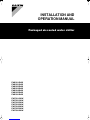 1
1
-
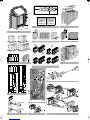 2
2
-
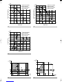 3
3
-
 4
4
-
 5
5
-
 6
6
-
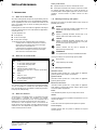 7
7
-
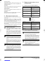 8
8
-
 9
9
-
 10
10
-
 11
11
-
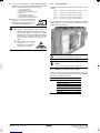 12
12
-
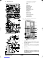 13
13
-
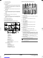 14
14
-
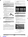 15
15
-
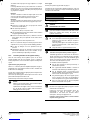 16
16
-
 17
17
-
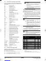 18
18
-
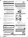 19
19
-
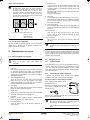 20
20
-
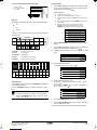 21
21
-
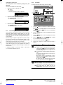 22
22
-
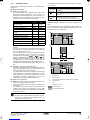 23
23
-
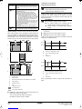 24
24
-
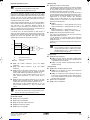 25
25
-
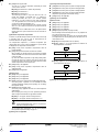 26
26
-
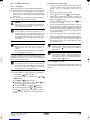 27
27
-
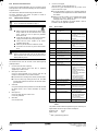 28
28
-
 29
29
-
 30
30
-
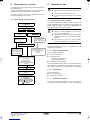 31
31
-
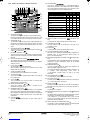 32
32
-
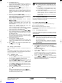 33
33
-
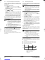 34
34
-
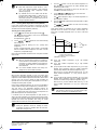 35
35
-
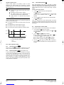 36
36
-
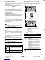 37
37
-
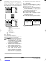 38
38
-
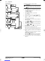 39
39
-
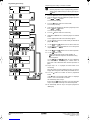 40
40
-
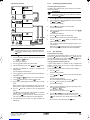 41
41
-
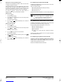 42
42
-
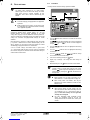 43
43
-
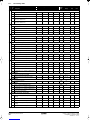 44
44
-
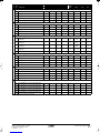 45
45
-
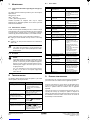 46
46
-
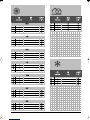 47
47
-
 48
48


Daikin EWAQ050BAW Istruzioni per l'uso
- Categoria
- Condizionatori d'aria a sistema split
- Tipo
- Istruzioni per l'uso
- Questo manuale è adatto anche per


