Moog FusionDome PFDW75T2N Installation And Operation Instructions Manual
- Categoria
- Accessori per telecamere di sicurezza
- Tipo
- Installation And Operation Instructions Manual
Questo manuale è adatto anche per

Moog Inc.
Sensor and Surveillance Systems
3650 Woodhead Drive Northbrook, IL. USA 60062
+1.847.498.0700 Fax: +1.847.498.1258 www.moogS3.com
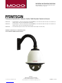
PFDW75C2N
Pressurized FusionDome™ Network Outdoor Wall Mounted Camera Enclosure
PFDW75C2N............. IP Network Ready 7” outdoor pressurized dome housing with WM20G gooseneck wall mount, with 24Vac input, heater and blower, for
Network cameras, 120 to 24Vac, 96vA transformer, clear dome
PFDW75T2N.............. IP Network Ready 7” outdoor pressurized dome housing with WM20G gooseneck wall mount, with 24Vac input, heater and blower, for
Network cameras, 120 to 24Vac, 96vA transformer, tinted dome
PFDW78C2N.............. An extended trim ring model for larger cameras with a maximum camera depthof 243.3mm (9.58”)
Substitute “C” (Clear dome) for “T” (Tinted dome) version
To be used with the 81-IN5481 Instruction Manual.
Installation and Operation Instructions
Before attempting to connect or operate this product, please
read these instructions completely.
© 2013, Moog Inc. All Rights Reserved 81-IN5353 111313

IMPORTANT SAFEGUARDS SAFETY PRECAUTIONS
UNPACKING
SERVICE
1 Read these instructions.
2 Keep these instructions.
3 Heed all warnings
4 Follow all instructions.
5 Do not use this apparatus near water.
6 Clean only with damp cloth.
7 Do not block any of the ventilation openings. Install in accordance with the
manufacturers instructions.
8 Cable Runs- All cable runs must be within permissible distance.
9 Mounting - This unit must be properly and securely mounted to a supporting
structure capable of sustaining the weight of the unit.
Accordingly:
a. This installation should be made by a qualied service person and should conform
to all local codes.
b. Care should be exercised to select suitable hardware to install the unit, taking into
account both the composition of the mounting surface and the weight of the unit.
10 Do not install near any heat sources such as radiators, heat registers, stoves, or other
apparatus ( including ampliers) that produce heat.
11 Do not defeat the safety purpose of the polarized or grounding-type plug. A
polarized plug has two blades with one wider than the other. A grounding type
plug has two blades and a third grounding prong. The wide blade or the third
prong are provided for your safety. When the provided plug does not t into your
outlet, consult an electrician for replacement of the obsolete outlet.
12 Protect the power cord from being walked on or pinched particularly at plugs,
convenience receptacles, and the point where they exit from the apparatus.
13 Only use attachment/ accessories specied by the manufacturer.
14 Use only with a cart, stand, tripod, bracket, or table specied by the manufacturer,
or sold with the apparatus. When a cart is used, use caution when moving the cart/
apparatus combination to avoid injury from tip-over.
15 Unplug this apparatus during lighting storms or when unused for long periods of time.
16 Refer all servicing to qualied service personnel. Servicing is required when the
apparatus has been damaged in any way, such as power-supply cord or plug is
damaged, liquid has been spilled of objects have fallen into the apparatus, the
apparatus has been exposed to rain or moisture, does not operate normally, or
has been dropped.
Be sure to periodically examine the unit and the supporting structure to make sure that the integrity
of the installation is intact. Failure to comply with the foregoing could result in the unit separating
from the support structure and falling, with resultant damages or injury to anyone or anything struck
by the falling unit.
Unpack carefully. Electronic components can be
damaged if improperly handled or dropped. If an item
appears to have been damaged in shipment, replace
it properly in its carton and notify the shipper.
Be sure to save:
1 The shipping carton and packaging material.
They are the safest material in which to make future
shipments of the equipment.
2 These Installation and Operating Instructions.
If technical support or service is needed, contact us at
the following number:
The lightning ash with an arrowhead symbol,
within an equilateral triangle, is intended to
alert the user to the presence of non-insulated
“dangerous voltage” within the product’s
enclosure that may be of sufcient magnitude
to constitute a risk to persons.
Este símbolo se piensa para alertar al usuario a la presencia
del “voltaje peligroso no-aisIado” dentro del recinto de los
productos que puede ser un riesgo de choque eléctrico.
Ce symbole est prévu pour alerter I’utilisateur à la presence
“de la tension dangereuse” non-isolée dans la clôture de
produits qui peut être un risque de choc électrique.
Dieses Symbol soll den Benutzer zum Vorhandensein der
nicht-lsolier “Gefährdungsspannung” innerhalb der
Produkteinschließung alarmieren die eine Gefahr des
elektrischen Schlages sein kann.
Este símbolo é pretendido alertar o usuário à presença “di
tensão perigosa non-isolada” dentro do cerco dos produtos
que pode ser um risco de choque elétrico.
Questo simbolo è inteso per avvertire I’utente alla presenza
“di tensione pericolosa” non-isolata all’interno della
recinzione dei prodotti che può essere un rischio di scossa
elettrica
.
The exclamation point within an equilateral
triangle is intended to alert the user to
presence of important operating and
maintenance (servicing) instructions in the
literature accompanying the appliance.
Este símbolo del punto del exclamation se piensa para
alertar al usuario a la presencia de instrucciones importantes
en la literatura que acompaña la aplicación.
Ce symbole de point d’exclamation est prévu pour alerter
l’utilisateur à la presence des instructions importantes dans
la littérature accompagnant l’appareil.
Dieses Ausruf Punktsymbol soll den Benutzer zum
Vorhandensein de wichtigen Anweisungen in der Literatur
alarmieren, die das Gerät begleitet.
Este símbolo do ponto do exclamation é pretendido alertar o
usuário à presença de instruções importantes na literatura
que acompanha o dispositivo.
Questo simbolo del punto del exclamaton è inteso per
avvertire l’utente alla presenza delle istruzioni importanti nella
letteratura che accompagna l'apparecchio.
TECHNICAL SUPPORT
AVAILABLE 24 HOURS
1- 800-554 -1124
RISK OF ELECTRIC SHOCK
DO NOT OPEN
CAUTION
CAUTION: TO REDUCE THE RISK OF
ELECTRIC SHOCK, DO NOT REMOVE
COVER ( OR BACK). NO USER- SERVICE-
ABLE PARTS INSIDE. REFER SEVICING
TO QUALIFIED SERVICE PERSONNEL.
MADEIN
BUY AMERICA COMPLIANT • COUNTRY OF ORIGIN U.S.A.
USA

Product Warranty Registration
Register Your Products Online
www.moogS3.com/technical-support/product-registration
Moog values your patronage. We are solely committed to providing you with the highest quality products and
superior customer service. With 3-Year and 5-Year warranties (depending on the product purchased) we stand
behind every product we sell.
:
• Simple and Trouble-Free RMA process
• Product / software updates
• Special promotions
• Eliminate the need to archive purchase documents such as receipts, purchase orders, etc.
See full warranty details at www.moogS3.com/technical-support/warranty-plan/

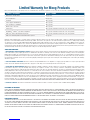
Limited Warranty for Moog Products
Moog - Decatur Operations, subsequently referred to as “Manufacturer,” warrants these products to be free from defects in material or workmanship as follows:
During the labor warranty period, to repair the Product, Purchaser will either return the defective product, freight prepaid, or deliver it to Manufacturer at Moog Decatur
Operations, 2525 Park Central Boulevard, Decatur, Georgia, 30035. The Product to be repaired is to be returned in either its original carton or a similar package affording
an equal degree of protection with a RMA # (Return Materials Authorization number) displayed on the outer box or packing slip. To obtain a RMA# you must contact our
Technical Support Team at 800.554.1124, extension 101. Manufacturer will return the repaired product freight prepaid to Purchaser. Manufacturer is not obligated to
provide Purchaser with a substitute unit during the warranty period or at any time. After the applicable warranty period, Purchaser must pay all labor and/or parts charges.
The limited warranty stated in these product instructions is subject to all of the following terms and conditions.
TERMS AND CONDITIONS
1. NOTIFICATION OF CLAIMS: WARRANTY SERVICE: If Purchaser believes that the Product is defective in material or workmanship, then written notice with an explanation
of the claim shall be given promptly by Purchaser to Manufacturer. All claims for warranty service must be made within the warranty period. If after investigation,
Manufacturer determines the reported problem was not covered by the warranty, Purchaser shall pay Manufacturer for the cost of investigating the problem at its then
prevailing per incident billable rate. No repair or replacement of any Product or part thereof shall extend the warranty period of the entire Product. The specic warranty on
the repaired part only shall be in effect for a period of ninety (90) days following the repair or replacement of that part or the remaining period of the Product parts warranty,
whichever is greater.
2. EXCLUSIVE REMEDY: ACCEPTANCE: Purchaser’s exclusive remedy and Manufacturer’s sole obligation is to supply (or pay for) all labor necessary to repair any Product
found to be defective within the warranty period and to supply, at no extra charge, new or rebuilt replacements for defective parts.
3. EXCEPTIONS TO LIMITED WARRANTY: Manufacturer shall have no liability or obligation to Purchaser with respect to any Product requiring service during the warranty
period which is subjected to any of the following: abuse, improper use, negligence, accident, or acts of God (i.e., hurricanes, earthquakes), modication, failure of the
end-user to follow the directions outlined in the product instructions, failure of the end-user to follow the maintenance procedures recommended by the International Security
Industry Organization, written in product instructions, or recommended in the service manual for the Product. Furthermore, Manufacturer shall have no liability where a
schedule is specied for regular replacement or maintenance or cleaning of certain parts (based on usage) and the end-user has failed to follow such schedule; attempted
repair by non-qualied personnel; operation of the Product outside of the published environmental and electrical parameters, or if such Product’s original identication
(trademark, serial number) markings have been defaced, altered, or removed. Manufacturer excludes from warranty coverage Products sold AS IS and/or WITH ALL FAULTS
and excludes used Products which have not been sold by Manufacturer to the Purchaser. All software and accompanying documentation furnished with, or as part of the
Product is furnished “AS IS” (i.e., without any warranty of any kind), except where expressly provided otherwise in any documentation or license agreement furnished with
the Product. ANY COST ASSOCIATED WITH REMOVAL OF DEFECTIVE PRODUCT AND INSTALLATION OF REPLACEMENT PRODUCT IS NOT INCLUDED IN THIS WARRANTY.
4. PROOF OF PURCHASE: The Purchaser’s dated bill of sale must be retained as evidence of the date of purchase and to establish warranty eligibility.
PRODUCT CATEGORY PARTS \ LABOR
All Enclosures and Electronics Five (5) Years
Accessory Brackets Five (5) Years
Controllers Three (3) Years
Power Supplies / IR Illuminators Three (3) Years
Poles / PolEvators™ / CamEvator Three (3) Years
Warrior Series™ / Q-View™Three (3) Years
SView Series™Three (3) Years 6 months if used in auto scan / tour operation
DeputyDome™, NiteTrac™, Igloo Dome, PurgeDome™Three (3) Years 6 months if used in auto scan / tour operation
EXO Series™ Dome and Fixed Camera Systems* Three (3) Years 6 months if used in auto scan / tour operation
EXO Series™ GeminEye Visible and Thermal Camera Systems One (1) Year
DISCLAIMER OF WARRANTY
EXCEPT FOR THE FOREGOING WARRANTIES, MANUFACTURER HEREBY DISCLAIMS AND EXCLUDES ALL OTHER WARRANTIES, EXPRESS OR IMPLIED, INCLUDING, BUT
NOT LIMITED TO ANY AND/OR ALL IMPLIED WARRANTIES OF MERCHANTABILITY, FITNESS FOR A PARTICULAR PURPOSE AND/OR ANY WARRANTY WITH REGARD TO ANY
CLAIM OF INFRINGEMENT THAT MAY BE PROVIDED IN SECTION 2-312(3) OF THE UNIFORM COMMERCIAL CODE AND/OR IN ANY OTHER COMPARABLE STATE STATUTE.
MANUFACTURER HEREBY DISCLAIMS ANY REPRESENTATIONS OR WARRANTY THAT THE PRODUCT IS COMPATIBLE WITH ANY COMBINATION OF NON-MANUFACTURER
PRODUCTS OR NON-MANUFACTURER RECOMMENDED PRODUCTS PURCHASER MAY CHOOSE TO CONNECT TO THE PRODUCT.
LIMITATION OF LIABILITY
THE LIABILITY OF Manufacturer, IF ANY, AND PURCHASER’S SOLE AND EXCLUSIVE REMEDY FOR DAMAGES FOR ANY CLAIM OF ANY KIND WHATSOEVER, REGARDLESS
OF THE LEGAL THEORY AND WHETHER ARISING IN TORT OR CONTRACT, SHALL NOT BE GREATER THAN THE ACTUAL PURCHASE PRICE OF THE PRODUCT WITH RESPECT
TO WHICH SUCH CLAIM IS MADE. IN NO EVENT SHALL MANUFACTURER BE LIABLE TO PURCHASER FOR ANY SPECIAL, INDIRECT, INCIDENTAL, OR CONSEQUENTIAL
DAMAGES OF ANY KIND INCLUDING, BUT NOT LIMITED TO, COMPENSATION, REPLACEMENT LABOR COSTS, REIMBURSEMENT, OR DAMAGES ON ACCOUNT OF THE LOSS
OF PRESENT OR PROSPECTIVE PROFITS OR FOR ANY OTHER REASON WHATSOEVER.
* NOTE
Moog will repair or replace, at its option, any equipment which is damaged by transient voltage surge/spike or lightning strike (an “Occurrence”), while properly connected
to wired AC power line with protective ground. Any repair or modication of the equipment done by someone other than Moog voids the warranty.
Form 500-911 081913

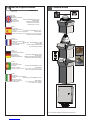
24 VAC
3.3 Amps
Total Power: 80 Watts
Accessories: Heater: 50 Watts/Blower: 2 Watts
Camera Power: 28 Watts Max
Tools Required: .100” Flat Head Screwdriver
Phillips Head Screwdriver
7/16” Wrench or Socket
24 VAC
3.3 amperios
Energía Total: 80 vatios
Accesorios: Calentador: 50 Watts/Blower: 2 vatio
Energía De la Cámara fotográfica: 28 vatios Max
Las Herramientas Requirieron: Destornillador Principal Plano Del 100"
Destornillador Principal Phillips
24 VCA
3.3 ampères
Puissance Totale : 80 watts
Accessoires : Réchauffeur : 50 Watts/Blower : 2 watts
Puissance D'Appareil-photo : 28 watts Max
Les Outils besoin : Tournevis Principal Plat De 100"
Tournevis Principal Phillips
24 VAC
3.3 Ampere
Gesamtenergie: 80 Watt
Zusatzgeräte: Heizung: 50 Watt/Blower: 2 Watt
Kamera-Energie: 28 watts Max
Werkzeuge Erforderten: 100"Flacher Hauptschraubenzieher
Kreuzkopfhauptschraubenzieher
24 VAC
3.3 ampères
Poder Total: 80 watts
Acessórios: Calefator: 50 Watts/Blower: 2 watt
Poder Da Câmera: 28 watts Max
As Ferramentas Requereram: Chave de fenda Principal Lisa Do 100"
Chave de fenda Principal Phillips
24 VAC
3.3 ampère
Alimentazione Totale: 80 watt
Accessori: Riscaldatore: 50 Watts/Blower: 2 watt
Alimentazione Della
Macchina fotografica: 28 watts Max
Attrezzi Richiesti: Cacciavite Capo Piano Del 100"
Cacciavite Capo "phillips"
Electrical Specifications
Power 24VAC
Class 2 Only
!!
PFDW75C2N
Français
Deutsch
Italiano
Portuguese
Español
English
Contents of Box
*** Pan Tilt boxed separately along with its instructions.

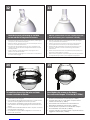
1
Securely mount bracket to wall. Pull wiring
through bracket and position grommet as shown.
• Con seguridad soporte del montaje a emparedar. Tire del cableado
a través del soporte y del ojal de la posición según lo demostrado.
• Solidement parenthèse de bâti à murer. Tirez le câblage par la
parenthèse et le canon isolant de position comme montré.
• Sicher Einfassung Haltewinkel wall. Ziehen Sie Verdrahtung durch
Haltewinkel und Position Gummimuffe, wie gezeigt.
• Firmemente suporte da montagem a wall. Puxe a fiação através do
suporte e do ilhó da posição como mostrado.
• Saldamente staffa del supporto da wall. Tiri i collegamenti tramite la
staffa ed il gommino di protezione di posizione come indicato.
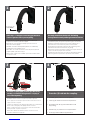
4
Screw the (2) bolts into the coupling.
• Atornille (2) los pernos en el acoplador.
• Vissez (2) les boulons dans l'accouplement.
• Schrauben Sie die (2) Schraubbolzen in die
Koppelung.
• Parafuse (2) os parafusos no acoplamento.
• Avviti (2) i bulloni nell'accoppiamento.
2
Teflon tape™ is wrapped around the pipe threads to
ensure a tight seal and to prevent galling.
• Cinta de Teon ™ se envuelve alrededor de las roscas de la tubería para
asegurar un sello hermético y para evitar el gripado.
• Ruban téon ™ est enroulé autour des letages pour assurer une bonne
étanchéité et éviter tout grippage.
• Teonband ™ ist rund um die Rohrgewinde gewickelt, um eine Abdichtung
zu gewährleisten und zu verhindern Fressen.
• Fita de Teon ™ é enrolado em torno das roscas do tubo para assegurar uma
selagem apertada e para evitar escoriações.
• Teon ™ nastro è avvolto intorno le lettature per assicurare una buona tenuta
e per prevenire l'usura.
•Special anti-seize tape
“DO NOT REMOVE”
3
Screw the coupling tightly onto the pipe threads by
inserting a screwdriver through slots in coupling to
ease in final tightening.
• Atornillar el acoplamiento rmemente en las roscas de las tuberías mediante la inserción de un
destornillador a través de las ranuras de acoplamiento para facilitar el apriete nal.
• Vissez le couplage serré sur le letage de tuyaux en insérant un tournevis dans les fentes de
couplage à l'aise dans le serrage nal.
• Schrauben Sie die Kupplung fest auf die Rohrgewinde durch Einführen eines Schraubendrehers
durch die Schlitze in der Kopplung in dem endgültigen Anziehen zu erleichtern.
• Parafuse o acoplamento bem para as roscas pela inserção de uma chave de fenda através
ranhuras para facilitar o acoplamento no aperto nal.
• Avvitare l'attacco saldamente sulle lettature inserendo un cacciavite nelle fessure di
accoppiamento ad allentarsi nel serraggio nale.
12
34

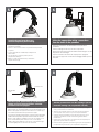
5
Loop the lanyard over the screw
head to temporarily hold housing.
• Loop la cuerda de seguridad en la cabeza del tornillo para mantener
temporalmente la vivienda.
• Enroulez le cordon autour de la tête de vis pour maintenir temporairement
le logement.
• Loop the Lanyard über den Schraubenkopf vorübergehend zu
halten Gehäuse.
• Laço da corda sobre a cabeça do parafuso para reter
temporariamente habitação.
• Avvolgere il cordino sulla testa della vite per memorizzare
temporaneamente alloggi.
6
Make the appropriate wiring connections
from the dome to the pendant.
• Hacer las conexiones de cableado de la cúpula de la
pendiente.
• Faites le câblage de la coupole de la suspension.
• Nehmen Sie die entsprechenden Kabel-Verbindungen von der
Kuppel auf den Anhänger.
• Faça as conexões de cabos da cúpula para o pingente.
• Apportare le opportune connessioni cablaggio dalla cupola a
ciondolo.
7
Undo the lanyard, push housing up and twist. Secure
with the (2) locking bolts and washers. Add third
anti-twist screw if so equipped.
• Deshacer la cuerda de seguridad, empuje y gire hasta la vivienda. Asegure con los
tornillos de bloqueo (2) y las arandelas. Añadir tercero anti-torsión del tornillo si lo tiene.
• Défaire le cordon, appuyer sur le logement et torsion. Fixer avec les vis de blocage (2)
et les rondelles. Ajouter troisième anticorps anti-torsion vis si équipé.
• Lösen Sie die Leine, drücken Gehäuse und Touch. Sichern Sie mit den (2) Verriegelung
Schrauben und Unterlegscheiben. Fügen dritten anti-twist Schraube falls vorhanden.
• Desfazer o cordão, empurrar-se de habitação e torcer. Fixe com os parafusos (2) de
xação e arruelas. Adicionar parafuso anti-torção terceiro se assim equipado.
• Annulla il cordino, spingere abitazioni e torsione. Fissare con le (2) viti di bloccaggio
e le rondelle. Aggiungere un terzo anti-torsione vite se in dotazione.
•Third Anti-Twist
Screw
•Locking Screws
8
Slide the grommet down over the coupling to prevent
water from entering and complete the assembly.
• Resbale el ojal abajo sobre el acoplador para evitar que el agua
entre y para terminar a la asamblea.
• Glissez le canon isolant vers le bas au-dessus de l'accouplement
pour empêcher l'eau d'entrer et pour accomplir l'assemblée.
• Schieben Sie die Gummimuffe unten über der Koppelung, um zu
verhindern, daß Wasser und die Versammlung durchzuführen
hereinkommt.
• Deslize o ilhó para baixo sobre o acoplamento para impedir que a
água entre e para terminar o conjunto.
• Faccia scorrere il gommino di protezione giù sopra l'accoppiamento
per impedire l'acqua entrare e per completare il complessivo.
56
78

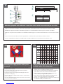
RJ45
24VAC
1
2
3
4
Camera
Camera
Heater/Blower
Heater/Blower
Yellow
Green
Yellow
Green
POWER
Max 80 Watts
26 Watts
1/0
1
2
3
4
Alarm 1
Alarm 2
Alarm 3
Common
Blue
Violet
Gray
White
Make the appropriate male and female connections. Indoor model does not include pre-run cables.
• Haga las conexiones masculinas y femeninas apropiadas. El modelo de interior no incluye pre-funciona los cables.
• Établissez les rapports masculins et femelles appropriés. Le modèle d'intérieur n'inclut pas pré-courent des câbles.
• Stellen Sie die passenden männlichen und weiblichen Beziehungen her. Innenmodell schließt nicht vor-laufen lassen Kabel
ein.
• Faça as conexões masculinas e fêmeas apropriadas. O modelo indoor não inclui pre-funciona cabos.
• Faccia i collegamenti maschii e femminili adatti. Il modello dell'interno non include pre-fa funzionare i cavi.
On board power supply provides 12VDC power
for camera
• A bordo fuente de alimentación proporciona la energía
12VDC para la cámara
• À bord de l'alimentation d'énergie fournit la puissance
12VDC pour l'appareil-photo
• An Bord des Spg.Versorgungsteils stellt Energie 12VDC für
Kamera zur Verfügung
• A bordo da fonte de alimentação fornece o poder 12VDC
para a câmera
• A bordo dell'alimentazione elettrica fornisce il potere 12VDC
per la macchina fotografica
Wire Gauge
Total vA
consumed
,5
22 ,75
20 1,0
18 1,5
16 2,5
14 4
12 6
10 MM2
AWG
5.5 ft
m
400
121
600
182
960
292 ---
10 120
36.5
180
54.9
300
91.4
480
146
800
243
1300
396 -
20 86
27.1
141
43.0
225
68.6
358
109
571
174
905
275
1440
438
30 65
19.8
90
27.4
130
39.6
225
68.6
350
106
525
160
830
252
40 44
13.4
70
21.3
112
34.1
179
54.6
285
86.9
452
138
720
219
50 35
10.6
56
17.1
90
27.4
143
43.6
228
69.5
362
110
576
175
60 29
9.4
47
14.3
75
22.9
119
36.2
190
57.9
301
91.7
480
146
70 25
8.8
40
12.2
64
19.5
102
31.1
163
49.7
258
78.6
411
125
80 31
7.6
34
10.3
55
16.8
85
25.9
140
42.7
215
65.5
340
103
These are recommended maximum distances
for 24VAC with a 10% voltage drop.
• Éstos se recomiendan las distancias máximas para
24VAC con una caída de voltaje del 10%.
• Ceux-ci sont recommandés des distances maximum
pour 24VAC avec une chute de tension de 10%.
• Diese werden maximale Abstände für 24VAC mit
einem 10% Spannungsabfall empfohlen.
• Estes são recomendados distâncias máximas para
24VAC com uma queda de tensão de 10%.
• Questi sono suggeriti distanze massime per 24VAC con
una differenza de potenziale di 10%.
10
9
11

Hand tighten the screws on the dome.
Recommended torque 12 inches/lb (1.35Nm).
• La mano aprieta los tornillos en la bóveda. Esfuerzo de
torsión recomendado 12 inches/lb (el 1.35Nm).
• La main serrent les vis sur le dôme. Couple recom-
mandé 12 inches/lb (1.35Nm).
• Hand ziehen die Schrauben an der Haube fest.
Empfohlene Drehkraft 12 inches/lb (1.35Nm).
• A mão aperta os parafusos na abóbada. Torque
recomendado 12 inches/lb (1.35Nm).
• La mano stringe le viti sulla cupola. Coppia di torsione
suggerita 12 inches/lb (1.35Nm).
To install the dome align the tabs and twist
counter clockwise to secure.
• Para instalar la bóveda alinee las lengüetas y tuerza al revés
a la derecha para asegurar.
• Pour installer le dôme alignez les étiquettes et tordez contre
dans le sens des aiguilles d'une montre pour fixer.
• Um die Haube anzubringen richten Sie die Vorsprünge aus
und verdrehen Sie sich entgegengesetzt nach rechts um zu
sichern.
• Para instalar a abóbada alinhe as abas e torça-as contra no
sentido horário para fixar-se.
• Per installare la cupola allinei le linguette e torca contro in
senso orario per fissare.
Undo the lanyard, pull housing up and twist
secure with the locking bolt and washers.
• Deshaga el acollador, tire de contener para arriba y tuerza seguro
con el perno y las arandelas de fijación.
• Défaites la lanière, tirez loger vers le haut et tordez bloqué avec le
boulon et les rondelles de fermeture.
• Annulieren Sie die Abzuglinie, ziehen Sie oben unterbringen und
verdrehen Sie sicheres mit dem verriegelnschraubbolzen und den
Unterlegscheiben.
• Undo o colhedor, puxe abrigar acima e torça seguro com o
parafuso e as arruelas travando.
• Undo la cordicella, tiri l'alloggio in su e torca sicuro con il bullone e
le rondelle di bloccaggio.
Slide the grommet down over the coupling to prevent
water from entering and complete the assembly.
• Resbale el ojal abajo sobre el acoplador para evitar que el agua
entre y para terminar a la asamblea.
• Glissez le canon isolant vers le bas au-dessus de l'accouplement
pour empêcher l'eau d'entrer et pour accomplir l'assemblée.
• Schieben Sie die Gummimuffe unten über der Koppelung, um zu
verhindern, daß Wasser und die Versammlung durchzuführen
hereinkommt.
• Deslize o ilhó para baixo sobre o acoplamento para impedir que a
água entre e para terminar o conjunto.
• Faccia scorrere il gommino di protezione giù sopra l'accoppiamento
per impedire l'acqua entrare e per completare il complessivo.
1514
1312

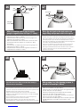
When pressurizing unit be sure to set the
guage or regulator from 10-20psi (.7-1.4bar).
• Al presurizar la unidad sea seguro fijar la medida o el
regulador de 10-20psi (7-1.4bar).
• En pressurisant l'unité soyez sûr de placer la jauge ou le
régulateur de 10-20psi (7-1.4bar).
• Wenn Sie Maßeinheit unter Druck setzen, seien Sie sicher,
das Eichmaß oder den Regler von 10-20psi (7-1.4bar)
einzustellen.
• Ao pressurizar a unidade seja certo ajustar o guage ou o
regulador de 10-20psi (7-1.4bar).
• Nel pressurizzare l'unità sia sicuro regolare il misuratore o
il regolatore da 10-20psi (7-1.4bar).
PSI
0
50
100
150
200
250
300
Nitrogen
Tank
Hose
Regulator
Air Chuck
580
Fitting
Place the air chuck on the tank valve and
begin filling until pressure relief valve opens.
• Coloque la tirada del aire en la válvula del tanque y comience
a llenar hasta que la válvula de descarga de presión se abre.
• Placez le mandrin d'air sur la valve de réservoir et commencez
à remplir jusqu'à ce que la valve de décompression s'ouvre.
• Setzen Sie die Luftklemme auf das Behälterventil und fangen Sie
an zu füllen, bis Druckablaßventil sich öffnet.
• Coloque o mandril do ar na válvula do tanque e comece a
encher-se até que a válvula de escape de pressão abra.
• Disponga il mandrino dell'aria sulla valvola del carro armato e
cominci a riempirsi fino a che la valvola limitatrice della
pressione non si apra.
Air Chuck
Tank
Valve
Open the relief valve. Drain all air from the housing 3
times to remove all moisture.
• Abra la válvula de descarga. Drene todo el aire de la cubierta y
de la repetición 3 times dos veces para quitar toda la humedad.
• Ouvrez la soupape de sécurité. Évacuez tout l'air le logement et la
répétition 3 times pour enlever toute l'humidité.
• Öffnen Sie das Sicherheitsventil. Lassen Sie alle Luft aus dem
Gehäuse und der Wiederholung zweimal ab, um alle Feuchtigkeit
zu entfernen 3 times.
• Abra a válvula de escape. Drene todo o ar da carcaça e do
repeat 3 times para remover toda a umidade.
• Apra la valvola di sfiato. Vuoti due volte tutta l'aria 3 times
dall'alloggiamento e dalla ripetizione per rimuovere tutta l'umidità.
After purging check the housing pressure. It
should be around 5psi (.34bar).
• Después de purgar el cheque la presión de la cubierta.
Debe estar alrededor de 5psi (34bar).
• Après la purge du contrôle la pression de logement. Elle
devrait être autour de 5psi (34bar).
• Nachdem Überprüfung der Gehäusedruck bereinigt
worden ist. Sie sollte um 5psi (34bar) sein.
• Após ter removido a verificação a pressão da carcaça.
Deve ser em torno de 5psi (34bar).
• Dopo l'eliminazione dell'inceppo del controllo la pressione
dell'alloggiamento. Dovrebbe essere intorno a 5psi
(34bar).
PSI
0
5
10
15
20
25
30
17
16
18 19

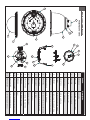
PRESSURIZED HOUSING
Replacement Parts List
4
3
2
1
1
5
6
7
12
11
8
10
9
16
14
15
17
13
16
14
15
17 13
Part No. Description
1 RPPFD040 Housing Top
2 RPVL1938 Removable Pendent Coupling
3 RPVL1802 Plastic Rain Shroud
4 RPVL1795 Tank Valve Gasket
5 RP96RSORG11 Main O-Ring 9.25"
6 RPPFDTR01 Trim Ring w/o Dome
7 RCPFD7 Clear Dome with sealing O-Ring
7b RCTPFD7 Tinted Dome with sealing O-Ring
8 RPPFDT03 Internal Sealing Bracket Assembly
9 RP96RSORG10 Small O-Ring 4.5"
10 RP70PT07a Hermetic Connector, Gasket, Cable
11 RP95VALV08 5 to 7 psi Pressure Relief Valve
12 RP95VALV07 Tank Valve
13 RPFD072 24VAC Heater
14 RPVL1798a ½" Spacers (Set of 4)
15 RP40PCPPFD8 Connection PCB Assembly
16 RPFD060 Main Bracket Assembly
17 RPFD080 Blower
N/S RP40CAPPFD811 External Input Video/Power Cables
N/S RP46PKH2098 Packet Assembly-Hardware
N/S RP46PKH1100 Packet Assembly-Electrical
-
 1
1
-
 2
2
-
 3
3
-
 4
4
-
 5
5
-
 6
6
-
 7
7
-
 8
8
-
 9
9
-
 10
10
-
 11
11


Moog FusionDome PFDW75T2N Installation And Operation Instructions Manual
- Categoria
- Accessori per telecamere di sicurezza
- Tipo
- Installation And Operation Instructions Manual
- Questo manuale è adatto anche per
in altre lingue
- English: Moog FusionDome PFDW75T2N
- français: Moog FusionDome PFDW75T2N
- español: Moog FusionDome PFDW75T2N
- português: Moog FusionDome PFDW75T2N
Documenti correlati
Altri documenti
-
Moog Videolarm FusionDome PFDW75T2N Installation And Operation Instructions Manual
-
-
Moog Videolarm PFD7CN-3 Manuale utente
-
-
Sony UNIOPL7T2 Istruzioni per l'uso
-
Moog Videolarm IRHW75CF2N Installation And Operation Instructions Manual