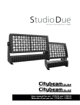
ProLights PIXIEZOOM Manuale utente
- Categoria
- Stroboscopi
- Tipo
- Manuale utente

PIXIEZOOM
PARLED ZOOM
EN - IT
USER MANUAL
MANUALE UTENTE

All rights reserved by Music & Lights S.r.l. No part of this instruction manual may be
reproduced in any form or by any means for any commercial use.
In order to improve the quality of products, Music&Lights S.r.l. reserves the right to modify the
characteristics stated in this instruction manual at any time and without prior notice.
All revisions and updates are available in the ‘manuals’ section on site www.musiclights.it
REV. 03-12/18

1
PIXIEZOOM
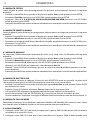
Packing content
• PIXIEZOOM
• Mount bracket
• Power cable
• User manual
TABLE OF CONTENTS
Safety
General instructions
Warnings and installation precautions
1 Introduction
1. 1 Description
1. 2 Technical specications
1. 3 Operating elements and connections
2 Installation
2. 1 Mounting
3 Functions and settings
3. 1 Operation
3. 2 Basic
3. 3 Menu structure
3. 4 Auto show
3. 5 Static mode
3. 6 White presets mode
3. 7 Manual mode
3. 8 Master/Slave mode
3. 9 Full On Mode
3. 10 Linking
3. 11 DMX mode
3. 12 DMX addressing
3. 13 Connection of the DMX line
3. 14 Construction of the DMX termination
3. 15 DMX control
3. 16 Dimmer
3. 17 Back light
3. 18 Fixture information
3. 19 LED frequency
3. 20 Temperature
3. 21 Fan mode
3. 22 White balance
3. 23 KeyLock
3. 24 RDM
4 Maintenance
4. 1 Maintenance and cleaning the unit
4. 2 Trouble shooting
2
2
3
3
5
6
7
7
8
9
10
10
10
10
10
10
11
11
12
12
13
14
14
14
14
14
15
15
15
15
16
16

PIXIEZOOM
2
SAFETY
General instruction
• The products referred to in this manual conform to the European Community Directives and are there-
fore marked with .
• The unit is supplied with hazardous network voltage (230V~). Leave servicing to skilled personnel only.
Never make any modications on the unit not described in this instruction manual, otherwise you will
risk an electric shock.
• Connection must be made to a power supply system tted with ecient earthing (Class I appliance ac-
cording to standard EN 60598-1). It is, moreover, recommended to protect the supply lines of the units
from indirect contact and/or shorting to earth by using appropriately sized residual current devices.
• The connection to the main network of electric distribution must be carried out by a qualied electrical
installer. Check that the main frequency and voltage correspond to those for which the unit is designed
as given on the electrical data label.
• This unit is not for home use, only professional applications.
• Never use the xture under the following conditions:
- in places subject to vibrations or bumps;
- in places with a temperature of over 40 °C.
• Make certain that no inammable liquids, water or metal objects enter the xture.
• Do not dismantle or modify the xture.
• All work must always be carried out by qualied technical personnel. Contact the nearest sales point for
an inspection or contact the manufacturer directly.
• If the unit is to be put out of operation denitively, take it to a local recycling
plant for a disposal which is not harmful to the environment.
Warnings and installation precautions
• If this device will be operated in any way dierent to the one described in this manual, it may suer
damage and the guarantee becomes void. Furthermore, any other operation may lead to dangers like
short circuit, burns, electric shock, etc.
• Before starting any maintenance work or cleaning the projector, cut o power from the main supply.
• Always additionally secure the projector with the safety rope. When carrying out any work, always com-
ply scrupulously with all the regulations (particularly regarding safety) currently in force in the country
in which the xture’s being used.
• Install the xture in a well ventilated place.
• Keep any inammable material at a safe distance from the xture.
• Shields, lenses or ultraviolet screens shall be changed if they have become damaged to such an extent
that their eectiveness is impaired.
• The lamp (LED) shall be changed if it has become damaged or thermally deformed.
• Never look directly at the light beam. Please note that fast changes in lighting, e. g. ashing light, may
trigger epileptic seizures in photosensitive persons or persons with epilepsy.
• Do not touch the product’s housing when operating because it may be very hot.
WARNING! Before carrying out any operations with the unit, carefully read this instruction
manual and keep it with cure for future reference. It contains important information about
the installation, usage and maintenance of the unit.

3
PIXIEZOOM
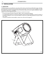
- 1 - INTRODUCTION
PIXIEZOOM is a single-source LED PAR featuring a 6°- 23° linear zoom and a fully homogenised output. Its
IP54 housing and solid build allow it to be used in any event from theaters to festivals.
FEATURES:
• Single 60W RGBW LED source delivers an even beam and full colour spectrum
• Wide linear zoom from 6° to 23°
• IP65 rating allowing for exible use
1.2 TECHNICAL SPECIFICATIONS
LIGHT SOURCE
• Source: 60W RGBW Osram LED
• Luminous ux: 1001lm
• Lux: (6°) 7650 (23°) 590lux @3m full
• Lux: (6°) 2761 (23°) 212lux @5m full
• Source life expectancy: >50.000 h
OPTICS
• Zoom: 6-23° motorised linear zoom
• Lens diameter: 100mm
• Lens type: high-quality glass lens optics
COLOUR SYSTEM
• Colour mixing: RGBW/FC
• CTC: CTC control through independent DMX channel
• White presets: 2000~8000K
• Colour wheel: virtual colour wheel with presets
DYNAMIC EFFECTS
• Static colour mode: selection of static colour
• Manual colour mode: manual adjustment of colour
• Auto mode: built-in programs with execution speed adjustment
BODY
• Body: sturdy die-cast aluminium body conceived for long-time durability
• Body colour: black
CONTROL
• Protocols: DMX512, RDM
• DMX channels: 5 / 7 / 11channel
• RDM: RDM ready for xture remote monitor and settings
• Display: black OLED touch display
• Firmware upgrade: yes, via USB-DMX interface (UPBOX1) not included
• Master/Slave: for synchronized operation of more units linked in a chain
ELECTRONICS
• Dimmer: linear 0~100% electronic dimmer
• Dimmer curves: 4 dierent dimming curves available

PIXIEZOOM
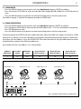
4
182
259 400
Illuminance at a Distance
6°
- 23°
1.0m
3.0m
5.0m
7.0m
10.0m
0m
0.17/1.15m
0.34/2.30m
0.52/3.46m
0.69/4.61m
Lux Center Beam Angle: 6°-
23°
Beam Width
68850/5310lx
7650/ 590lx
2761,7/212,4
lx
0.87/5.77m
1406,2/108,4
lx
688,5/
53,1
lx
Fig.1
Technical drawing
Photometric data
• Strobe / shutter: 1-30 Hz, electronic
• Battery backup: battery backup for user operation without connecting to the main power
• Operating temperature: -20° ~ +45°
• Flicker: icker free frequency with adjustable PWM
• Selectable PWM: 600~25K Hz
ELECTRICAL
• Power supply: 100-240V – 50/60Hz
• Power consumption (at 230V): 89W
• Power consumption (at 120V): 91W
• Output (at 230V): 22 units on a single power line
• Output (at 120V): 12
PHYSICAL
• Cooling: pressure and temperature balance through GORE membrane vents
• Sospension and xing: double hanging bracket suitable for safe hanging and for oor positioning
• Signal connection: Seetronic XLR 5p IN/OUT connectors
• Power connection: Seetronic powerKon waterproof IN/OUT connectors
• IP rating: 54 for outdoor installations
• Dimensions (WxHxD): 259x182x400mm
• Weight: 5.5kg

5
PIXIEZOOM
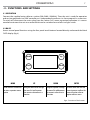
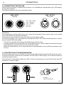
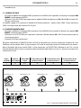
1.3 OPERATING ELEMENTS AND CONNECTIONS
1. SCREW for the mounting bracket
2. MOUNTING BRACKET
3. DMX IN (5-pole XLR):
1 = ground, 2 = DMX -, 3 = DMX +
4. CONTROL PANEL with display and 4 buttons
used to access the control panel functions
and manage them
5. DMX OUT (5-pole XLR):
1 = ground, 2 = DMX-, 3 = DMX+, 4 N/C, 5 N/C
Rear panel Fig.2
6. POWER IN (PowerCON TRUE IN): for
connection to a socket (100-240V~/50-60Hz)
via the supplied mains cable
7. GORE: GORE membrane vents for pressure
and temperature balance
8. POWER OUT: connect to supply power to the
next unit
9. SAFETY RING to attach safety cable
6
5
3
4
79 8
1
2

PIXIEZOOM
6
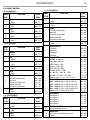
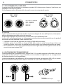
- 2 - INSTALLATION
2.1 MOUNTING
PIXIEZOOM may be set up on a solid and even surface. The unit can also be mounted upside down to a
cross arm. For xing, stable mounting clips are required. The mounting place must be of sucient stability
and be able to support a weight of 10 times of the unit’s weight.
When carrying out any installation, always comply scrupulously with all the regulations (particularly re-
garding safety) currently in force in the country in which the xture’s being used.
• Install the projector at a suitable location by means of the mounting bracket (1).
• Always additionally secure the projector with the safety rope from falling down. For this purpose, fas-
ten the safety rope at a suitable position so that the maximum fall of the projector will be 20 cm.
• Adjust the projector and use the screw to slightly release or tighten the locking mechanism of the
bracket if is necessary (2).
Fig.3
1
2

7
PIXIEZOOM
- 3 - FUNCTIONS AND SETTINGS
3.1 OPERATION
Connect the supplied main cable to a socket (100-240V~/50-60Hz). Then the unit is ready for operation
and can be operated via a DMX controller or it independently performs its show program in succession.
To switch o, disconnect the mains plug from the socket. For a more convenient operation it is recom-
mended to connect the unit to a socket which can be switched on and o via a light switch.
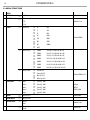
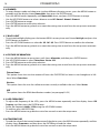
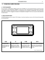
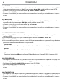
3.2 BASIC
Access control panel functions using the four panel touch buttons located directly underneath the black
OLED display (g.4).
Fig.4 - Functions of the buttons
MENU UP DOWN ENTER
Used to access the menu or
to return a previous menu
option
Navigates downwards through
the menu list and increases
the numeric value when in a
function
Navigates upwards through
the menu list and decreases
the numeric value when in
a function
Used to select and store the
current menu or conrm the
current function value or
option within a menu
Mode
Enter
Up
Down

PIXIEZOOM
8
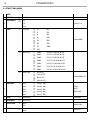
3.3 MENU STRUCTURE
MENU
1
DMX Address
ð
1 - 512 Default: 001
2
DMX Channel
ð
5 Ch
Default: 11 ch7 Ch
11 Ch
3
Static
ð
Fixed Color
ð
R RW
Default: RGBW
ð
G GW
ð
B BW
ð
W RGW
ð
GB RBW
ð
RB GBW
ð
RG RGBW
ð
RGB
ð
White Presets
ð
2000 K R=250, G=180, B=0, W=50
ð
3000 K R=255, G=220, B=0, W=130
ð
4000 K R=235, G=210, B=0, W=255
ð
5000 K R=215 G=210, B=60, W=255
ð
6000 K R=195, G=210, B=80, W=255
ð
7000 K R=185 G=210, B=90, W=255
ð
8000 K R=170, G=210, B=105, W=255
ð
Manual Color
ð
Red (0-255)
Default: RGBW=255
ð
Green (0-255)
ð
Blue (0-255)
ð
White (0-255)
4
Auto Show
ð
Auto 1
ð
Speed (1-100)
Default:
AUTO1
SPEED=100
Auto 2
ð
Speed (1-100)
Auto 3
ð
Speed (1-100)
Auto 4
ð
Speed (1-100)
Auto 5
ð
Speed (1-100)
5
Zoom
ð
Zoom (0-255) Default: 000
6
Zoom Oset
ð
Oset (0-255)
7
Master/Slave
ð
Master
Default: Slave
Slave
8 Full On
ð
HB
Studio
Default :HB

9
PIXIEZOOM
3.4 AUTO SHOW
If no DMX control signal is present at the DMX INPUT, the unit independently runs through its show pro-
gramme provided that the blackout mode is switched o:
• Press the MENU button so many times until the display shows Auto Show, then press the ENTER button.
• Press the UP/DOWN button to switch between the show Auto 1 - Auto 5. The unit will operate in show
mode.
• Using the UP/DOWN button to select the desired run speed slow-fast 1-100.
• Press the ENTER button to save the setting.
IMPORTANT: Programs Auto 1 - 5 are fully pre-programmed and will not be altered by changes.
9
Dimmer Mode
ð
O
Default: OFF
Dimmer 1
Dimmer 2
Dimmer 3
10
White Balance
ð
O
ð
Manual Red (125-255)
Default: RGBW = 255
Green (125-255)
Blue (125-255)
White (125-255)
11
LED Frequency
ð
600 Hz
Default: 1200Hz
1200 Hz
2000 Hz
4000 Hz
25 KHz
12
Fan Mode
ð
Auto Speed
Default: Auto Speed
High Speed
Silent
13
Back Light
ð
On
Default: On
10 S
20 S
30 S
13
Key Lock
ð
On
Default: On
O
15
Information
ð
Fixture Hours
ð
9999h
Version
ð
V1.0
UID
ð
15D00207****
16
Reset Factory
ð
NO
YES

PIXIEZOOM
10
3.5 STATIC MODE
This xture has the ability to accept custom static color settings. Access these chases via the control panel
on the back of the xture.
• Press the MENU button so many times until the display shows Static, then press the ENTER button.
• Select Fixed Color through the UP/DOWN buttons, then press ENTER.
• Set the colors R , G , B, W, GB, RB, RG, RGB, RW, GW, BW, RGW, RBW, GBW, RGBW through the UP/DOWN buttons,
then press ENTER.
• Press the MENU button to go back or to meet the waiting time to exit the setup menu.
3.6 WHITE PRESETS MODE
The white presets mode allow you to choose a preprogrammed white color temperature.
• Press the MENU button so many times until the display shows Static, then press the ENTER button.
• Select White Presets through the UP/DOWN buttons, then press ENTER.
• Choose the white color temperature through the UP/DOWN buttons, then press ENTER.
• Press the MENU button to go back or to meet the waiting time to exit the setup menu.
3.7 MANUAL MODE
This mode allows to combine the colors red, green, blue and white (R, G, B, W).
• Press the MENU button so many times until the display shows Static, then press ENTER.
• Select Manual Color through the UP/DOWN buttons, then press ENTER.
• Select the color R, G, B, W through the UP/DOWN buttons, then press ENTER.
• Using UP/DOWN buttons, select the desired color value 000 - 255.
• Press ENTER button to continue to the next color R, G, B,W.
• Continue until the desired mix is obtained.
• Press the button MENU to go back or to meet the waiting time to exit the setup menu.
3.8 MASTER/SLAVE MODE
This mode will allow you to link up the units together without a controller. Choose a unit to function as the
Master. The unit must be the rst unit in line; other units will work as slave.
• Press the MENU button so many times until the display shows Master/Slave, then press ENTER.
• Using UP/DOWN buttons, select the desired mode and then press ENTER.
• Press the button MENU to go back or to meet the waiting time to exit the setup menu
• Use standard DMX cables to daisy chain your units together via the DMX connector on the rear of the
units. For longer cable runs we suggest a terminator at the last xture (see page 13).
• Set on master xture the desired program (see section 3.4).
• Set the slaves to the same DMX modes.
3.9 FULL ON MODE
Select the Full on Mode function to set the HB Mode (High Brightness Mode, with the maxinum value of
the colors) or Studio Mode with a automatic white balance.
3.10 LINKING
1. Connect the DMX OUT of the master unit via 5-pole XLR cable to the DMX IN of the rst slave unit.
2. Connect the DMX OUT of the rst slave unit to the DMX IN of the second slave unit, etc. until all units
are connected in a chain.

11
PIXIEZOOM
. . . . . . . . . . . .
DMX512 Controller
DMX Address: 33 DMX Address: 48DMX Address: 38 DMX Address: 43
Fig.5 - Example 5 DMX channels conguration
Number of
DMX channels
Start address
(example)
DMX Address
occupied
Next possible start
address for unit No. 1
Next possible start
address for unit No. 2
Next possible start
address for unit No. 3
5 33 33-37 38 43 48
3.11 DMX MODE
• Press the MENU button so many times until show Dmx Channel and press ENTER to conrm.
• Press the button UP/DOWN to select the desired DMX mode 5 Ch, 7 Ch o 11 Ch. Press ENTER button to
store.
• Press the MENU button to go back or to meet the waiting time to exit the setup menu.
The tables on page 14 indicate the operating mode and DMX value.
3.12 DMX ADDRESSING
• Press the MENU button so many times until show Dmx Address and press ENTER to conrm.
• Press the button UP/DOWN to select the desired DMX address 001 - 512. Press and hold to scroll quickly.
• Press ENTER button to store.
• Press the MENU button to go back or to meet the waiting time to exit the setup menu.
To able to operate the PIXIEZOOM with a light controller, adjust the DMX start address for the rst a DMX
channel. If e. g. address 33 on the controller is provided for controlling the function of the rst DMX chan-
nel, adjust the start address 33 on the PIXIEZOOM. The other functions of the light eect panel are then
automatically assigned to the following addresses.
An example with the start address 33 is shown below:

PIXIEZOOM
12
Fig.6
Fig.7
3.13 CONNECTION OF THE DMX LINE
DMX connection employs standard XLR connectors. Use shielded pair-twisted cables with 120Ω imped-
ance and low capacity.
The following diagram shows the connection mode:
ATTENTION
The screened parts of the cable (sleeve) must never be connected to the system’s earth, as this would
cause faulty xture and controller operation.
Over long runs can be necessary to insert a DMX level matching amplier.
For those connections the use of balanced microphone cable is not recommended because it cannot
transmit control DMX data reliably.
• Connect the controller DMX input to the DMX output of the rst unit.
• Connect the DMX output to the DMX input of the following unit. Connect again the output to the input
of the following unit until all the units are connected in chain.
• When the signal cable has to run longer distance is recommended to insert a DMX termination on the
last unit.
3.14 CONSTRUCTION OF THE DMX TERMINATION
The termination avoids the risk of DMX 512 signals being reected back along the cable when they reach-
es the end of the line: under certain conditions and with certain cable lengths, this could cause them to
cancel the original signals.
The termination is prepared by soldering a 120Ω 1/4 W resistor between pins 2 and 3 of the 5-pin male XLR
connector, as shown in gure.
DMX - OUTPUT
XLR socket
DMX - INPUT
XLR plug
Pin1 : GND - Shield
Pin2 : - Negative
Pin3 : + Positive
Pin4 : N/C
Pin5 : N/C
Example:
3 pin XLR connector

13
PIXIEZOOM
3.15 DMX CONTROL
5 CHANNELS
MODE
FUNCTION DMX
Value
5 Ch
1
RED
0~100% 000 - 255
2
GREEN
0~100% 000 - 255
3
BLUE
0~100% 000 - 255
4
WHITE
0~100% 000 - 255
5
ZOOM
0~100% 000 - 255
11 CHANNELS
MODE
FUNCTION DMX
Value
11 Ch
1
DIMMER
0~100% 000 - 255
2
RED
0~100% 000 - 255
3
GREEN
0~100% 000 - 255
7 CHANNELS
MODE
FUNCTION DMX
Value
7 Ch
1
DIMMER
0~100% 000 - 255
2
RED
0~100% 000 - 255
3
GREEN
0~100% 000 - 255
4
BLUE
0~100% 000 - 255
5
WHITE
0~100% 000 - 255
6
STROBE
No Function (shutter open)
Slow to fast
No Function (shutter open)
Random slow to fast
No Function (shutter open)
000 - 030
031 - 100
101 -130
131 - 200
201 - 255
7
ZOOM
0~100% 000 - 255
11 CHANNELS
MODE
FUNCTION DMX
Value
11 Ch
4
BLUE
0~100% 000 - 255
5
WHITE
0~100% 000 - 255
6
STROBE
No Function (shutter open)
Slow to fast
No Function (shutter open)
Random slow to fast
No Function (shutter open)
000 - 030
031 -100
101 - 130
131 - 200
201 - 255
7
ZOOM
0~100% 000 - 255
8
COLOR FUNCTION
No Function
Color presets
White presets
Color macro
000 - 010
011 - 085
086 - 170
171 - 255
9
COLOR PRESETS
RGB 100%, 0~100%, 0%
RGB 0~100%, 100%, 0%
RGB 0%, 100%, 0~100%
RGB 0%, 0~100%, 100%
RGB 0~100%, 0%, 100%
RGB 100%, 0%, 0% ~ 100%
RGB 100%, 0% ~ 100%, 0% ~ 100%
RGB 100% ~ 0%, 100% ~ 0%, 100%
RGBW
0%~100%,0%~100%, 100%, 0%~100%
000 - 028
029 - 056
057 - 084
084 - 112
113 - 140
141 - 168
169 - 196
197 - 224
225 - 255
WHITE PRESETS
2000K ~ 3000K (R=250, G=180, B=0, W=50)
3000K ~ 4000K (R=255, G=220, B=0, W=130)
4000K ~ 6000K (R=235, G=210, B=0, W=255)
6000K ~ 8000K (R=195, G=210, B=80, W=255)
8000K (R=170, G=210, B=105, W=255)
000 - 195
196 - 210
211 - 225
226 - 240
241 - 255
COLOR MACRO
Auto Program 1
Auto Program 2
Auto Program 3
Auto Program 4
Auto Program 5
000 - 060
061 - 110
111 - 160
161 - 210
211 - 255
10
COLOR MACRO SPEED
Color macro speed slow to fast 000 - 255
11
DIMMER FADE
Preset dimmer speed from display menu
0~100%
000 - 000
000 - 255

PIXIEZOOM
14
3.16 DIMMER
• To enter dimmer mode and choose to simulate dierent dimming curves, press the MENU button re-
peatedly until the display shows Dimmer Mode, then press the ENTER button.
• Press the MENU button repeatedly until Dimmer Mode shows, and press ENTER button to accept.
• Use the UP/DOWN buttons to select a dimmer curve O - Dimmer1 - Dimmer2 - Dimmer3.
• Press ENTER button to accept.
• Press ENTER button to conrm the selection.
• Press the MENU button to go back or to meet the waiting time to exit from the setup menu automati-
cally.
3.17 BACK LIGHT
• To activate backlight display press the button MENU so many times until shows Back Light, and press the
ENTER button to conrm.
• Press the UP/DOWN buttons to select On - 10S - 20S - 30S. Press ENTER button to conrm the selection.
• Press the MENU button to go back or to meet the waiting time to exit from the setup menu automati-
cally.
3.18 FIXTURE INFORMATION
1. Press the MENU button so many times until shows Information, and then press ENTER button.
2. Use UP/DOWN button to select: Fixture Hours - Version - UID.
3. Press ENTER button to conrm the selection.
4. Press the MENU button to go back or to meet the waiting time to exit from the setup menu automati-
cally.
Fixture Hours
This option shows the user the amount of hours the PIXIEZOOM has been in use throughout its life-
time. Select Fixture Hours.
Version
This option shows the user the software version currently installed in the unit. Select Version.
UID
This option shows the RDM identication number (see paragraph 3.23)
3.19 LED FREQUENCY
• To adjust the frequency of the LEDs, press the MENU button repeatedly until the display shows LED
Frequency, and then press the ENTER button.
• Select the frequency 600 Hz - 25 KHz using the UP/DOWN buttons.
• To conrm, press the ENTER key.
• Press the MENU button to go back or wait a few seconds to exit the setup menu.
3.20 TEMPERATURE
• To read the value of the internal temperature of the device, press the MENU button repeatedly until the
display shows Temperature, and then press the ENTER key to read the value.
• Press the MENU button to go back or wait a few seconds to exit the setup menu.

15
PIXIEZOOM
3.21 FAN MODE
To set the rotation speed of the fans refer to the following guide:
• Press the MENU key repeatedly until the display shows Fan Mode, then press the button ENTER.
• Select by pressing UP/DOWN one of the following options: Auto - High - Silent. It is possible choose the
speed of rotation of the fans from: fast High, automatic Auto and Silent.
• Press the MENU button to go back or wait a few seconds to exit the setup menu.
3.22 WHITE BALANCE
Enter the White balance to adjust the Red, Green, Blue and White parameter to make dierent whites.
• Press the button MENU so many times until shows White Balance, and press the button ENTER to conrm.
• Select the color R, G, B, W through the buttons UP/DOWN, then press the button ENTER.
• Using UP/DOWN button, select the desired color value 125 - 255.
• Press ENTER button to continue to the next color R, G, B, W.
• Continue until the desired mix is obtained.
• Press the MENU button to go back or to meet the waiting time to exit the setup menu.
3.23 KEY LOCK
Enter the Key Lock mode to select whether the access password is on or o.
• Press the button MODE so many times until show Key Lock and press the button ENTER to conrm.
• Use UP/DOWN button to select: ON or OFF.
• Press ENTER button to conrm the selection.
When the xture is set as pass ON, after 30 seconds or turn on the xture next time, the xture will need
an access password to enter the display menu control.
NOTE - The factory access password is UP + DOWN + UP + DOWN (press ENTER to conrm the access).
3.24 RDM - Remote Device Management
With this function you can call up various submenus via RDM.
This device is RDM ready. RDM stands for “Remote Device Management” and makes remote control of
devices connected to the DMX-bus possible. Manual settings like adjusting the DMX starting address are
no longer needed. This is especially useful when the device is installed in a remote area. RDM is integrated
in DMX without inuencing the connections. The RDM-data is transmitted via the standard XLR-poles 1
and 2 – new DMX-cables are not necessary. RDM ready and conventional DMX devices can be operated
in one DMX line. The RDM protocol sends own packages in the DMX512 data feed and does not inuence
conventional devices. If DMX splitters are used and RDM control is to be used, these splitters must sup-
port RDM. The number and type of RDM parameters depend on the RDM controller (not included) is used.

PIXIEZOOM
16
- 4 - MAINTENANCE
4.1 MAINTENANCE AND CLEANING THE UNIT
• Make sure the area below the installation place is free from unwanted persons during setup.
• Switch o the unit, unplug the main cable and wait until the unit has cooled down.
• All screws used for installing the device and any of its parts should be tightly fastened and should not
be corroded.
• Housings, xations and installation spots (ceiling, trusses, suspensions) should be totally free from any
deformation.
• The main cables must be in impeccable condition and should be replaced immediately even when a
small problem is detected.
• It is recommended to clean the front at regular intervals, from impurities caused by dust, smoke, or
other particles to ensure that the light is radiated at maximum brightness. For cleaning, disconnect the
main plug from the socket. Use a soft, clean cloth moistened with a mild detergent. Then carefully wipe
the part dry. For cleaning other housing parts use only a soft, clean cloth. Never use a liquid, it might
penetrate the unit and cause damage to it.
4.2 TROUBLESHOOTING
Problems Possible causes Checks and remedies
Fixture does not light up
• No mains supply
• Dimmer fader set to 0
• All color faders set to 0
• Faulty LED
• Faulty LED board
• Check the power supply voltage
• Increase the value of the dimmer channels
• Increase the value of the color channels
• Replace the LED board
• Replace the LED board
General low light intensity
• Dirty lens assembly • Clean the xture regularly
Fixture does not power up
• No power
• Loose or damaged power cord
• Faulty internal power supply
• Check for power on power outlet
• Check power cord
• Replace internal power supply
Fixture does not respond to DMX
• Wrong DMX addressing
• Damaged DMX cables
• Bouncing signals
• Check control panel and unit addressing
• Check DMX cables
• Install terminator as suggested
Contact an authorized service center in case of technical problems or not reported in the table can not be
resolved by the procedure given in the table.


REV.03-12/18
Music & Lights S.r.l. si riserva ogni diritto di elaborazione in qualsiasi forma delle presenti istruzioni per l’uso.
La riproduzione - anche parziale - per propri scopi commerciali è vietata.
Al ne di migliorare la qualità dei prodotti, la Music&Lights S.r.l. si riserva la facoltà di modicare, in
qualunque momento e senza preavviso, le speciche menzionate nel presente manuale di istruzioni.
Tutte le revisioni e gli aggiornamenti sono disponibili nella sezione 'Manuali' sul sito www.musiclights.it
La pagina sta caricando ...
La pagina sta caricando ...
La pagina sta caricando ...
La pagina sta caricando ...
La pagina sta caricando ...
La pagina sta caricando ...
La pagina sta caricando ...
La pagina sta caricando ...
La pagina sta caricando ...
La pagina sta caricando ...
La pagina sta caricando ...
La pagina sta caricando ...
La pagina sta caricando ...
La pagina sta caricando ...
La pagina sta caricando ...
La pagina sta caricando ...
La pagina sta caricando ...
La pagina sta caricando ...
La pagina sta caricando ...
La pagina sta caricando ...
-
 1
1
-
 2
2
-
 3
3
-
 4
4
-
 5
5
-
 6
6
-
 7
7
-
 8
8
-
 9
9
-
 10
10
-
 11
11
-
 12
12
-
 13
13
-
 14
14
-
 15
15
-
 16
16
-
 17
17
-
 18
18
-
 19
19
-
 20
20
-
 21
21
-
 22
22
-
 23
23
-
 24
24
-
 25
25
-
 26
26
-
 27
27
-
 28
28
-
 29
29
-
 30
30
-
 31
31
-
 32
32
-
 33
33
-
 34
34
-
 35
35
-
 36
36
-
 37
37
-
 38
38
-
 39
39
-
 40
40


ProLights PIXIEZOOM Manuale utente
- Categoria
- Stroboscopi
- Tipo
- Manuale utente
in altre lingue
- English: ProLights PIXIEZOOM User manual
Documenti correlati
-
ProLights PIXIEZOOM Manuale utente
-
-
-
-
-
-
ProLights 150W IP65 rated full colour COB LED Par Manuale utente
-
-
-