
Model DP524
Two-Channel AC-2 / AC-3
Digital Audio Decoder
Users' Manual
MAIN

MAIN

Users' Manual
For
Model DP524
AC-2 / AC-3 Two-Channel
Digital Audio Decoder
Dolby Laboratories Incorporated
U.S.A. 100 Potrero Avenue, San Francisco, CA 94103
Tel: 415-558-0200; Fax: 415-863-1373
U.K. Wootton Bassett, Wiltshire SN4 8QJ
Tel: 01793-842100; Fax: 01793-842101
DISCLAIMER OF WARRANTIES:
Equipment manufactured by Dolby Laboratories is warranted against defects in materials and
workmanship for a period of one year from the date of purchase. All warranties, conditions or other terms implied by statute are excluded to
the fullest extent allowed by law.
LIMITATION OF LIABILITY:
It is understood and agreed that Dolby Laboratories’ liability whether in contract, in tort, under any warranty, in
negligence or otherwise shall not exceed the cost of repair or replacement of the defective components and under no circumstances shall
Dolby Laboratories be liable for incidental, special, direct, indirect or consequential damages (including but not limited to damage to software
or recorded audio or visual material), or loss of use, revenue or profit even if Dolby Laboratories or its agents have been advised, orally or in
writing, of the possibility of such damages.
This unit complies with the EMC requirements of prEN55103-1 and -2 when installed in accordance with this manual in an E2 environment
Dolby and the double-D symbol are registered trademarks of Dolby Laboratories Licensing Corporation.
©1998 Dolby Laboratories Inc.
ISSUE 3
S98/10536/11869
Dolby Part No. 91394
MAIN

MAIN

TABLE OF CONTENTS
SECTION 1 Introduction
1.1 Introduction ...................................................................................................1-1
1.3 Dolby AC-3 and AC-2...................................................................................1-2
1.4 Data Rates, Sample Rates and Channels.......................................................1-3
1.5 Regulatory Notices........................................................................................1-4
SECTION 2 Applications
SECTION 3 Pre-Installation
3.1 Unpacking......................................................................................................3-1
3.2 Inspection ......................................................................................................3-1
3.2.1 Claims for Shipping Damage ......................................................3-1
3.3 Fusing Information........................................................................................3-1
Main Fuse................................................................................................3-1
Internal Fuse............................................................................................3-2
3.4 Configuring Jumper Settings.........................................................................3-2
3.4.1 Jumpers for Encoded Data In & Timing (J103) ............................3-4
Receive Timing / Receive Data Termination..............................3-4
Request to Send / Terminal Ready Enable..................................3-4
3.4.2 Signal Ground-to-Chassis Link...................................................3-4
3.5 Configuring the Rear Panel DIP Switch S101...............................................3-4
3.5.1 Switch nos. 1, 7 & 8 - Test Tone.................................................3-5
3.5.2 Switch nos. 2, 5 & 6 Software Download..................................3-5
3.5.3 Switch no. 3 - Digital Output Format Selection..........................3-6
3.5.4 Switch nos. 4, 5 & 6 - Command/Aux Data................................3-6
SECTION 4 Installation
4.1 Mounting.......................................................................................................4-1
4.2 Audio Connections........................................................................................4-1
4.2.1 S/PDIF Output - J102..................................................................4-1
4.2.2 AES/EBU Output - J101 .............................................................4-1
4.2.3 Analog Outputs - J106/7..............................................................4-1
4.3 Data, Status, and Remote Control Connections ............................................4-2
4.3.1 Encoded Data In & Timing - J103...............................................4-2
4.3.2 RS-232 (J105)..............................................................................4-2
4.3.3 RS-422 (J106)..............................................................................4-3
4.3.4 Parallel Status and Control (J104)...............................................4-3
SECTION 5 Operation
5.1 Front Panel Status Indicators.........................................................................5-1
5.2 Rear Panel Level Controls.............................................................................5-2
5.3 Test Tone Level.............................................................................................5-2
5.4 Software Downloading Procedure.................................................................5-2
MAIN

SECTION 6 Interface Specification and Description
6.1 DP524 Interface Specifications.....................................................................6-1
AES/EBU Digital Audio Output, J101 ...................................................6-1
S/PDIF Digital Audio Output, J102........................................................6-1
Encoded Data In and Timing, J103, 37-pin D-connector:....................... 6-1
Status / Control, J104, 25-pin D-connector:............................................6-2
RS-232 Port, J105 ...................................................................................6-2
Analog Audio Input, J106 & J107 ..........................................................6-2
6.2 RS-449 Interface Description........................................................................6-3
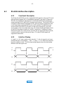
6.2.1 Functional Description...................................................................6-3
6.2.2 Interface Timing.............................................................................6-3
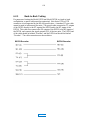
6.2.3 Back-to-Back Testing.....................................................................6-4
6.3 Serial Control ................................................................................................ 6-5
6.3.1 System related commands...........................................................6-5
6.3.2 AC-3 Related commands ............................................................6-7
SECTION 7 Product Specifications
MAIN

SECTION 1
INTRODUCTION
1.1 Introduction
The Dolby Model DP524 is a digital audio decoder unit supporting both Dolby AC-
2 and Dolby AC-3 digital audio coding algorithms. The unit supports up to two
channels of audio. The data rates available are considerably lower than that required
to convey conventional PCM data (between 40k and 384k bits/sec) yet provide
exceedingly high audio quality.
The unit automatically configures itself for the appropriate data rate, sample rate
and algorithm type.
Both digital (AES/EBU and S/PDIF) and analog outputs are provided.
A full duplex serial control system has also been implemented which allows the user
to retrieve Status or Aux. data from the decoder. It is also possible for the user to
update the units software revision by means of a serial download capability.
The decoder provides front panel system status indicators as well as the ability to
respond to serial inquiries relating to system status.
A digitally generated test signal is provided for system alignment and
troubleshooting and can be activated from a rear panel switch or via the serial
control system.
Rear panel analog output level trimmers are provided.
This manual includes installation procedures, descriptions of Model DP524
operation, and interface specifications.
MAIN

1-2
1.2 Features
• Automatic algorithm, data rate and sample rate selection
• Dolby AC-3 audio coding algorithm from 40 kbps - 384 kbps
• Mono, Dual-Mono or Stereo modes for AC-3
• Dolby AC-2 audio coding algorithm from 128 kbps - 384 kbps
• Mono 2-channel modes for AC-2
• Analog outputs with 20-bit D/A converters
• Digital outputs (AES/EBU and S/PDIF)
• Software download capability for software upgrades
• Selectable auxiliary data rates (0 - 9600 baud).
• RS-232 and RS-422 serial interfaces allows Control, Status, Software
Download and Auxiliary data.
• Built-in test tone generator
1.3 Dolby AC-3 and AC-2
Despite the low, spectrum-efficient data rate, Dolby AC-3 and AC-2 yield very high
audio quality and is suitable for the most demanding of professional and consumer
distribution applications. First demonstrated to the film industry in May of 1991,
Dolby AC-3 audio coding technology has evolved into a very sophisticated and
flexible system for the digital representation of high quality sound. Dual channel
implementations of the AC-3 algorithm can be user-configured to operate in Dual
Mono or Stereo modes.
AC-3 and AC-2 are compatible with Dolby Matrix Surround decoding. A wide
range of bit rates and audio coding modes are supported with this audio coding
technique, and are summarized in the tables on the following page.
MAIN

1-3
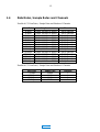
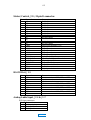
1.4 Data Rates, Sample Rates and Channels
Possible AC-3 Data Rates, Sample Rates and Number of Channels
Data Rate Sample rate Channels
40 kbps 32kHz, 44.1kHz or 48kHz Set by Encoder
48 kbps 32kHz, 44.1kHz or 48kHz Set by Encoder
56 kbps 32kHz, 44.1kHz or 48kHz Set by Encoder
64 kbps 32kHz, 44.1kHz or 48kHz Set by Encoder
80 kbps 32kHz, 44.1kHz or 48kHz Set by Encoder
96 kbps 32kHz, 44.1kHz or 48kHz Set by Encoder
112 kbps 32kHz, 44.1kHz or 48kHz Set by Encoder
128 kbps 32kHz, 44.1kHz or 48kHz Set by Encoder
160 kbps 32kHz, 44.1kHz or 48kHz Set by Encoder
192 kbps 32kHz, 44.1kHz or 48kHz Set by Encoder
224 kbps 32kHz, 44.1kHz or 48kHz Set by Encoder
256 kbps 32kHz, 44.1kHz or 48kHz Set by Encoder
320 kbps 32kHz, 44.1kHz or 48kHz Set by Encoder
384 kbps 32kHz, 44.1kHz or 48kHz Set by Encoder
Possible AC-2 Data Rates, Sample Rates and Number of Channels
Data Rate Sample rate Channels
128 kbps 48kHz 1
192 kbps 48kHz 1
256 kbps 48kHz 2
384 kbps 48kHz 2
MAIN

1-4
1.5 Regulatory Notices
FCC
This equipment has been tested and found to comply with the limits for a Class A
digital device, pursuant to part 15 of the FCC Rules. These limits are designed to
provide reasonable protection against harmful interference when the equipment is
operated in a commercial environment. This equipment generates, uses, and can
radiate radio frequency energy and, if not installed and used in accordance with this
instruction manual, may cause harmful interference to radio communications.
Operation of this equipment in a residential area is likely to cause harmful
interference in which case the user will be required to correct the interference at his
or her own expense.
UL
Troubleshooting must be performed by trained technicians. Do not attempt to
service this equipment unless you are qualified to do so.
WARNING: Check that the correct fuses have been installed. To reduce the risk of
fire, replace the fuses only with the same type and rating.
Exposed portions of the power supply are electrically "hot". In order to reduce the
risk of electrical shock, the power cord MUST be disconnected when the cover of
this equipment is removed.
UK
Connections for the United Kingdom:
WARNING: THIS APPARATUS MUST BE EARTHED
As the colours of the cores in the mains lead may not correspond with the coloured
markings identifying the terminals in your plug, proceed as follows:
• The core which is coloured green and yellow must be connected to the
terminal in the plug which is marked with the letter E or by the earth symbol
or coloured green or green and yellow.
• The core which is coloured blue must be connected to the terminal which is
marked with the letter N or coloured black.
• The core which is coloured brown must be connected to the terminal which is
marked with the letter L or coloured red.
MAIN

1-5
IEC NOTICES
IMPORTANT SAFETY NOTICE
This unit complies with the safety standard IEC65. To ensure safe operation and to guard
against potential shock hazard or risk of fire, the following must be observed:
GB
o Ensure the voltage selector is set to the correct mains voltage for your supply.
o Ensure fuses fitted are the correct rating and type as marked on the unit.
o The unit must be earthed by connecting to a correctly wired and earthed power outlet.
o The power cord supplied with this unit must be wired as follows:
Live—Brown Neutral—Blue Earth—Green/Yellow
IMPORTANT – NOTE DE SECURITE
Ce materiel est conforme à la norme IEC65. Pour vous assurer d'un fonctionnement sans danger et de prévenir
tout choc électrique ou tout risque d'incendie, veillez à observer les recommandations suivantes.
F
o Le selecteur de tension doit être placé sur la valeur correspondante à votre alimentation réseau.
o Les fusibles doivent correspondre à la valeur indiquée sur le materiel.
o Le materiel doit être correctement relié à la terre.
o Le cordon secteur livré avec le materiel doit être cablé de la manière suivante:
Phase—Brun Neutre—Bleu Terre—Vert/Jaune
WICHTIGER SICHERHEITSHINWEIS
Dieses Gerät entspricht der Sicherheitsnorm IEC65. Für das sichere Funktionieren des Gerätes und zur
Unfallverhütung (elektrischer Schlag, Feuer) sind die folgenden Regeln unbedingt einzuhalten:
D
o Der Spannungswähler muß auf Ihre Netzspannung eingestellt sein.
o Die Sicherungen müssen in Type und Stromwert mit den Angaben auf dem Gerät übereinstimmen.
o Die Erdung des Gerätes muß über eine geerdete Steckdose gewährleistet sein.
o Das mitgelieferte Netzkabel muß wie folgt verdrahtet werden:
Phase—braun Nulleiter—blau Erde—grün/gelb
NORME DI SICUREZZA – IMPORTANTE
Questa apparecchiatura è stata costruita in accordo alle norme di sicurezza IEC 65. Per una perfetta
sicurezza ed al fine di evitare eventuali rischi di scossa êlettrica o d'incendio vanno osservate le
I
seguenti misure di sicurezza:
o Assicurarsi che il selettore di cambio tensione sia posizionato sul valore corretto.
o Assicurarsi che la portata ed il tipo di fusibili siano quelli prescritti dalla casa costruttrice.
o L'apparecchiatura deve avere un collegamento di messa a terra ben eseguito; anche la connessione rete deve
avere un collegamento a terra.
o Il cavo di alimentazione a corredo dell'apparecchiatura deve essere collegato come segue:
Filo tensione—Marrone Neutro—Blu Massa—Verde/Giallo
AVISO IMPORTANTE DE SEGURIDAD
Esta unidad cumple con la norma de seguridad IEC65. Para asegurarse un funcionamiento
seguro y prevenir cualquier posible peligro de descarga o riesgo de incendio, se han de observar
E
las siguientes precauciones:
o Asegúrese que el selector de tensión esté ajustado a la tensión correcta para su alimentación.
o Asegúrese que los fusibles colocados son del tipo y valor correctos, tal como se marca en la unidad.
o La unidad debe ser puesta a tierra, conectándola a un conector de red correctamente cableado y puesto a tierra.
o El cable de red suministrado con esta unidad, debe ser cableado como sigue:
Vivo—Marrón Neutro—Azul Tierra—Verde/Amarillo
VIKTIGA SÄKERHETSÅTGÄRDER!
Denna enhet uppfyller säkerhetsstandard IEC65. För att garantera säkerheten och gardera mot
eventuell elchock eller brandrisk, måste följande observeras:
So Kontrollera att spänningsväljaren är inställd på korrekt nätspänning.
o Konrollera att säkringarna är av rätt typ och för rätt strömstyrka så som anvisningarna på enheten föreskriver.
o Enheten måste vara jordad genom anslutning till ett korrekt kopplat och jordat el-uttag.
o El-sladden som medföljer denna enhet måste kopplas enligt foljande:
Fas—Brun Neutral—Blå Jord—Grön/Gul
BELANGRIJK VEILIGHEIDS-VOORSCHRIFT:
Deze unit voldoet aan de IEC65 veiligheids-standaards. Voor een veilig gebruik en om het gevaar van electrische
schokken en het risico van brand te vermijden, dienen de volgende regels in acht te worden genomen:
o Controleer of de spanningscaroussel op het juiste Voltage staat.
NL
o Gebruik alleen zekeringen van de aangegeven typen en waarden.
o Aansluiting van de unit alleen aan een geaarde wandcontactdoos.
o De netkabel die met de unit wordt geleverd, moet als volgt worden aangesloten:
Fase—Bruin Nul—Blauw Aarde—Groen/Geel
MAIN

MAIN

SECTION 2
APPLICATIONS
The Dolby Model DP524 is suitable for a variety of point-to-point and point-to-
multipoint digital transmission applications, including cable, telecommunications
and satellite or terrestrial microwave links. The very high audio quality and low,
spectrum-efficient data rates of the AC-2 and AC-3 coding process make them
particularly appropriate for these applications.
2.1 Cable
Whether for audio-only services or for an enhanced digital audio service
accompanying video, the DP524 is ideally suited to cable applications. The
availability of low data rates permits efficient use of cable bandwidth as either a
baseband signal or as a subcarrier above video.
2.2 Telecommunications
The Model DP524 can be used with T1 or ISDN lines for point-to-point
communications. Film and recording studios, as well as mastering facilities, can be
interconnected with audio and control data to enable multi-site, real-time
operations. Broadcast applications include STL, ICR, and backhaul operations.
Because only a small portion of the T1 bit stream is used, the residual capacity
remains available for additional audio channels or other services (e.g., voice or
computer data), or fractional service can be ordered. In ISDN applications, the
number of "B" channels needed is determined by the chosen bit rate.
MAIN

MAIN

SECTION 3
PRE-INSTALLATION
3.1 Unpacking
Before proceeding further, be sure to inspect the outer carton for shipping damage.
If there has been any penetration to the carton, be sure to inspect the unit for any
physical damage in those areas.
Several accessories have been provided in the packet provided with this manual.
Please compare them with the following list to ensure that there are no missing
items:
Rack screws and washers
Power cord
Spare fuse 1A (Part. No. 56016)
Spare fuse, 2A, used on the internal power supply (Part No. 56017)
Warranty card (Part No. 91292)
Communications Products Group Registration card (Part No. 91228)
3.2 Inspection
Carefully remove the unit from its carton. Remove the plastic wrapping and place
on a flat surface.
If there are no signs of physical damage, proceed to "Fusing Information" below.
3.2.1 Claims for Shipping Damage
If, in your inspection procedure, you should find physical damage, please notify the
carrier immediately. All claims for damage must be filed by the recipient. Dolby
Laboratories or your dealer/distributor will be happy to assist where possible.
3.3 Fusing Information
WARNING To reduce the risk of fire, replace fuses only with the same type and rating.
The DP524 utilizes a universal switching power supply that can accommodate the
full range of nominal voltages between 90 Vac and 264 Vac and any frequency
between 50 Hz and 60 Hz.
Main Fuse
Use 1 Amp, 250V, 20 mm, Time-Lag fuse.
With a small flat-blade screwdriver, open the fuse compartment door in the AC
power input housing (see figure).
MAIN

3-2
OPEN THE
DOOR
ACTIVE
FUSE CARRIER
(LOWER)
FUSE
Check that the fuse in the active (lower) fuse carrier is of the correct rating. A spare
fuse can be stored in the upper fuse carrier position.
Snap the fuse compartment door closed.
Internal Fuse
The switching power supply contains a separate fuse. Most fault conditions should
be protected by the main fuse. The internal fuse rating is:
2 Amp, 250V, 20 mm, fast-blow.
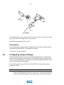
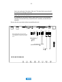
3.4 Configuring Jumper Settings
The Model DP524 includes certain user-selectable options that are configured by
means of internal jumpers, as shown below. Their default settings (shipped with the
unit) are shown in the figure. Any jumpers not specifically mentioned are for factory
use only and should not be disturbed.
If you need to gain access to the interior of the DP524 to change these jumpers,
proceed as follows:
WARNING Be sure that the unit is NOT powered up. The power cord must not be connected.
Using a #2 Phillips head screwdriver, remove the 12 screws securing the top
cover/front panel subassembly to the chassis; there are three screws on the
MAIN

3-3
front, rear, and each of the sides of the unit. The three black screws should
be reserved for affixing at the front.
Note The front panel is attached to the top cover by means of 4 screws also affixing the
handles. These do not need to be removed.
By grasping the front panel handles, gently pull the top cover/front panel
assembly forward then away towards the rear. Carefully set aside this sub-
assembly.
Reverse the above procedure when re-assembling the unit.
S101
J200
DP524 MOTHERBOARD
1
[ON]
OFF
Signal Ground to
Chassis Ground Link
[Open]
Linked
J103
J201
J202
J203
J204
J3
J205
J206
RT RD
J209
J210
J207
J208
TR
RS
[Terminated (150 ohm)]
Not Terminated
J105
Note: Jumpers J200, 201, 202, 203,204
are not applicable to this product and should
not be disturbed. Leave them in the positions
shown.
MAIN

3-4
3.4.1 Jumpers for Encoded Data In & Timing (J103)
Receive Timing J205 / Receive Data J206 [terminated]
Termination resistors (150 ohms) are provided across the "RT" and "RD" inputs.
These inputs are terminated in the default configuration, which should be
appropriate for most applications. Certain situations may require that these inputs
be unterminated (e.g., multiple inputs driven from a single output).
Request to Send J207 & J208 / Terminal Ready J209 & J210 [on]
Handshake signals "RS" and "TR" can be turned on or off, depending on the
application. The default settings for these signals is "on."
3.4.2 Signal Ground-to-Chassis Link J3 [open]
It is normal practice to connect signal ground to power line ground for many
reasons, including safety. In most systems, minimum induced hum is obtained when
this connection is made at one and only one piece of equipment in the audio chain.
To minimize the addition of circulating ground currents in a particular installation,
the default setting is for this jumper link to be open. Note that there is always a 1k
ohm resistor across the link so that the audio ground is never totally isolated from
the chassis ground. To connect audio ground directly to chassis ground in the
DP524, move jumper J3 to the closed position (move jumper towards the front of
the unit).
CAUTION The chassis is always connected to the ground pin of the power line cord. For safety
reasons this ground wire MUST NEVER be disconnected.
3.5 Configuring the Rear Panel DIP Switch S101
The Model DP524 includes certain user-selectable options that are configured by
means of a rear panel DIP switch, S101. Some of them should be configured prior
to first use. Others can be changed as operational needs dictate (See also Section 5,
Operation).
The default settings (delivered from the factory) are shown in brackets in the table
below. Before installing the unit, be sure to verify that the switch positions are in
their desired positions. Explanations follow below.
S101 Switch No. Function Up (On) Down (Off)
1 Test Tone Tone on [Normal]
2 Download/Normal Download [Normal]
3 AES/EBU / S/PDIF [AES/EBU] S/PDIF
4 Command/Aux data mode Command mode [Aux Data mode]
5 Baud rate select 1 See below [See below]
6 Baud rate select 2 See below [See below]
7 Test Tone sample rate 1 See below [See below]
8 Test Tone sample rate 2 See below [See below]
MAIN

3-5
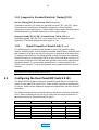
Note Switch positions 5 and 6 take on two roles:
• They set the Aux Data output baud rate when S101-2 is in the Normal position and S101-4 is in the
Aux Data position
• They set the Download baud rate when S101-2 is in the Download position.
• Their positions are immaterial when S101-2 is in the Normal position and S101-4 is in the Command
position; the Command baud rate is at a fixed 9600 baud.
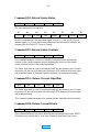
3.5.1 Switch nos. 1, 7 & 8 - Test Tone [down]
Switch position S101-1 activates the built-in test tone generator at a nominal -18dB
amplitude relative to both digital and analog full scale. The decoded signal is
interrupted when the test tone is activated. Switch positions S101-7 and S101-8 are
typically chosen to correspond to the incoming sample rate, so that both the test
tone and audio output have the same sample rate. The frequency of the test tone
varies somewhat with the sample rate chosen.
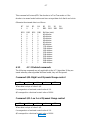
Output Sample
Rate
Frequency S101-7 S101-8
48 kHz 1125 Hz [Down] [Down]
44.1 kHz 1033 Hz Down Up
32 kHz 750 Hz Up Down
Illegal Undefined Up Up
Keep S101-1 in the Normal position when not using this feature.
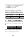
3.5.2 Switch nos. 2, 5 & 6 Software Download [down]
The RS-232 port (J105) can be used for upgrading of the audio coding algorithm
software.
When invoking the download mode, the baud rate selection switches S101-5 and
S101-6 must also be set, depending on the data transfer rate, per the following
table:
Baud Rate S101-5 S101-6
9,600 [Down] [Down]
19,200 Down Up
38,400 Up Down
See Section 5.4 for download instructions. RS-232 interface specifications are
located in Section 6.1.
Keep S101-2 in the Normal position when not using this feature.
MAIN

3-6
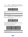
3.5.3 Switch no. 3 - Digital Output Format Selection [up]
Position this switch to corresponds to the type of digital output signal format. Refer
to Section 4 for information regarding audio connections.
Format S101-3
S/PDIF Down
AES/EBU [Up]
The switch setting selects how the digital bit stream is marked. S/PDIF is
synonymous with "consumer" format, AES/EBU is synonymous with "professional"
format.
Note Digital audio output is fed to both the BNC and the XLR connectors of the rear of the unit
simultaneously. However, only one of the connectors may be used at a time; otherwise the unit will be
excessively loaded, and may malfunction.
3.5.4 Switch nos. 4, 5 & 6 - Command/Aux Data [down]
Switch position determines whether the RS-232 port J105 is configured as an Aux
Data output or is used for remote control.
Mode S101-4
Aux Data [Down]
Command Up
In Aux Data mode, the unit will send out serial data contained in the digital audio
data stream at the baud rate defined by the table below.
In Command Mode, the unit responds to a series of five byte packets at a fixed rate
of 9600 baud. See Section 6.3 for further details.
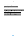
Switch 5 & 6 sets the baud rate for the AC-3 Aux Data channel as follows:
Baud Rate (AC-3) S101-5 S101-6
0 [Down] [Down]
1200 Down Up
2400 Up Down
9600 Up Up
Notes No handshaking is used in Aux Data mode.
AC-2 Mono supports an aux data rate of 600 Baud only; AC-2 Stereo supports 1200 Baud only. The position
of these switches is therefore immaterial.
MAIN
La pagina si sta caricando...
La pagina si sta caricando...
La pagina si sta caricando...
La pagina si sta caricando...
La pagina si sta caricando...
La pagina si sta caricando...
La pagina si sta caricando...
La pagina si sta caricando...
La pagina si sta caricando...
La pagina si sta caricando...
La pagina si sta caricando...
La pagina si sta caricando...
La pagina si sta caricando...
La pagina si sta caricando...
La pagina si sta caricando...
La pagina si sta caricando...
La pagina si sta caricando...
La pagina si sta caricando...
-
 1
1
-
 2
2
-
 3
3
-
 4
4
-
 5
5
-
 6
6
-
 7
7
-
 8
8
-
 9
9
-
 10
10
-
 11
11
-
 12
12
-
 13
13
-
 14
14
-
 15
15
-
 16
16
-
 17
17
-
 18
18
-
 19
19
-
 20
20
-
 21
21
-
 22
22
-
 23
23
-
 24
24
-
 25
25
-
 26
26
-
 27
27
-
 28
28
-
 29
29
-
 30
30
-
 31
31
-
 32
32
-
 33
33
-
 34
34
-
 35
35
-
 36
36
-
 37
37
-
 38
38


Dolby Laboratories Home Security System DP524 Manuale utente
- Tipo
- Manuale utente
- Questo manuale è adatto anche per
in altre lingue
Documenti correlati

Altri documenti
-
 Western Telematic CAS-81 Manuale utente
-
Yamaha CBX-D5 Manuale utente
-
Grace m906 Manuale del proprietario
-
Teleco Televisore TEV22D Manuale utente
-
-
Telos Alliance AERO.2000 Manuale utente
-
Finlux 32FDB5522 Manuale utente
-
-
Telefunken D32H289N4 Manuale utente
-
