DTS Wonder D Manuale utente
- Categoria
- Proiettori
- Tipo
- Manuale utente
Questo manuale è adatto anche per

D.T.S. Illuminazione s.r.l.
Via Fagnano Selve 10/12/14
47843 Misano Adriatico (RN) ITALIA Tel +39 0541 611131 Fax +39 0541 611111 info@dts-lighting.it http://www.dts-lighting.it
Made in Italy
User’s Manual rel 1.0 GB

2
Le informazioni contenute in questo documento sono state attentamente redatte e
controllate. Tuttavia non è assunta alcuna responsabilità per eventuali inesattezze.
Tutti i diritti sono riservati e questo documento non può essere copiato, fotocopiato,
riprodotto per intero o in parte senza previo consenso scritto della D.T.S .
D.T.S. si riserva il diritto di apportare senza preavviso cambiamenti e modifiche
estetiche , funzionali o di design a ciascun proprio prodotto. D.T.S non assume alcuna
responsabilità sull’uso o sull’applicazione dei prodotti o dei circuiti descritti.
The information contained in this publication has been carefully prepared and
checked. However, no responsibility will be taken for any errors. All rights are
reserved and this document cannot be copied, photocopied or reproduced, in part or
completely, without prior written consent from D.T.S.
D.T.S. reserves the right to make any aesthetic, functional or design modifications to
any of its products without prior notice. D.T.S. assumes no responsibility for the use or
application of the products or circuits described herein.
Les informations contenues dans le présent manuel ont été rédigées et contrôlées
avec le plus grand soin. Nous déclinons toutefois toute responsabilité en cas
d'éventuelles inexactitudes. Tous droits réservés. Ce document ne peut être copié,
photocopié ou reproduit, dans sa totalité ou partiellement, sans le consentement
préalable de D.T.S.
D.T.S. se réserve le droit d'apporter toutes modifications et améliorations esthétiques,
fonctionnelles ou de design, sans préavis, à chacun de ses produits. D.T.S. décline
toute responsabilité sur l'utilisation ou sur l'application des produits ou des circuits
décrits.
Las informaciones contenidas en este documento han sido cuidadosamente
redactadas y controladas. Con todo, no se asume ninguna responsabilidad por
eventuales inexactitudes. Todos los derechos han sido reservados y este documento
no puede ser copiado, fotocopiado o reproducido, total o parcialmente, sin previa
autorización escrita de D.T.S.
D.T.S. se reserva el derecho a aportar sin previo aviso cambios y modificaciones de
carácter estético, funcional o de diseño a cada producto suyo. D.T.S. no se asume
responsabilidad de ningún tipo sobre la utilización o sobre la aplicación de los
productos o de los circuitos descritos.

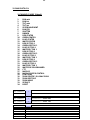
3
INDEX:
1 - SYMBOLS........................................................................................................................... 4
2 - GENERAL WARNING......................................................................................................... 5
3 - GENERAL WARRANTY CONDITIONS .............................................................................. 5
4 - TECHNICAL FEATURES .................................................................................................... 5
5 - ACCESSORIES .................................................................................................................. 7
6 - IMPORTANT SAFETY INFORMATION .............................................................................. 8
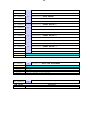
6.1 Fire prevention ............................................................................................................... 8
6.2 Prevention of electric shock ........................................................................................... 8
6.3 Safety ............................................................................................................................ 8
6.4 Level of protection against the penetration of solid and liquid objects ............................ 8
6.5 Long-life auto-charging buffer battery ............................................................................ 8
7 - VOLTAGE AND FREQUENCY ........................................................................................... 9
8 - INSTALLATION .................................................................................................................. 9
8.1 Safety cable ................................................................................................................. 10
8.2 Protection against liquids ............................................................................................. 10
8.3 Movement .................................................................................................................... 11
8.4 Risk of fire .................................................................................................................... 11
8.5 Forced ventilation ........................................................................................................ 11
8.6 Ambient temperature ................................................................................................... 11
9 - MAINS CONNECTION ...................................................................................................... 12
9.1 Protection .................................................................................................................... 12
10 - DMX SIGNAL CONNECTION ......................................................................................... 13
10.1 DMX addresses ....................................................................................................... 13
10.2 Selecting the DMX address ...................................................................................... 13
11 - FIRMWARE UPDATING ................................................................................................ 14
12 - DISPLAY FUNCTIONS .................................................................................................. 15
13 - PERIODIC CLEANING .................................................................................................... 19
13.1 Front lenses screen glass ........................................................................................ 19
13.2 Fans and air passages ............................................................................................. 19
14 - PERIODIC CONTROLS ................................................................................................. 19
15 - DMX PROTOCOL ........................................................................................................... 21

4
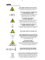
1- SYMBOLS
Graphic symbols used on this manual:
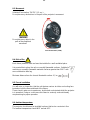
THIS SYMBOL INDICATES A HOT SURFACE
Never handle the unit until at least 10 minutes have
elapsed since the projector was turned off.
THIS SYMBOL INDICATES TEMPERATURE
OF THE EXTERNAL SURFACE
The maximum temperature that can be reached
on the external surface of the fitting, in a
thermally steady state, is 80°C (176°F).
THIS SYMBOL INDICATES THE
ELECTRIC SHOCK RISK
High voltage is present inside the unit. Unplug the
unit prior to performing any function which
involves touching the inside of the moving head.
THIS SYMBOL INDICATES PROTECTION
AGAINST ELECTRICAL SHOCK
Connection must be made to a power supply system
fitted with efficient earthing (Class I appliance).
THIS SYMBOL INDICATES GENERAL RISK
THIS SYMBOL MEANS YOU CAN PLACE THE
UNIT ON NORMALLY FLAMMABLE SURFACES
Suitable for mounting on normally flammable
materials surfaces greater than 200°C with
some combustion time lag.
THIS SYMBOL MEANS
PHOTOBIOLOGICAL SAFETY
Caution: Possibly hazardous optical radiation emitted
from this product. Do not stare at operating light
source. May be harmful to the eyes.
THIS SYMBOL INDICATES THE MINIMUM
DISTANCE FROM ILLUMINATED OBJECTS
LONG-LIFE AUTO-CHARGING BUFFER BATTERY
The projector contains a rechargeable lead-acid or
lithium iron tetraphosphate battery. To preserve the
environment, please dispose the battery at the end
of its life according to the regulation in force.
!

5
2- GENERAL WARNING
Read the instruction contained in this user manual carefully, as they give important
information regarding safety during installation, use and maintenance.
The device is not for domestic use and must be installed by a qualified electrician or
experienced person.
Always disconnect the device from the mains before maintenance.
The device must always be equipped with an efficient ground connection.
3- GENERAL WARRANTY CONDITIONS
The unit is guaranteed for 36 months from the date of purchase against manufacturing
material defects.
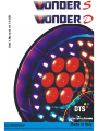
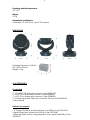
4- TECHNICAL FEATURES
Overview
WONDER S introduces a revolutionary fixture architecture: an exclusive optical
system consisting of two concentric zones, each featuring a different type of lenses.
This new technology achieves an unprecendeted result: the brightest most uniform
wall wash ever seen.
In traditional wash lights, in fact, when the beam is widened to illuminate a larger area,
a darker spot is visible in the center. The exclusive optics of the WONDER S, however
lets you balance the brightness of the entire beam with that of its center, resulting in
unparalleled evenly diffused luminosity.
You can also obtain stunning multicolor projections: WONDER S LED board consists
of four independent zones: a central one, and a ring divided into three distinct
sections. Each of these four areas has individual control of luminosity, colors and
effects: it’s like having four LED fixtures in one.
The unit is also available as WONDER D, offering an exclusive double concentric
optical system featuring different lenses and linear zoom ranges (central: 3.5° - 52°
zoom; ring: 8° - 52° zoom).
This revolutionary configuration results in an unprecendented evenly diffused
luminosity, size and color.
WONDER D can create amazing concentric multi-color beams and effects in the air,
guaranteed to astonish any audience. Also, WONDER D comes equipped with the
‘FPR’ system (D.T.S. patent), which allows limitless pan rotation, in either direction,
never having to reverse motion.
WONDER S FC
(D.T.S. Product Code: 03.LDR014.F)
• Electronic ballast 90-260Vac 50-60 Hz • Black finish
WONDER D FPR FC
(D.T.S. Product Code: 03.LDR013.FFP)
• Electronic ballast 90-260Vac 50-60 Hz • FPR (Free Pan Rotation) • Black finish

6
4- TECHNICAL FEATURES
LED Technology
49 FULL COLOUR LEDs (RGBW)
Optical group
WONDER S:
7 x 3.5° lenses; 42 x 8° lenses
3.5° - 52° long excursion high-efficiency linear motorized zoom
22.000 Lux / 5 m
WONDER D:
2 concentric independent high efficiency optical groups
Optical group 1 (7 lenses): 3.5° - 52° long excursion linear motorized zoom
Optical group 2 (42 lenses): 8°- 52° long excursion linear motorized zoom
22.000 Lux / 5 m
Color generation
4 discrete LED areas; each area is independently controllable (luminosity, colors,
effects) 16 million colors each
Wide palette of pure uniform whites with variable linear color temperature (2700K –
8000K)
Interface / Control / Programming
LCD graphic display + 4 soft-keys (control / management of the main parameters)
Long-life auto-charging buffer battery
RDM
ARTNET ready
Wireless ready
Updatable internal operating system
Li-Fe display backup battery (WONDER D)
DMX channels
34 ch (Default) or 38 ch
Pan & Tilt
WONDER S:
Pan 540°: 2.5 sec.; Tilt 270°: 1.5 sec
WONDER D:
‘FPR’ system (D.T.S. patent)
Pan: limitless rotation, in both directions; 360° rotation in 1.56 sec.; Tilt 270°: 1.5 sec.
Tri-phase stepper motor technology for ultra-fast silent movements
16-bit resolution
Selectable speed ranges
Pan / Tilt lock
Power supply
Electronic full-range 90-260Vac 50-60 Hz
Power consumption: 850W
Connection
DMX: 4 XLR connectors (3-pole In and Out; 5-pole In and Out) by Neutrik
Power supply: POWERCON IN and OUT (re-launch) connectors by Neutrik

7
Operating ambient temperature
-10° / 40°
Weight
22 Kg
International certifications
Certification CE; LED Class: Class 2 LED product
DIMENSIONS
Packaging Dimensions (LxWxH)
610 x 410 x 695 mm
Weight: 27 Kg
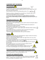
5- ACCESSORIES
As standard
* 1 x POWERCON male cable connector (Code 0520P014)
* 1 x XLR 5 Pins male cable connector (Code 0508B066)
* 1 x XLR 5 Pins female cable connector (Code 0508B065)
* 2 x Omega clamp with “Fast Lock” connection 1/4 turn (Code 02K00549)
* User’s manual
Optional (on request)
• “C” Clamp G100 black / professional (max. load 200Kg) (Code 0521A015)
• Aliscaf Clamp (max. capacity load 100Kg) (Code 0521A008)
• Safety wire (3mm x 60 cm), ring spring catch, max. capacity load 60Kg (Code
0521A010)

8
6- IMPORTANT SAFETY INFORMATION
6.1 Fire prevention:
-It is permissible to place the unit on normally flammable surfaces.
Suitable for mounting on normally flammable materials surfaces greater than 200°C
with some combustion time lag.
-Minimum distance from the closest illuminable surface: 0,5 m.
-Replace any blown or damaged fuses only with those of identical value (10AT).
Refer to the wiring diagram if there is any doubt.
-Connect the projector to mains power via a thermal magnetic circuit breaker.
It is, moreover, recommended to protect the supply lines of the projectors from
indirect contact and/or shorting to earth by using appropriately sized residual current
devices.
6.2 Prevention of electric shock:
-High voltage is present inside the unit.
Unplug the unit prior to performing any function which involves touching the inside of
the moving head.
-The level of technology inherent in the WONDER requires the assistance of
specialised personnel for all servicing.
Please refer to an authorised D.T.S. service centre.
-Connection must be made to a power supply system fitted with efficient earthing
(Class I appliance).
-A good earth connection is essential for proper functioning of the projector.
-Never connect the unit without proper earth connection.
-The fixture should be located in places with a good air ventilation.
6.3 Safety:
-The projector should always be installed with bolts, clamps and other tools that are
capable of supporting the weight of the unit.
-Always use a second safety cable to sustain the weight of the unit in case of the
failure of the main fixing point.
-The maximum temperature that can be reached on the external surface of the fitting,
in a thermally steady state, is 80°C (176°F).
Never handle the unit until at least 10 minutes have elapsed since the projector
was turned off.
-Never install the fixture in an enclosed area lacking sufficient air flow.
The ambient temperature should not exceed 40°C.
-Caution: Possibly hazardous optical radiation emitted from this product.
Do not stare at operating light source. May be harmful to the eyes.
6.4 Level of protection against the penetration of solid and liquid objects:
-The projector is classified as an ordinary appliance and its protection level
against the penetration of solid and liquid objects is IP20.
6.5 Long-life auto-charging buffer battery:
-The projector contains a rechargeable lead-acid or lithium iron tetraphosphate
battery. To preserve the environment, please dispose the battery at the end
of its life according to the regulation in force.
!
!
!

9
7- VOLTAGE AND FREQUENCY
The WONDER with electronic ballast can operate at 90-260Vac 50-60 Hz.
8- INSTALLATION
WONDER may be either floor or ceiling mounted.
For floor mounting installations, the WONDER is
supplied with four rubber mounting feet on the
base. For ceiling mounted installations, we
reccomend the use of appropriate clamps to fix
the unit to the mounting surface.
The supporting structure from which the unit is hung should be capable of bearing the
weight of the unit, as should any clamps used to hang it.
The structure should also be sufficiently rigid so as not to move or shake whilst the
WONDER is moving.
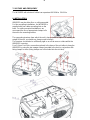
Four 1/4 turn Fast Locks connections placed in the base of the unit allow to hang the
WONDER by using the two omega clamps (provided in the box) in conjunction with
fixing clamps for truss (fixing clamps are not included into the unit box).

10
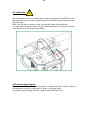
8.1- Safety cable
We recommend the use of a safety cable or chain connected to the WONDER and to
the suspension truss in order to avoid the fixture accidentally falling should the main
fixing point fail.
Make sure that the iron cable or chain can bear the weight of the entire unit.
You may attach the safety chain/cord to the attachment point (A) located on the base
of the fixture, as shown in the picture below.
8.2 Protection against liquids
The projector contains electric and electronic components which should under no
circumstances come into contact with oil, water or any other liquid.
The proper unit functioning would be compromised should this occur.
!

11
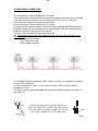
8.3- Movement
Unlimited Pan rotation; Tilt 270° (1,5 sec.) .
Do not place any obstructions in the path of the projector's movement.
WARNING
Do not place any object in the
path of the projector’s
movement
Free Pan Rotation (‘FPR’)
8.4- Risk of fire
Each fixture produces heat and must be installed in a well-ventilated place.
It is permissible to place the unit on normally flammable surfaces. Suitable for
mounting on normally flammable materials surfaces greater than 200°C with
some combustion time lag.
Minimum distance from the closest illuminable surface: 0,5 m.
8.5- Forced ventilation
You will note, on inspection, that the unit features various air inlets and cooling fans
located on both the base and head of the fixture.
These should, under no circumstances, be blocked or obstructed whilst the projector
is in operation. Doing so could cause the fixture to seriously overheat thereby
compromising its proper operation.
8.6- Ambient temperature
The projector should never be installed in places that lack a constant air flow.
The ambient temperature should NOT exceed 40°C.
!
!

12
9- MAINS CONNECTION
WONDER with electronic ballast operates at 90-260V 50-60 Hz.
Prior to connecting the unit to your mains supply, ensure that the model in your
possession correctly matches the mains supply available.
For connection purposes, ensure that your plug is capable of supporting 4 amps
at 230 VOLT, or 10 amps at 90 VOLT each unit connected.
Strict adherence to regulatory norms is strongly recommended.
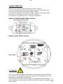
MAINS AC OUTPUT 90-260V 50/60 Hz (16A Max)
Max 4 WONDER Units @ 230V
Max 2 WONDER Units @ 120V
MAINS AC INPUT 90-260V 50/60 Hz
FUSE 10A T
9.1- Protection
The use of a thermal magnetic circuit breaker is recommended for each WONDER.
It is, moreover, recommended to protect the supply lines of the projectors by using
Appropriately sized residual current devices.
Connection must be made to a power supply system fitted with efficient earthing
(Class I appliance). A good earth connection is essential for the correct operation
of the projector.
!

13
10- DMX SIGNAL CONNECTION
The unit operates using the digital DMX 512 signal.
Connection between the mixer and the projector or between projectors must be carried
out using a two pair screened ø 0.5 mm cable and a XLR 5 or 3 pins connector.
Ensure that the conductors do not touch each other.
Do not connect the cable ground to the XLR chassy.
The plug housing must be isolated. Connect the mixer signal to the DMX IN projector
plug and connect it to the next projector by connecting the DMX OUT plug on the first
projector to the DMX IN plug of the second one.
This way, all the projectors are cascade connected.
NB. If the display showing the DMX address flashes, then one of the following errors
has occurred:
- DMX signal not present
- DMX address not valid
- DMX reception problem
For Installations where long distance DMX cable connections are needed, we suggest
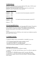
to use a DMX terminator.
The DMX terminator is a male XLR 3-5 pins connector with a 120 ohm resistor
between pin 2 and 3.
The DMX terminator must be plugged into the last unit (DMX out panel connector) of
the DMX line.
PLACE A 120 OHM RESISTOR BETWEEN PIN 2
AND 3 OF A MALE XRL CONNECTOR AND PLUG IT
INTO THE DMX OUT PANEL CONNECTOR OF THE
LAST UNIT CONNECTED TO THE DMX LINE
1
2
3
5
4
OUT
120 ohm
PIN 3
PIN 2

14
10.1-DMX Addresses
WONDER S / WONDER D can be used in 2 different DMX modes: 34 DMX control
channels (Default) or 38 DMX control channels.
Here below is described the DMX channels addressing for the controller when
WONDER is set to 34 and 38 DMX control channels:
34 channels mode (Default)
Projector 1 A001
Projector 2 A035 If you want to select the next projector, just add “34”
Projector 3 A069
….. A….
projector 6 A171
38 channels mode
Projector 1 A001
Projector 2 A039 If you want to select the next projector, just add “38”
Projector 3 A077
….. A….
projector 6 A191
10.2-Selecting the DMX address
1) Press the UP-DOWN key until you reach the required DMX channel. The numbers
on the display will start to flash (but the new DMX address hasn't yet been set).
2) Press ENTER to confirm your selection. The numbers on the display will stop
flashing and the projector is now setted to the new DMX address.
TRICKS:
If you keep pushed the UP or DOWN keys, the channels are calculated more quickly
and you get a faster selection.
11- FIRMWARE UPDATING
To update the software version of the WONDER S / WONDER D you need:
- “D.T.S. Firmware Upgrade Utility” program installed on the PC
- D.T.S. RED BOX interface (D.T.S. Code: 03.LA.008)
- USB-DMX Driver for the D.T.S. RED BOX interface.
- Latest firmware release available for WONDER S / WONDER D unit
Updating the software version.
Please follow the procedure below to perform the update:
1. Install the D.T.S. RED BOX USB-DMX driver on the PC you will use to update the
unit software.
2. Connect the D.T.S. RED BOX interface to the PC by using a USB cable.
3. Connect the D.T.S. RED BOX interface to the fixture by using a DMX cable.
4. Send the new software version into the unit by using “D.T.S Firmware Upgrade
Utility” program.

15
MENU
ENTER DOWN
UP
DISPLAY
PAN DIRECTION
NORMAL
MENU ENTER DOWN UP
TILT DIRECTION
NORMAL
MENU ENTER DOWN UP
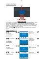
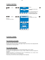
12- DISPLAY FUNCTIONS
DISPLAY FUNCTIONS
The WONDER S / WONDER D display panel shows all the available functions . Using
these functions, it is possible to change some of the parameters and add some
functions. Changing the D.T.S. setting can vary the functions of the unit so that it does
not respond to the DMX 512 used to control it. Carefully follow the instructions below
before carrying out any variations or selections.
NOTE: the symbol shows which key has to be pushed to obtain the desired
function.
Software Version: 10-11-11
Pan Direction
PAN DIRECTION
This menu allows to set
the Pan movement
Normal or Reverse
Tilt Direction
TILT DIRECTION
This menu allows to set
the Tilt movement
Normal or Reverse
Pan Speed
PAN SPEED
Pan Speed control (1-8)
Tilt Speed
TILT SPEED
Tilt Speed control (1-8)
Up-Down
Menu
Up-DownENTER
Up-Down
Menu
Up-Down
Menu
Up-DownENTER
Up-DownENTER
ENTER
ENTER
ENTER
Up-Down
Menu
Up-DownENTER
ENTER
Pan movement
Normal or Reverse
Default = Normal
Tilt movement
Normal or Reverse
Default = Normal
Pan Speed control
(1-8)
Default = 8 (Live Mode)
Tilt Speed control
(1-8)
Default = 8 (Live Mode)
MENU ENTER DOWN UP
8
LIVE-TOUR MODE
PAN SPEED
MENU ENTER DOWN UP
8
LIVE-TOUR MODE
TILT SPEED

16
MENU ENTER DOWN UP
ENABLED
BY DMX
RESET
MENU ENTER DOWN UP
34 CHANNELS
DMX MODE
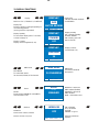
12- DISPLAY FUNCTIONS
Display
DISPLAY FLIP / STAND BY / CONTRAST
Display Flip:
Reverses display's reading depending on
the mounting position
(on the ground or suspended).
Display Standby:
To turn off the display (after 5 seconds)
or leave it always on.
Display Contrast:
Display contrast regulation (1-40)
DMX Mode
DMX MODE
To select DMX mode:
34 channels (Default) or 38 channels
Reset
RESET
Reset via DMX ENABLED / DISABLED
and unit motors reset
Wireless
WIRELESS
Wireless DMX enabled / disabled.
(Wireless module on request)
Up-Down
Menu
Up-DownENTER
ENTER
ENTER
ENTER
Up-Down
Menu
Up-DownENTER
ENTER
MENU ENTER DOWN UP
FLIP
FLIP
ON THE GROUND
DISPLAY
MENU ENTER DOWN UP
FLIP
STANDBY
OFF
DISPLAY
MENU ENTER DOWN UP
FLIP
CONTRAST
25
DISPLAY
Display Flip
ON THE GROUND (Default)
SUSPENDED
Display Standby
OFF = Display Standby
disabled (Default)
ON = Display goes OFF
after 5 seconds
Display Contrast
1-40 (Default = 25)
Up-Down
Menu
Up-DownENTER
DMX Mode
34 channels (Default)
38 channels
ENTER
ENABLED = Reset via
DMX enabled (Default)
DISABLED = Reset via
DMX disabled
NOW = Unit motors reset
Up-Down
Menu
Up-DownENTER
ENTER
ON = Enabled
OFF = Disabled
(Default)
UNLINK = Log out
(Wireless module on
request)
WIRELESS
OFF
MENU ENTER DOWN UP

17
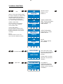
SMOOTH VALUE
Range = 0 – 20
Default = 4
GAMMA CORRECTION
LINE = Linear current output
QUAD = Quadratic light
output (Default)
OUTPUT FREQUENCY
Range: 600 Hz – 10 KHz
Default = 600 Hz
BOOST
OFF = 800mA (Default)
ON = 1000mA
SMOOTH
LED
MENU ENTER DOWN UP
4
GAMMA CORR.
LED
MENU ENTER DOWN UP
QUAD
FREQUENCY
LED
MENU ENTER DOWN UP
600 Hz
BOOST
LED
MENU ENTER DOWN UP
OFF
MENU ENTER DOWN UP
LIVE-TOUR
SETTING
LIVE-STUDIO
SYSTEM INFO
UNIT LIFE: 0124H
LED: R10
ZOOM: R11
PT: R11
MODEL: WONDER D FPR
MENU ENTER DOWN UP
RDM: 000009B4
12- DISPLAY FUNCTIONS
LED
SMOOTH: This menu allows to select
the value of the delay (in milliseconds)
for RGBW and Dimmer channels
reaction to DMX or program variation.
4 = 25 ms delay (fast response)
20 = 250 ms delay (slow response)
GAMMA CORRECTION
This menu allows to select between
Linear current output or Quadratic
current output for LEDs.
OUTPUT FREQUENCY
This menu allows to adjust the PWM
frequency value (Hz) in order to reduce
flickering in the process of your camera
recordings.
BOOST
This menu allows to increase the
LEDs current from 800mA to 1000mA.
Live-Studio setting
System Info
Up-Down
Menu
Up-DownENTER
ENTER
SYSTEM INFO
Unit life time; LED Driver,
Zoom and Pan&Tilt PCBs
software version; unit model
and RDM ID
Up-Down
Menu
Up-DownENTER
ENTER
Up-Down
Menu
Up-DownENTER
ENTER
LIVE-TOUR mode = High
fans speed: the LEDs always
work at maximum power
(Default)
STUDIO mode = Low fans
speed for a very low noise
operation

18
REBOOT
MENU ENTER DOWN UP
TEMPERATURE
CENTER: 041°C MAX CURR.
SECTOR 1: 046°C 1000 MA
SECTOR 2: 049°C
SECTOR 3: 048°C
CPU: 049°C
MENU ENTER DOWN UP
LED LIFE HOURS
CENTER S1 S2 S3
R: 0024 0024 0024 0024
G: 0024 0024 0024 0024
B: 0024 0024 0024 0024
W: 0023 0023 0023 0023
MENU ENTER DOWN UP
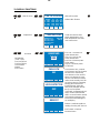
12- DISPLAY FUNCTIONS
LED Life hours
Temperature
Reserved
RESERVED
000
MENU ENTER DOWN UP
ENTER CODE
PAN LOCK
NO
MENU ENTER DOWN UP
Up-Down
Menu
Up-DownENTER
ENTER
Pan Lock = Lock the Pan
to the desired value
Tilt Lock = Lock the Tilt
to the desired value
Pan Free = Remove power
to Pan motor
Tilt Free = Remove power
to Tilt motor
LOCK DETECTOR
OFF
MENU ENTER DOWN UP
Lock Detector OFF = Default
Lock Detector ON: This function
lets the user to activate the
Lock detector on Pan and Tilt.
When Lock detector is set to
ON, the unit start the Pan&Tilt
motors reset normally, but if for
any reason there is something
blocking the movement for
Pan&Tilt motors during the
initial reset (example unit into
the fly case and power
connected), it automatically will
stop to reset Pan&Tilt motors
after 5 seconds from the startup
and a warning message (Pan
locked-Tilt locked) will appear
on unit display.
Reboot = Unit Reboot without
needing of turning OFF the unit
Exit To Main = Exit from
Reserved menu
RESERVED
(Code = 100)
Pan lock-Tilt lock
Pan free-Tilt free
Lock Detector
Reboot
Exit To Main
Up-Down
Menu
Up-DownENTER
ENTER
Center and sectors LEDs
panels temperatures; CPU
PCB temperature and LEDs
max current value
Up-Down
Menu
Up-DownENTER
ENTER
LED LIFE HOURS:
RGBW LEDs life time

19
12- DISPLAY FUNCTIONS
Demo
Default
DEFAULT
To restore main settings
13- PERIODIC CLEANING
13.1- Front lenses screen glass
The dust can reduce the luminous output substantially.
Regularly clean the front lenses screen glass using a soft cotton cloth, dampened with
a specialist lens cleaning solution.
13.2- Fans and air passages
The fans and air passages must be cleaned approximately every 6 weeks.
This periodic cleaning will depend of course, on the conditions in which the projector is
operating.
Suitable instruments for performing this type of maintenance are a brush and a
common vacuum cleaner or an air compressor.
If necessary, clean the fans and air passages more frequently.
DEFAULT
SURE?
MENU ENTER DOWN UP
RESTORE MAIN SETTINGS
DEFAULT
RESTORE MAIN SETTINGS
MENU ENTER DOWN UP
PRESS ENTER TO CONFORM
PRESS MENU TO CANCEL
Up-Down
Menu
Up-DownENTER
ENTER
Default
To restore main settings
Up-Down
Menu
Up-DownENTER
ENTER
DEMO
Demo games without DMX
controller
Pan, Tilt, Zoom effect, Zoom
speed, Dimmer, Shutter,
LED effect and LED speed
values selectable by user
DIMMER
DEMO
MENU ENTER DOWN UP
255

20
14- PERIODIC CONTROLS
Mechanical parts
Periodically check all mechanical parts, replacing them if necessary.
Electrical components
Check all electrical components for correct earthing and proper
connection of all connectors, refastening if necessary.
Fuse replacement
Locate the fuse, which protects the electronics, in the base of
the WONDER. Using a multimeter, test the condition of the
fuse, replacing it with one of equivalent type (10AT) if necessary.
!
La pagina si sta caricando...
La pagina si sta caricando...
La pagina si sta caricando...
La pagina si sta caricando...
La pagina si sta caricando...
La pagina si sta caricando...
La pagina si sta caricando...
La pagina si sta caricando...
La pagina si sta caricando...
La pagina si sta caricando...
La pagina si sta caricando...
La pagina si sta caricando...
-
 1
1
-
 2
2
-
 3
3
-
 4
4
-
 5
5
-
 6
6
-
 7
7
-
 8
8
-
 9
9
-
 10
10
-
 11
11
-
 12
12
-
 13
13
-
 14
14
-
 15
15
-
 16
16
-
 17
17
-
 18
18
-
 19
19
-
 20
20
-
 21
21
-
 22
22
-
 23
23
-
 24
24
-
 25
25
-
 26
26
-
 27
27
-
 28
28
-
 29
29
-
 30
30
-
 31
31
-
 32
32


DTS Wonder D Manuale utente
- Categoria
- Proiettori
- Tipo
- Manuale utente
- Questo manuale è adatto anche per
in altre lingue
- English: DTS Wonder D User manual