
EUPHONY 3
USER’S MANUAL rel. 1.0 GB

2
Le informazioni contenute in questo documento sono state attentamente redatte e
controllate. Tuttavia non è assunta alcuna responsabilità per eventuali inesattezze.
Tutti i diritti sono riservati e questo documento non può essere copiato, fotocopiato,
riprodotto per intero o in parte senza previo consenso scritto della D.T.S .
D.T.S. si riserva il diritto di apportare senza preavviso cambiamenti e modifiche
estetiche , funzionali o di design a ciascun proprio prodotto. D.T.S non assume alcuna
responsabilità sull’uso o sull’applicazione dei prodotti o dei circuiti descritti.
The information contained in this publication has been carefully prepared and
checked. However, no responsibility will be taken for any errors. All rights are
reserved and this document cannot be copied, photocopied or reproduced, in part or
completely, without prior written consent from D.T.S.
D.T.S. reserves the right to make any aesthetic, functional or design modifications to
any of its products without prior notice. D.T.S. assumes no responsibility for the use or
application of the products or circuits described herein.
Les informations contenues dans le présent manuel ont été rédigées et contrôlées
avec le plus grand soin. Nous déclinons toutefois toute responsabilité en cas
d'éventuelles inexactitudes. Tous droits réservés. Ce document ne peut être copié,
photocopié ou reproduit, dans sa totalité ou partiellement, sans le consentement
préalable de D.T.S.
D.T.S. se réserve le droit d'apporter toutes modifications et améliorations esthétiques,
fonctionnelles ou de design, sans préavis, à chacun de ses produits. D.T.S. décline
toute responsabilité sur l'utilisation ou sur l'application des produits ou des circuits
décrits.
Las informaciones contenidas en este documento han sido cuidadosamente
redactadas y controladas. Con todo, no se asume ninguna responsabilidad por
eventuales inexactitudes. Todos los derechos han sido reservados y este documento
no puede ser copiado, fotocopiado o reproducido, total o parcialmente, sin previa
autorización escrita de D.T.S.
D.T.S. se reserva el derecho a aportar sin previo aviso cambios y modificaciones de
carácter estético, funcional o de diseño a cada producto suyo. D.T.S. no se asume
responsabilidad de ningún tipo sobre la utilización o sobre la aplicación de los
productos o de los circuitos descritos.

3
INDEX:
1 - SYMBOLS ................................................................................................................ 4
2 - GENERAL WARNING ............................................................................................. 5
3 - GENERAL WARRANTY CONDITIONS ................................................................... 5
4 - TECHNICAL FEATURES ........................................................................................ 5
5 - ACCESSORIES ....................................................................................................... 7
6 - IMPORTANT SAFETY INFORMATION ................................................................... 8
6.1 Fire prevention...................................................................................................... 8
6.2 Prevention of electric shock .................................................................................. 8
6.3 Safety ................................................................................................................... 8
6.4 Level of protection against the penetration of solid and liquid objects .................. 8
6.5 Waste Electrical and Electronic Equipment (WEEE) directive .............................. 8
6.6 Long-life auto-charging buffer battery ................................................................... 8
7 - INSTALLATION ....................................................................................................... 9
7.1 Safety cable ........................................................................................................ 10
7.2 Protection against liquids .................................................................................... 11
7.3 Movement ........................................................................................................... 11
7.4 Risk of fire .......................................................................................................... 11
7.5 Forced ventilation ............................................................................................... 11
7.6 Ambient temperature .......................................................................................... 11
8 - MAINS CONNECTION ........................................................................................... 11
8.1 Protection ........................................................................................................... 11
9 - DMX SIGNAL CONNECTION ................................................................................ 12
9.1 DMX addresses .................................................................................................. 12
9.2 Selecting the DMX address ................................................................................ 12
10 - RDM FUNCTIONS ............................................................................................... 13
11 - FIRMWARE UPDATING ...................................................................................... 16
12 - DISPLAY FUNCTIONS ........................................................................................ 17
13 - ERROR MESSAGES ........................................................................................... 24
14 - SOFT FROST FILTER INSTALLATION .............................................................. 26
15 - PERIODIC CLEANING ........................................................................................ 26
15.1 Lenses and reflectors ....................................................................................... 26
15.2 Fans and air passages ..................................................................................... 26
16 - PERIODIC CONTROLS ....................................................................................... 27
17 - DMX PROTOCOL ................................................................................................ 35

4
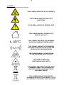
1- SYMBOLS
Graphic symbols used on this manual:
THIS SYMBOL INDICATES A HOT SURFACE
THIS SYMBOL INDICATES ELECTRIC
SHOCK RISK
THIS SYMBOL INDICATES GENERAL RISK
THIS SYMBOL MEANS “SUITABLE FOR
INDOOR USE ONLY”
THIS SYMBOL INDICATES THE MAXIMUM
OPERATING AMBIENT TEMPERATURE
THIS SYMBOL INDICATES THE MINIMUM
DISTANCE FROM THE OBJECTS AND THE
PEOPLE LIT BY THE LIGHT BEAM
THIS SYMBOL MEANS “DO NOT STARE
AT THE OPERATING LIGHT SOURCE”
THIS SYMBOL INDICATES
PHOTOBIOLOGICAL SAFETY
THIS SYMBOL INDICATES THE EUROPEAN
COMMUNITY DIRECTIVE 2012/19/EU ON
WASTE ELECTRICAL AND ELECTRONIC
EQUIPMENT (WEEE)
THIS SYMBOL MEANS “DISPOSE THE
INTERNAL BATTERY AT THE END OF ITS LIFE
ACCORDING TO THE REGULATION IN FORCE”
!

5
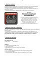
2- GENERAL WARNING
Read the instruction contained in this user manual carefully, as they give important
information regarding safety during installation, use and maintenance.
The unit is not for household use and must be installed by a qualified electrician or
experienced person.
The device must always be equipped with an efficient ground connection.
3- GENERAL WARRANTY CONDITIONS
The unit is guaranteed for 36 months from the date of purchase against manufacturing
material defects.
The warranty covers defects in materials and workmanship. The warranty is not
appliable where a defect is caused by misuse or unauthorised repair of the product.
Any functional or/and physical modification of the product is not allowed.
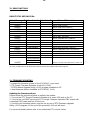
4- TECHNICAL FEATURES
DTS Product Code:
03.LDR020.F EUPHONY 3
OUTPUT
• 7 x 60W Full Color (RGBW) LEDs
• 7500 Lumen output
• LEDs lifespan: 50.000 hours (70% lumen output)
OPTICAL GROUP
• 5.6° - 69° linear motorized zoom with high efficiency optical system
• Soft frost filter included
• Uniform projection on surfaces, from very wide Wash to PC Beam
WARNING!
NEVER EXPOSE THE FRONT LENS
TO SUNLIGHT FROM ANY ANGLE
TO AVOID DAMAGE OF
HEAD INTERNAL PARTS.
Front lens could become powerful magnifying
glass if exposed towards the sun or any
strong artificial light source; this can cause
damage of head internal parts, even for few
seconds and even when the unit is off.
The last command before switch off:
point the front lens down towards the ground.

6
4- TECHNICAL FEATURES
COLOR GENERATION
• 16 million colors
• Wide palette of pure uniform whites with variable linear color temperature (2700K –
8000K)
• 16 gel filters emulations by ‘Standard’ DMX mode
DIMMER
• Hi-Q Dimming technology
CONTROL
• LCD graphic display + 4 soft keys; Auto-flip; Key-lock function
• RDM/DMX 512 protocols
• Wireless DMX available on request
• ‘Standard’ and ‘Silent’ operation modes
• Internal operating system updatable via DTS dongle firmware uploader
• Li-Fe backup battery for controlling the display settings even when the unit is not
powered
DMX
• 2 DMX modes:
- 1. Standard 18 ch (default)
- 2. Compatibility 20 ch
PAN & TILT
• Pan 540° (1.8 sec.)
• Tilt 215° (1 sec.)
• 16-bit resolution
POWER SUPPLY
• Full-range 100-240Vac 50-60 Hz
• Power consumption: 420W max
• Power Factor: PF >0.94
CONNECTIONS
• Power supply: powerCON TRUE1 In/Out panel connectors
• DMX: XLR 3-pole and 5-pole In/Out panel connectors
INTERNAL SAFETY DEVICES
Overvoltage and overtemperature circuits protection
OPERATING TEMPERATURE
-10° / 40°C
PHYSICAL
• IP20
• Weight: 14 Kg
• Finishing: Black
CERTIFICATIONS

7
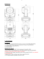
DIMENSIONS
5- ACCESSORIES
As standard
1 x Cable with PowerCON TRUE1 female connector (Code 02K0012267.0015)
1 x Omega bracket with “Fast Lock” connection 1/4 turn (Code 02K00467)
1 x Soft frost filter (code 02SK0472)
1 x User’s manual
Optional (on request)
• Lumen Radio Wireless DMX TX-RX interface kit (Code 03.LA.241)
• Aliscaf clamp for tube diameter 48-51 mm (Max load 200 Kg) (code 0521A033)
(indicated for any kind of loads vertical / horizontal)
• Professional Quick trigger clamp (Max load 100 Kg) (code 0521A037) (not indicated
for horizontal load)
• Safety cable 3 x 600 mm (Max load 30 Kg) (code 0521A010)
• DTS Dongle firmware uploader (code 03.LA.206

8
6- IMPORTANT SAFETY INFORMATION
6.1 Fire prevention:
-Minimum distance from the objects and the people lit by the light beam: 0,5 m.
-Replace any blown or damaged fuses only with those of identical value (T 5A 250V). Refer to
the wiring diagrams if there is any doubt.
-Connect the projector to mains power via a thermal magnetic circuit breaker.
6.2 Prevention of electric shock:
-High voltage is present inside the unit.
Unplug the unit prior to performing any function which involves touching the inside of the
moving head.
-The level of technology inherent in the EUPHONY 3 requires the assistance of specialised
personnel for all servicing. Please refer to an authorised DTS service centre.
-A good earth connection is essential for proper functioning of the projector.
-Never connect the unit without proper earth connection.
-The fixture should be located in places with a good air ventilation.
6.3 Safety:
-Risk Group 2 product according to IEC 62471.
CAUTION. Do not look directly into the light output and do not view the light beam with optical
instruments or any device that may concentrate the beam.
May be harmful to the eyes and skin.
-Do not stare at the operating light source.
-The light source contained in this luminaire shall only be replaced by the manufacturer or his
service agent or a similar qualified person.
-The unit is not for household use and must be installed by a qualified electrician or
experienced person.
-The projector should always be installed with bolts, clamps and other tools that are capable
of supporting the weight of the unit.
-Always use a safety cable to sustain the weight of the unit in case of the failure of the main
fixing point.
-The external surface of the unit, at various points, may exceed 50°C. Never handle the unit
until at least 5 minutes have elapsed since the unit was turned off.
-Never install the fixture in an enclosed area lacking sufficient air flow.
The ambient temperature should not exceed 40°C.
6.4 Level of protection against the penetration of solid and liquid objects:
-The projector is classified as an ordinary appliance and its protection level against the
penetration of solid and liquid objects is IP20.
Suitable for indoor use only.
6.5 Waste Electrical and Electronic Equipment (WEEE) directive:
- The projector, accessories and packaging should be sorted for environmental-friendly
recycling.
For EC countries: according to the European Directive 2012/19/EU for Waste Electrical and
Electronic Equipment and its implementation into national right, luminaires that are no longer
usable must be collected separately and disposed of in an environmentally correct manner.
6.6 Long-life auto-charging buffer battery:
-The projector contains a rechargeable lead-acid or lithium iron tetraphosphate battery.
To preserve the environment, please dispose the battery at the end of its life according to the
regulation in force.
!
!

9
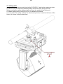
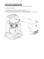
7- INSTALLATION
The unit is suitable for dry locations only.
EUPHONY 3 may be either floor or ceiling mounted.
For floor mounting installations, EUPHONY 3 is supplied with four rubber mounting
feet on the base.
For ceiling mounted installations, we recommend the use of appropriate clamps to fix
the unit to the mounting surface.
The supporting structure from which the unit is hung should be capable of bearing the
weight of the unit, as should any clamps used to hang it.
The structure should also be sufficiently rigid so as not to move or shake whilst the
EUPHONY 3 is moving.
Four 1/4 turn Fast Locks connections placed in the base of the unit allow to hang the
EUPHONY 3 by using a Omega bracket (provided in the box) in conjunction with
Aliscaf clamp (available on demand).

10
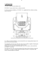
7.1- Safety cable
A safety cable must be securely fixed to the EUPHONY 3 and to the suspension truss
in order to avoid the fixture accidentally falling should the main fixing point fail.
Make sure that the safety cable or chain can bear the weight of the entire unit.
A suitable safety cable (code 0521A010) is available on demand.
You may attach the safety cable to the attachment point (A) located on the base of the
fixture, as shown in the picture below.

11
7.2 Protection against liquids
The projector contains electric and electronic components which should under no
circumstances come into contact with oil, water or any other liquid.
The proper unit functioning would be compromised should this occur.
7.3- Movement
Pan: 540° rotation (1.8 sec.) ; Tilt: 215° rotation (1 sec.).
Do not place any object in the path of the projector’s movement.
7.4- Risk of fire
Each fixture produces heat and must be installed in a well-ventilated place.
Minimum distance from the objects and the people lit by the light beam: 0,5 m.
7.5- Forced ventilation
You will note, on inspection, that the unit features various air inlets and cooling fans
located on both the base and head of the fixture.
These should, under no circumstances, be blocked or obstructed whilst the projector
is in operation. Doing so could cause the fixture to seriously overheat thereby
compromising its proper operation.
7.6- Ambient temperature
The projector should never be installed in places that lack a constant air flow.
The ambient temperature should not exceed 40°C.
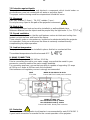
8- MAINS CONNECTION
EUPHONY 3 operates at 100-240Vac 50-60 Hz.
Prior to connecting the unit to your mains supply, ensure that the model in your
possession correctly matches the mains supply available.
For connection purposes, ensure that your plug is capable of supporting 2,5 amps
at 230Vac or 5 amps at 100Vac each unit connected.
Strict adherence to regulatory norms is strongly recommended.
FUSE MAINS IN 100-240Vac 50-60 Hz
T 5A 250V PowerCON TRUE1 male panel connector
MAINS OUT MAX 16A
Max 6 EUPHONY units @ 230Vac
Max 3 EUPHONY units @ 100Vac
PowerCON TRUE1 female panel connector
8.1- Protection
The use of a thermal magnetic circuit breaker is recommended for each EUPHONY 3.
A good earth connection is essential for the correct operation of the projector.
!
!

12
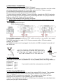
9- DMX SIGNAL CONNECTION
The unit operates using the digital DMX 512 signal.
Connection between the mixer and the projector or between projectors must be carried
out using a two pair screened ø 0.5 mm cable and a XLR 5 or 3 pins connector.
Ensure that the conductors do not touch each other.
Do not connect the cable ground to the XLR chassy.
The plug housing must be isolated. Connect the mixer signal to the DMX IN projector
plug and connect it to the next projector by connecting the DMX OUT plug on the first
projector to the DMX IN plug of the second one.
This way, all the projectors are cascade connected.
NB. If the display showing the DMX address flashes, then one of the following errors
has occurred:
- DMX signal not present
- DMX reception problem
For Installations where long distance DMX cable connections are needed, we suggest
to use a DMX terminator.
The DMX terminator is a male XLR 3-5 pins connector with a 120 ohm resistor
between pin 2 and 3.
The DMX terminator must be plugged into the last unit (DMX out panel connector) of
the DMX line.
PLACE A 120 OHM RESISTOR BETWEEN PIN 2
AND 3 OF A MALE XRL CONNECTOR AND PLUG IT
INTO THE DMX OUT PANEL CONNECTOR OF THE
LAST UNIT CONNECTED TO THE DMX LINE
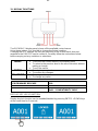
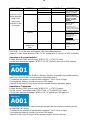
9.1-DMX Addresses
EUPHONY 3 can be used in “Standard 18 ch” or “Compatibility 20 ch” DMX mode.
In order to use the unit in “Standard 18 ch” mode (Default), set the following addresses
on the mixer:
Projector 1 A001
Projector 2 A019 If you want to select the next projector, just add “18”
Projector 3 A037
….. A….
projector 6 A091
9.2-Selecting the DMX address
1) Press the UP-DOWN key until you reach the required DMX channel. The numbers
on the display will start to flash (but the new DMX address hasn't yet been set).
2) Press ENTER to confirm your selection. The numbers on the display will stop
flashing and the projector is now setted to the new DMX address.
TRICKS: If you keep pushed the UP or DOWN keys, the channels are calculated more
quickly and you get a faster selection.
1
2
3
5
4
OUT
120 ohm
PIN 3
PIN 2

13
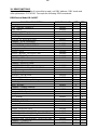
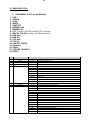
10- RDM FUNCTIONS
By using a RDM controller it is possible to read / set DMX address, DMX mode and
other parameters. EUPHONY 3 accepts the following RDM commands:
RDM Device Model ID: 0x0017
RDM PID DESCRIPTION
RDM PID VALUE
GET
SET
Category – Network Management
DISC_UNIQUE_BRANCH
0x0001
DISC_MUTE
0x0002
DISC_UN_MUTE
0x0003
Category – Status Collection
STATUS_MESSAGES
0x0030
X
STATUS_ID_DESCRIPTION
0x0031
X
Category - RDM Information
SUPPORTED_PARAMETERS
0x0050
X
PARAMETERS_DESCRIPTION
0x0051
X
Category – Product Information
DEVICE_INFO
0x0060
X
DEVICE_MODEL_DESCRIPTION
0x0080
X
MANUFACTURER_LABEL
0x0081
X
DEVICE_LABEL
0x0082
X
X
SOFTWARE_VERSION_LABEL
0x00C0
X
Category - DMX512 Setup
DMX_PERSONALITY
0x00E0
X
X
DMX_PERSONALITY_DESCRIPTION
0x00E1
X
DMX_START_ADDRESS
0x00F0
X
X
Category – Sensors
SENSOR_DEFINITION
0x0200
X
SENSOR_VALUE
0x0201
X
X
Category – Power/Lamp Settings
DEVICE_HOURS
0x0400
X
LAMP_HOURS
0x0401
X
Category – Display Settings
DISPLAY_INVERT
0x0500
X
X
Category – Configuration
PAN_INVERT
0x0600
X
X
TILT_INVERT
0x0601
X
X
Category – Control
IDENTIFY_DEVICE
0x1000
X
X
Category – Dimmer Settings
CURVE
0x0343
X
X
CURVE_DESCRIPTION
0x0344
X
OUTPUT_RESPONSE_TIME
0x0345
X
X
OUTPUT_RESPONSE_TIME_DESCRIPTION
0x0346
X
MODULATION_FREQUENCY
0x0347
X
X
MODULATION_FREQUENCY_DESCRIPTION
0x0348
X
Category – Custom PID
DISPLAY_STANDBY
0x8002
X
X

14
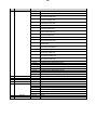
15- RDM FUNCTIONS
RDM ADDITIONAL MESSAGEs:
CURVE
CURVE DESCRIPTION
1
LINEAR
2
QUADRATIC (default)
3
GAMMA 2.2
4
S-CURVE
OUTPUT RESPONSE TIME
OUTPUT_RESPONSE_TIME_DESCRIPTION
1
SMOOTH OFF
2
SMOOTH 1 ( 25 ms)
3
SMOOTH 2 ( 50 ms)
4
SMOOTH 3 ( 75 ms)
5
SMOOTH 4 (100 ms) (default)
6
SMOOTH 5 (125 ms)
7
SMOOTH 6 (150 ms)
8
SMOOTH 7 (175 ms)
9
SMOOTH 8 (200 ms)
10
SMOOTH 9 (225 ms)
11
SMOOTH 10 (250 ms)
12
SMOOTH 11 (275 ms)
13
SMOOTH 12 (300 ms)
14
SMOOTH 13 (325 ms)
15
SMOOTH 14 (350 ms)
16
SMOOTH 15 (375 ms)
17
SMOOTH 16 (400 ms)
18
SMOOTH 17 (425 ms)
19
SMOOTH 18 (450 ms)
20
SMOOTH 19 (475 ms)
21
SMOOTH 20 (500 ms)

15
15- RDM FUNCTIONS
RDM ADDITIONAL MESSAGEs:
MODULATION FREQUENCY
MODULATION FREQUENCY DESCRIPTION
1
610 Hz
2
800 Hz
3
1.000 Hz (default)
4
1.500 Hz
5
2.000 Hz
6
2.500 Hz
7
3.000 Hz
8
3.500 Hz
9
4.000 Hz
10
4.500 Hz
11
5.000 Hz
RDM MANUFACTURER’S SPECIFIC PIDs:
RDM CUSTOM PID
DESCRIPTION
0x8002_DISPLAY_STANDBY
Set parameter DISPLAY – STANDBY
0 = DISABLED (default)
1 = ENABLED
2 = FORCED ENABLED

16
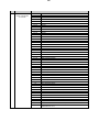
15- RDM FUNCTIONS
RDM STATUS MESSAGE IDs:
Status Message ID
Data Value 1
Data Value 2
Status ID Description
0x8000
ERROR PAN MOTOR/ENCODER
0x8001
ERROR PAN LOCKED
0x8002
ERROR PAN ZERO SENSOR
0x8003
ERROR TILT MOTOR/ENCODER
0x8004
ERROR TILT LOCKED
0x8005
ERROR TILT ZERO SENSOR
0x8006
ERROR DMX ADDRESS
0x8007
ERROR PARAMETERS MEMORY
0x8008
ERROR SUPPLY VOLTS TOO LOW
0x8009
ERROR SUPPLY VOLTS TOO HIGH
0x800B
ERROR BUS LED DRIVER CARD
0x800C
card number
ERROR BUS MOTORS CARD %d
0x801F
ERROR TEMPERATURE LED MODULE
0x8020
sensor number
ERROR TEMPERATURE LED DRIVER %d
0x8021
ERROR TEMPERATURE MICRO
0x8027
sensor number
ERROR TEMPERATURE SENSOR %d
0x8028
1=data not present
ERROR COLOUR DATA INTEGRITY CODE %d*
2=read error
3=incomplete data
*In case of LED Driver PCB replacement will be shown these RDM Status Message IDs.
11- FIRMWARE UPDATING
To update the firmware release of the EUPHONY 3 you need:
- DTS Dongle Firmware Uploader (code 03.LA.206).
- “DTS Firmware Upgrade Utility v.2.02” program installed on PC.
- Latest firmware release available for EUPHONY 3 unit.
Updating the firmware release.
Please follow the procedure below to perform the update:
1. Connect the DTS Dongle Firmware Uploader to a spare USB port on the PC.
2. Connect the unit DMX input to the DTS Dongle Firmware Uploader DMX output with
a standard DMX cable and turn ON the unit.
3. Send the new firmware release into the unit by using “DTS Firmware Upgrade
Utility v.2.02” program. At the end of the procedure, the unit will reset.
For more information please refer to an authorised DTS service centre.

17
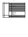
12- DISPLAY FUNCTIONS
The EUPHONY 3 display panel shows all the available control menus.
Using these options, it is possible to change the fixture’s setting.
Changing the DTS settings can vary the functions of the unit so that it does not
respond to the DMX 512 used to control it. Carefully follow the instructions below
before carrying out any variations or selections.
MENU
• To access the control menus in the display panel.
• To return to the previous level in the menu structure without
making a change.
• To exit the menus.
ENTER
• To select any required menu.
• To confirm any changes.
UP / DOWN
• To navigate the menus structure.
• To change any value.
MOTORS FIRMWARE RELEASE
LED FIRMWARE RELEASE
12
1.00
RDM Device Model ID
0x0017
DMX Personality IDs
0x01 “STANDARD 18CH”
0x02 “COMPATIBILITY 20CH”
DISPLAY KEY-LOCK FUNCTION
Display key-lock function can be enabled/disabled by pressing ENTER + DOWN keys
at the same time for 3 seconds.

18
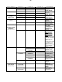
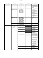
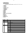
MAIN MENU
LEVEL 1
LEVEL 2
LEVEL 3
FUNCTION
PAN DIRECTION
NORMAL
Allows to set the Pan
movement.
Normal or Reverse.
Normal (Default).
REVERSE
TILT DIRECTION
NORMAL
Allows to set the Tilt
movement.
Normal or Reverse.
Normal (Default).
REVERSE
ZOOM
DIRECTION
NORMAL
Allows to set the Zoom
movement.
Normal or Reverse.
Normal (Default).
REVERSE
OPERATING
MODE
STANDARD
Pan-Tilt-Zoom-Fans
standard speed
(Default).
SILENT
Reduced Pan-Tilt-
Zoom-Fans speed for
low noise operation.
FAN MODE
(FAN MODE will work
relatively to
OPERATING MODE)
CONSTANT
Same fans speed in
any working
condition in SILENT
or STANDARD
operating mode
(Default).
AUTOMATIC
Automatic fans speed.
If LED temperature
<40°C: fans OFF.
If LED temperature
>40°C:
If OPERATING MODE
= SILENT, fans speed
is increased within the
values range set in
SILENT mode.
If OPERATING MODE
= STANDARD, fans
speed is increased
within the values range
set in STANDARD
mode.
DISPLAY
FLIP
AUTO
Reverses display’s
reading depending on
the mounting position.
Automatic, on the
ground or suspended.
Automatic (Default).
ON THE
GROUND
SUSPENDED
STANDBY
DISABLED
Display stand-by
disabled (Default).
ENABLED
Display goes OFF after
5 seconds.
FORCED
ENABLED
Display forced OFF
even if control signal is
missing or error
messages are shown.
CONTRAST
20 - 35
Display contrast
regulation.
Range 20-35.
Default = 25.
DMX MODE
Personality
STANDARD
18 channels
Allows to select
STANDARD mode
(18 DMX channels).
Default.
COMPATIBILITY
20 channels
Allows to select
COMPATIBILITY
mode (20 DMX
channels).

19
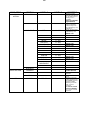
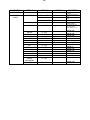
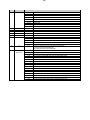
MAIN MENU
LEVEL 1
LEVEL 2
LEVEL 3
FUNCTION
NO DMX
ACTION
KEEP LAST DMX
Allows to set the
desired unit’s behavior
in case DMX signal is
missing or not
available.
Keep last valid DMX
signal (Default).
PROGRAM 1-48
1 - 48
48 pre-programmed
steps. Speed time
values (range 0.5x –
3x) selectable by user
(default 1x).
SINGLE CUE
RED
0 - 255
Fixed cue with values
selectable by user.
Default = 255
GREEN
0 - 255
Default = 255
BLUE
0 - 255
Default = 255
WHITE
0 - 255
Default = 255
SHUTTER
0 - 255
Default = 15
DIMMER MSB
0 - 255
Default = 255
DIMMER LSB
0 - 255
Default = 255
CCT
0 - 255
Default = 0
MACRO COLOR
0 - 255
Default = 0
PAN MSB
0 - 255
Default = 128
PAN LSB
0 - 255
Default = 128
TILT MSB
0 - 255
Default = 128
TILT LSB
0 - 255
Default = 128
SPEED
MOVEMENT
0 - 255
Default = 0
ZOOM
0 - 255
Default = 128
BLACKOUT
Black-out.
RESET BY DMX
ENABLED
Reset via DMX
enabled (Default).
DISABLED
Reset via DMX
disabled.
NOW
Instant unit motors
reset.
LED
SMOOTH
OFF - 20
Allows to select the
value of delay (in ms)
for DIMMER channel
reaction to DMX
dimming command.
OFF = Instant
response.
4 = 100 ms smooth
response (Default).
20 = 500 ms smooth
response.

20
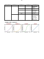
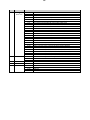
MAIN MENU
LEVEL 1
LEVEL 2
LEVEL 3
FUNCTION
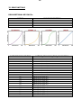
LED
GAMMA CORR.
QUAD 2.0
Allows to set
quadratic current
output for LED
(Default).
2.2
Allows to set gamma
curve 2.2 .
S-CURVE
Allows to set S-curve
to emulates light
intensity characteristics
of the tungsten
halogen lamps.
LINE
Allows to set linear
light output.
FREQUENCY
610 - 5000 HZ
Allows to adjust the
PWM frequency value
(Hz) in order to reduce
flickering in the
process of your
camera recordings.
Range = 610 Hz – 5
KHz
Default = 1000 Hz
“GAMMA CORR.” GRAPHICS:
La pagina si sta caricando...
La pagina si sta caricando...
La pagina si sta caricando...
La pagina si sta caricando...
La pagina si sta caricando...
La pagina si sta caricando...
La pagina si sta caricando...
La pagina si sta caricando...
La pagina si sta caricando...
La pagina si sta caricando...
La pagina si sta caricando...
La pagina si sta caricando...
La pagina si sta caricando...
La pagina si sta caricando...
La pagina si sta caricando...
La pagina si sta caricando...
-
 1
1
-
 2
2
-
 3
3
-
 4
4
-
 5
5
-
 6
6
-
 7
7
-
 8
8
-
 9
9
-
 10
10
-
 11
11
-
 12
12
-
 13
13
-
 14
14
-
 15
15
-
 16
16
-
 17
17
-
 18
18
-
 19
19
-
 20
20
-
 21
21
-
 22
22
-
 23
23
-
 24
24
-
 25
25
-
 26
26
-
 27
27
-
 28
28
-
 29
29
-
 30
30
-
 31
31
-
 32
32
-
 33
33
-
 34
34
-
 35
35
-
 36
36


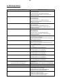
in altre lingue
- English: DTS EUPHONY 3 User manual
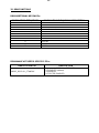
Documenti correlati
-
 DTS Portfolio Manuale utente
-
 DTS X-BRICK Manuale utente
-
 DTS Synergy 5 Spot Manuale utente
-
 DTS SCENA LED 120 HQS Manuale utente
-
 DTS JED Manuale utente
-
 DTS Katana Manuale utente
-
 DTS SCENA LED 200 MZ FC Manuale utente
-
 DTS Nick Wash 600 Manuale utente
-
 DTS Brick Manuale utente
-
 DTS 03.MS014.EBLFP Manuale utente


