Ghibli & Wirbel POWER TOOL PRO FD 50 P EL Use And Maintenance
- Categoria
- Aspirapolvere
- Tipo
- Use And Maintenance

www.ghibliwirbel.com
Professional Cleaning Machines Since 1968
POWER LINEPOWER LINE
POWER TOOLPOWER TOOL
8050814
ed. 04/2022
IT
Uso e Manutenzione
EN
Use and Maintenance
FR
Utilisation et Entretien
DE
Gebrauch und Wartung
ES
Uso y Mantenimiento
PT
Uso e manutenção
NL
Gebruik en Onderhoud
CS
RU
AR
Copertina POWER LINE_8050814_5ed_04-2022.indd 1Copertina POWER LINE_8050814_5ed_04-2022.indd 1 06/04/2022 14:19:3306/04/2022 14:19:33

www.ghibliwirbel.com
Professional Cleaning Machines Since 1968
2
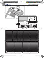
1 2 3 4 5
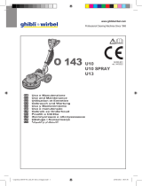
IT
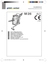
Produttore Modello Articolo Capacità contenitore Capacità aspirazione
EN
Manufacturer Model Article Container capacity Vacuum
FR
Producteur Modèle Article Capacité de la cuve Capacité d’aspiration
DE
Hersteller Modell Artikel
Fassungsvermögen des Körpers
Ansaugleistung
ES
Fabricante Modelo Artículo Capacidad del bidón Capacidad de aspiración
PT
Produtor Modelo Artigo Capacidade do reservatório Capacidade de aspiração
NL
Producent Model Artikel Inhoud reservoir Zuigcapaciteit
CS
Výrobce Model Typ Obsah nádoby Sací výkon
RU
Изготовитель Модель Артикул Емкость бака Мощность всасывания
PL
Producent Model Artykuł Pojemność zbiornika Podciśnienie (mbar)
AR
6 7 8 9
IT
Portata d’aria Peso macchina N° Matricola Caratteristiche elettriche
EN
Air flow Machine weight Serial N° Electrical characteristics
FR
Débit d’air Poids de la machine N° Matricule Caractéristiques électriques
DE
Luftdurchsatz Maschinengewicht Serien-Nr. Elektrische Eigenschaften
ES
Caudal de aire Peso de la máquina N° Matrícola Características eléctricas
PT
Caudal de ar Peso da máquina Número de série Características elétricas
NL
Luchtdebiet Machine gewicht Serienummer Elektrische eigenschappen
CS
Množství dopravovaného vzduchu
Hmotnost stroje Výrobní č. Elektrické údaje
RU
Расход воздуха Вес машины Заводской № Электрические характеристики
PL
Przepływ powietrza Ciężar maszyny Nr. Fabryczny Właściwości elektryczne
AR
Art.:
MADE IN ITALY
IPX4
Year:
Mod:Wet & Dry Vac
Air flow:Cap.ty:
S/N:Weight:
Vac.:
3
87 5 64
1
9
2
Copertina POWER LINE_8050814_5ed_04-2022.indd 2Copertina POWER LINE_8050814_5ed_04-2022.indd 2 06/04/2022 15:25:0106/04/2022 15:25:01

www.ghibliwirbel.com
Professional Cleaning Machines Since 1968
3
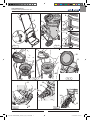
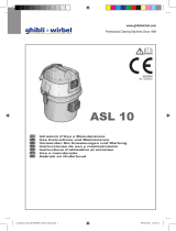
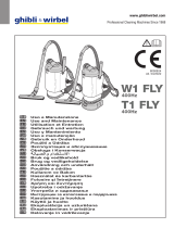
Fig. 1 Fig. 2
Fig. 6
3
4
1
2
10
11
Fig. 5
11
13 14
12
14
16
Fig. 7
15
16
15
Fig. 3
Fig. 4
6
7
5
8
8
9
46
9
46
Copertina POWER LINE_8050814_5ed_04-2022.indd 3Copertina POWER LINE_8050814_5ed_04-2022.indd 3 06/04/2022 14:19:3806/04/2022 14:19:38

www.ghibliwirbel.com
Professional Cleaning Machines Since 1968
4
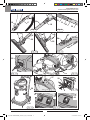
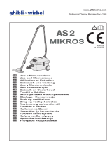
Fig. 10
Fig. 9
Fig. 13
20
20
19
21 22
20
Fig. 8
17
19 18
19
25
24
23
Fig. 11
Fig. 12
Fig. 14
27
Fig. 15
29
Fig. 16
30
31 32
Fig. 17
47
48
49
50
51
52
26
28
Copertina POWER LINE_8050814_5ed_04-2022.indd 4Copertina POWER LINE_8050814_5ed_04-2022.indd 4 06/04/2022 14:19:3906/04/2022 14:19:39

www.ghibliwirbel.com
Professional Cleaning Machines Since 1968
5
Fig. 19Fig. 18 Fig. 20
38
37
35
Fig. 21
Fig. 23 Fig. 22 Fig. 24
Fig. 25
39 35
40
35 40
Fig. 26
Fig. 27
57
53 54
15 33
34
36
36
35
Copertina POWER LINE_8050814_5ed_04-2022.indd 5Copertina POWER LINE_8050814_5ed_04-2022.indd 5 06/04/2022 14:19:3906/04/2022 14:19:39

www.ghibliwirbel.com
Professional Cleaning Machines Since 1968
6
Fig. 29
41
42
Fig. 30
43
Fig. 31
44
Fig. 32
Fig. 33
45
Fig. 34 Fig. 35
9
46
9
46
Fig. 28
55
56
56
58
58
58
Copertina POWER LINE_8050814_5ed_04-2022.indd 6Copertina POWER LINE_8050814_5ed_04-2022.indd 6 06/04/2022 14:19:3906/04/2022 14:19:39

www.ghibliwirbel.com
Professional Cleaning Machines Since 1968
7
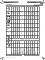
D 22.1 -
220 - 240 V~ 50/60 Hz
800 W 1000 W 58 ±2 db(A) 230 mbar 11 l 500 x 380 x
485 mm
8,5 kg (P)
9,1 kg (I) Ø 36 mm
WD 22.1 UFS 1100 W - 60 ±2 db(A) 235 mbar 11 l 500 x 380 x
590 mm
11,3 kg (P)
12,3 kg (I) Ø 36 mm
PRO FD 22.1 P EL 1100 W 3100 W 60 ±2 db(A) 235 mbar 11 l 500 x 380 x
640 mm 11,3 kg Ø 36 mm
WD 36.1 UFS
D 36.1 1100 W - 60 ±2 db(A) 235 mbar 25 l 500 x 380 x
770 mm
12 kg (P)
13 kg (I) Ø 40 mm
PRO FD 36.1 I COMBI
PRO FD 36.1 I EL
PRO FD 36.1 P COMBI
PRO FD 36.1 P EL
1100 W 3100 W 60 ±2 db(A) 235 mbar 25 l 500 x 380 x
820 mm
12 kg (P)
13 kg (I) Ø 40 mm
WD 50.1 UFS
D 50.1 1350 W - 62 ±2 db(A) 260 mbar 35 l 540 x 490 x
840 mm
14,3 kg (P)
15,3 kg (I) Ø 40 mm
PRO FD 50.1 P COMBI
PRO FD 50.1 P EL 1350 W 3350 W 62 ±2 db(A) 260 mbar 35 l 540 x 490 x
840 mm 15 kg Ø 40 mm
WD 80.2 UFS 2200 W - 62 ±2 db(A) 225 mbar 56 l 660 x 520 x
920 mm
21,7 kg (P)
23 kg (I) Ø 40 mm
WD 80.2 I TMT UFS 2200 W - 62 ±2 db(A) 225 mbar 56 l 740 x 580 x
1010 mm 23,8 kg (I) Ø 40 mm
WD 80.2 TPT UFS 2200 W - 62 ±2 db(A) 225 mbar 56 l 650 x 520 x
955 mm
22,5 kg (P)
23,8 kg (I) Ø 40 mm
D 80.2 P 2200 W - 62 ±2 db(A) 225 mbar 56 l 660 x 520 x
920 mm
21,7 kg (P)
23 kg (I) Ø 40 mm
WD 90.2 PD SP UFS 2200 W - 62 ±2 db(A) 225 mbar 56 l 620 x 530 x
950 mm 24,5 kg (P) Ø 40 mm
Copertina POWER LINE_8050814_5ed_04-2022.indd 7Copertina POWER LINE_8050814_5ed_04-2022.indd 7 06/04/2022 14:20:4806/04/2022 14:20:48

D 22.1
-
220 - 240 V~ 50/60 Hz
800 W
WD 22.1 UFS
PRO FD 22.1 P EL
1100 W
WD 36.1 UFS
D 36.1
PRO FD 36.1 I COMBI
PRO FD 36.1 I EL
PRO FD 36.1 P COMBI
PRO FD 36.1 P EL
1100 W
WD 50.1 UFS
D 50.1
PRO FD 50.1 P COMBI
PRO FD 50.1 P EL
1350 W
WD 80.2 UFS
2200 W
WD 80.2 I TMT UFS
2200 W
WD 80.2 TPT UFS
2200 W
D 80.2 P
2200 W
WD 90.2 PD SP UFS
2200 W
Copertina POWER LINE_8050814_5ed_04-2022.indd 8Copertina POWER LINE_8050814_5ed_04-2022.indd 8 06/04/2022 14:20:4806/04/2022 14:20:48

www.ghibliwirbel.com
Professional Cleaning Machines Since 1968
9
IT Italiano ................................................................................................... ITALIANO -1
(Istruzioni originali)
EN English ...................................................................................................ENGLISH -1
(Translation of original instructions)
FR Français .............................................................................................. FRANÇAIS -1
(Traduction des instructions d’origine)
DE Deutsch ................................................................................................ DEUTSCH -1
(Übersetzung der Originalanleitung)
ES Español .................................................................................................ESPAÑOL -1
(
Traducción de las instrucciones originales
)
PT Português ........................................................................................ PORTUGUÊS -1
(Tradução das instruções originais)
NL Nederlands ....................................................................................NEDERLANDS -1
(Vertalinig van de originele instructies)
CS ........................................................................................................ -1
(Překladoriginálníhonávodu)
RU ................................................................................................ -1
AR ...................................................................................................................... 1 -
( )
Copertina POWER LINE_8050814_5ed_04-2022.indd 9Copertina POWER LINE_8050814_5ed_04-2022.indd 9 06/04/2022 14:20:5406/04/2022 14:20:54

Copertina POWER LINE_8050814_5ed_04-2022.indd 10Copertina POWER LINE_8050814_5ed_04-2022.indd 10 06/04/2022 14:20:5406/04/2022 14:20:54

www.ghibliwirbel.com
Professional Cleaning Machines Since 1968
ITALIANO -
1
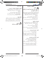
INTRODUZIONE
PERICOLO:
Prima di utilizzare la macchina
leggere attentamente il libretto
“AVVERTENZE DI SICUREZZA
PER ASPIRATORI” allegato al
presente.
TIPO D’USO
Questi apparecchi sono stati concepiti per
aspirare solidi o liquidi o entrambi come da
tabella dati tecnici presente nella parte intro-
duttiva del manuale. Solo per questi utilizzi
sono stati concepiti.
PERICOLO:
Il costruttore non può essere
ritenuto responsabile per even-
tuali danni dovuti ad un uso im-
proprio o scorretto.
Qualsiasi altro utilizzo solleva
il costruttore da responsabilità
per danni a persone e/o cose e
fa decadere qualsiasi condizio-
ne di garanzia.
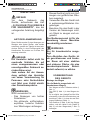
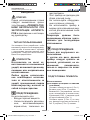
AVVERTENZA:
Non utilizzare l’apparecchio per:
- Aspirare sostanze calde.
- Non aspirare sostanze/misce-
le incandescenti, infiammabili,
esplosive, tossiche.
- Questo apparecchio non è adat-
to a raccogliere polveri pericolo-
se.
- Non utilizzare l’apparecchio in
ambienti con rischio di esplosio-
ne.
- Non utilizzare l’apparecchio in
versione aspiraliquidi per aspira-
re polveri e viceversa.
Gli operatori devono essere ade-
guatamente istruiti all’uso di
questa macchina.
AVVERTENZA:
Solo per uso interno.
Questo apparecchio deve esse-
re immagazzinato tenendo conto
del suo peso su un piano stabi-
le, sicuro e non inclinato solo in
ambienti chiusi e privi di umidità.
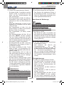
PREPARAZIONE
APPARECCHIO
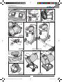
Assemblaggio carrello
(per modelli dotati di carrello smon-
tabile)
- Posizionare a terra il carrello (1 Fig. 1).
- Inserire il maniglione (2 Fig. 1) nel carrel-
lo.
- É possibile regolare il maniglione in altez-
za posizionando e avvitando il pomello di
fermo (3 Fig. 1) in corrispondenza di uno
dei due fori (4 Fig. 1).
- Posizionare il fusto (5 Fig. 2) sul carrello
agganciando il supporto in plastica (6 Fig.
2) al tubo (7 Fig. 2) del carrello.
>>>
Manuale POWER LINE_8050814_1ed_01-2019.indd 1 27/02/19 09:31

www.ghibliwirbel.com
Professional Cleaning Machines Since 1968
ITALIANO -
2
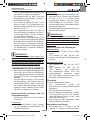
Aspirapolvere
Per apparecchi dotati di adeguati accessori.
- Sganciare le leve (8 Fig. 3) e rimuovere
il coperchio (9 Fig. 4) completo di gruppo
motore ed il portagalleggiante (46 Fig. 4).
- Rimuovere il filtro (10 Fig. 5) in poliestere.
- Controllare, se presente, che all’interno
dell’apparecchio sia montato il sacchetto
in carta (11 Fig. 5).
- Se il sacchetto in carta (11 Fig. 5) non è
presente, montarlo, se necessario, agen-
do come segue:
Calzare il sacchetto in carta (11 Fig. 6)
nella bocchetta (12 Fig. 6) fino a oltrepas-
sare il collare (13 Fig. 6).
- Rimontare il filtro (10 Fig. 5) in poliestere.
- Rimontare il portagalleggiante (46 Fig.
35), con la freccia “FRONT” allineata alla
parte anteriore della macchina (58 Fig.
35); rimontare anche il coperchio (9 Fig.
35) e bloccarlo tramite le leve (8 Fig.3).
- Introdurre, fino a finecorsa, il manicotto
(14 Fig. 7) del tubo di aspirazione nella
bocchetta (15 Fig. 7) presente sul fusto.
- Per sganciare il manicotto (14 Fig. 7)
spostare la levetta (16 Fig. 7) in senso
orario quindi tirare verso l’esterno il ma-
nicotto (14 Fig. 7).
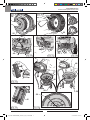
- Unire all’impugnatura ergonomica (17
Fig. 8) o al tubo flessibile (18 Fig. 8) a
seconda dei modelli, la prolunga (19 Fig.
8).
- Unire le due prolunghe rigide (19-20 Fig.
9) facendo coincidere i due riferimenti
(21-22 Fig. 9).
- Unire alla prolunga rigida (20 Fig. 10)
l’accessorio voluto (bocchetta di aspira-
zione, spazzola a pennello, bocchetta a
lancia, bocchetta pavimenti ecc..).
NOTA:
Per modelli dotati di impugnatura ergonomi-
ca è possibile regolare la forza di aspirazione
agendo sul selettore (23 Fig. 11).
Aprendo la nestrella (24 Fig. 11) si ha una
minore azione aspirante.
Collegamento elettrospazzola
Per apparecchi dotati di presa:
- Collegare la spina dell’elettrospazzola
alla presa (25 Fig. 12) presente sulla te-
stata dell’aspirapolvere (massima poten-
za consentita 200 W).
Collegamento utensili
NOTA:
Per questi tipi di macchine viene fornito in
dotazione un apposito tubo con adeguati at-
tacchi per gli utensili.
Collegamento elettroutensile
Per apparecchi dotati di relativa presa.
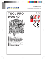
- Sollevare il coperchio (47 Fig. 13) e col-
legare la spina dell’elettroutensile alla
presa (48 Fig. 13) presente sulla testata
dell’aspiratore (massima potenza con-
sentita 2000 W).
Collegamento utensile pneumatico
Per apparecchi dotati di relativi attacchi.
- Collegare il tubo (49 Fig. 13) dell’utensile
pneumatico al relativo raccordo (50 Fig.
13) presente sulla testata dell’aspiratore.
- Collegare la linea di alimentazione pneu-
matica (51 Fig. 13) al raccordo (52 Fig.
13) presente sulla testata dell’aspiratore
(massima pressione consentita 10 bar).
Aspiraliquidi
Per apparecchi dotati di adeguati accessori.
- Sganciare le leve (8 Fig. 3) e rimuovere
il coperchio (9 Fig. 4) completo di gruppo
motore ed il portagalleggiante (46 Fig. 4).
- Rimuovere il filtro (10 Fig. 5) in poliestere
se presente.
- Rimuovere il sacchetto in carta (11 Fig. 5)
se presente.
- Rimontare il portagalleggiante (46 Fig.
35), con la freccia “FRONT” allineata alla
parte anteriore della macchina (58 Fig.
35); rimontare anche il coperchio (9 Fig.
35) e bloccarlo tramite le leve (8 Fig.3).
- Introdurre, fino a finecorsa, il manicotto
(14 Fig. 7) del tubo di aspirazione nella
bocchetta (15 Fig. 7) presente sul fusto.
- Per sganciare il manicotto (14 Fig. 7)
Manuale POWER LINE_8050814_1ed_01-2019.indd 2 27/02/19 09:31

www.ghibliwirbel.com
Professional Cleaning Machines Since 1968
ITALIANO -
3
spostare la levetta (16 Fig. 7) in senso
orario quindi tirare verso l’esterno il ma-
nicotto (14 Fig. 7).
- Unire all’impugnatura ergonomica (17
Fig. 8) o al tubo flessibile (18 Fig. 8), a
seconda dei modelli, la prolunga (19 Fig.
8).
- Unire le due prolunghe rigide (19-20 Fig.
9) facendo coincidere i due riferimenti
(21-22 Fig. 9).
- Unire alla prolunga rigida (20 Fig. 10)
l’accessorio voluto (bocchetta di aspira-
zione, bocchetta pavimenti ecc...
NOTA:
Per modelli dotati di impugnatura ergonomi-
ca è possibile regolare la forza di aspirazione
agendo sulla ghiera (23 Fig. 11).
Aprendo la nestrella (24 Fig. 11) si ha una
minore azione aspirante.
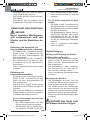
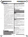
USO DELL’APPARECCHIO
- L’apparecchio è dotato di ruote e quindi
può essere spostato tramite le apposite
maniglie, oppure spinto tramite il mani-
glione (26 Fig. 14).
- Per il suo sollevamento inserire le dita
della mano nell’apposita maniglia (27
Fig. 15) ricavata sulla parte superiore del
coperchio per la versione motore singolo
oppure in due persone tramite le maniglie
(28 Fig. 14).
Avviamento dell’apparecchio come
aspirapolvere o aspiraliquidi
- Inserire la spina (29 Fig. 16) nella presa
di corrente.
Motore singolo
- Premere l’interruttore (30 Fig. 17) su “I”
per avviare il motore di aspirazione, l’in-
terruttore si illumina.
Doppio motore
- A seconda della potenza richiesta è pos-
sibile avviare un solo motore premendo
l’interruttore (31 Fig. 17) su “I” oppure en-
trambe gli interruttori (31 e 32 Fig. 17) se
è richiesta una maggiore forza aspirante.
Con interruttore premuto il relativo pul-
sante si illumina.
NOTA:
Quando il serbatoio di recupero è pieno, si
ha un aumento di rumore e l’apparecchio
non aspira più, quindi spegnere l’apparec-
chio e svuotare il serbatoio come descritto
nei relativi paragrafi.
Avviamento apparecchio con utensili
Avviamento manuale
- Posizionare l’interruttore (57 Fig. 18) su
“MAN”
- Premere l’interruttore (53 Fig. 18) su
“ON” che si illumina; l’aspiratore si avvia.
Avviamento automatico
- Posizionare l’interruttore (57 Fig. 18) su
“AUT”
- Premere l’interruttore (53 Fig. 18) su
“ON” che si illumina. L’aspiratore si avvia
quando si avvia l’utensile collegato, e si
ferma pochi secondi dopo lo spegnimen-
to dell’utensile.
Scuotifiltro
Per macchine dotate.
- Rimuovere il tubo di aspirazione come
descritto nel relativo paragrafo.
- Avviare il motore di aspirazione.
- Con una mano tappare la bocchetta
di aspirazione (15 Fig. 19) e con l’altra
mano aprire lo sportello (54 Fig. 19) per
uno - due secondi.
- Ripetere la procedure per 3 volte, quindi
spegnere il motore di aspirazione.
Spegnimento dell’apparecchio
- Premere gli interruttori (30, 31, 32 Fig.
17) su “0” per spegnere l’apparecchio; le
lampade, se presenti sugli interruttori, si
spengono.
- Staccare la spina (29 Fig. 16) dalla presa
di corrente.
- Avvolgere il cavo (33 Fig.20) e aggan-
ciarlo nell’apposita sede (34 Fig. 20).
Manuale POWER LINE_8050814_1ed_01-2019.indd 3 27/02/19 09:31

www.ghibliwirbel.com
Professional Cleaning Machines Since 1968
ITALIANO -
4
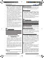
PULIZIA E MANUTENZIONE
PERICOLO:
Prima di effettuare qualsiasi
operazione di manutenzione ri-
muovere la spina dalla presa di
corrente.
Rimozione e sostituzione sacchetto
raccogli polvere in carta (se presente)
- Sganciare le leve (8 Fig. 3) e rimuovere
il coperchio (9 Fig. 4) completo di gruppo
motore e portagalleggiante (46 Fig. 4).
- Rimuovere il filtro (10 Fig. 5) in poliestere.
- Togliere il sacchetto in carta raccogli pol-
vere (11 Fig. 5), e sostituirlo come indica-
to in precedenza.
- Rimontare il tutto procedendo in senso
inverso allo smontaggio.
Svuotamento serbatoio di recupero
- Sganciare le leve (8 Fig. 3) e rimuovere
il coperchio (9 Fig. 4) completo di gruppo
motore e portagalleggiante (46 Fig. 4).
- Posizionarsi su una piletta di scarico e
svuotare il liquido contenuto nel serbatoio
di recupero (35 Fig. 21).
- Pulire l’interno del serbatoio con acqua
corrente quindi rimontare il tutto proce-
dendo in senso inverso allo smontaggio.
Per apparecchi dotati di tubo di scari-
co
- Sganciare il tubo di scarico (36 Fig.
22) da relativo supporto.
- Svitare il pomello (37 Fig. 23), rimuo-
vere il tappo (38 Fig. 23) del tubo di
scarico (36 Fig. 24) e svuotare il liqui-
do contenuto nel serbatoio di recupe-
ro (35 Fig. 24).
Per apparecchi dotati di fusto bascu-
lante
- Sganciare le leve (8 Fig. 3) e rimuo-
vere il coperchio (9 Fig. 4) completo
di gruppo motore e portagalleggiante
(46 Fig. 4).
- Sganciare il fermo serbatoio agendo
sulla leva (39 Fig. 25) se presente.
- Sollevare il serbatoio (35 Fig. 26) tra-
mite l’apposita maniglia (40 Fig. 26)
fino al completo svuotamento.
- Rimontare il tutto procedendo in sen-
so inverso allo smontaggio.
Pulizia gionaliera
Controllo e pulizia filtro in poliestere
(se presente)
- Sganciare le leve (8 Fig. 3) e rimuovere
il coperchio (9 Fig. 4) completo di gruppo
motore e portagalleggiante (46 Fig. 4).
- Rimuovere il filtro (11 Fig. 5) in poliestere.
- Pulire il filtro (Fig. 27) dall’interno verso
l’esterno con un getto d’aria.
- Rimontare il tutto procedendo in senso
inverso allo smontaggio.
Pulizia apparecchio
- Pulire il corpo apparecchio utilizzando un
panno umido d’acqua o detergente neu-
tro.
- Rimuovere la testata come indicato in
precedenza e pulire l’interno del serba-
toio con acqua corrente quindi svuotarlo
come indicato precedentemente.
Rimontare il tutto procedendo in senso
inverso allo smontaggio.
PERICOLO:
Non lavare l’apparecchio con
getti d’acqua.
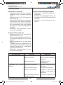
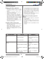
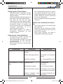
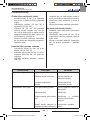
PROBLEMA CAUSA RIMEDIO
Aspiratore non funziona. Interruttore non premuto.
Spina non inserita.
Mancanza corrente.
Premere l’interruttore.
Inserire la spina nella presa
di corrente.
Verificare la linea di
alimentazione.
L’aspirazione non è soddi-
sfacente.
Sacchetto in carta pieno.
Elementi filtranti intasati.
Accessori o tubi otturati.
Racla bocchetta aspirazione
usurata o rovinata.
Sostituire il sacchetto racco-
gli polvere.
Pulire gli elementi filtranti.
Controllare e pulire il tubo
flessibile e la bocchetta di
aspirazione.
Controllare e sostituire la ra-
cla.
Manuale POWER LINE_8050814_1ed_01-2019.indd 4 27/02/19 09:31

www.ghibliwirbel.com
Professional Cleaning Machines Since 1968
ITALIANO -
5
Controlli periodici
Pulizia filtro a cartuccia
- Sganciare le leve (8 Fig. 3) e rimuovere
il coperchio (9 Fig. 4) completo di gruppo
motore.
- Svitare il pomello (55 Fig. 28) e togliere il
filtro (56 Fig. 28).
- Pulire il filtro (56 Fig. 29) con un getto d’a-
ria dall’interno verso l’esterno; è possibile
lavare il filtro (56 Fig. 29) in acqua tiepi-
da e rimontarlo solo dopo una completa
asciugatura, se si presenta troppo sporco
sostituirlo.
- Rimontare il tutto procedendo in senso
inverso allo smontaggio.
Controllo filtro uscita aria
- Svitare le viti (41 Fig. 30) e rimuovere il
coperchietto (42 Fig. 30).
- Rimuovere la spugnetta filtro (43 Fig. 31)
e le spugnette bugnate (44 Fig. 32) se
presenti.
- Pulire le spugnette con un getto d’aria
(Fig. 33).
È possibile lavare le spugnette filtro in
acqua tiepida e rimontarle solo dopo una
completa asciugatura; se si presentano
troppo sporche sostituirle.
- Rimontare il tutto procedendo in senso
inverso allo smontaggio.
Controllo funzionalità galleggiante
- Rimuovere la testata come indicato in
precedenza.
- Verificare che il galleggiante (45 Fig. 34)
sia integro e che scorra liberamente nella
sua sede.
- Rimontare il tutto procedendo in senso
inverso.
PROBLEMA CAUSA RIMEDIO
Aspiratore non funziona. Interruttore non premuto.
Spina non inserita.
Mancanza corrente.
Premere l’interruttore.
Inserire la spina nella presa
di corrente.
Verificare la linea di
alimentazione.
L’aspirazione non è soddi-
sfacente.
Sacchetto in carta pieno.
Elementi filtranti intasati.
Accessori o tubi otturati.
Racla bocchetta aspirazione
usurata o rovinata.
Sostituire il sacchetto racco-
gli polvere.
Pulire gli elementi filtranti.
Controllare e pulire il tubo
flessibile e la bocchetta di
aspirazione.
Controllare e sostituire la ra-
cla.
Manuale POWER LINE_8050814_1ed_01-2019.indd 5 27/02/19 09:31

www.ghibliwirbel.com
Professional Cleaning Machines Since 1968
Manuale POWER LINE_8050814_1ed_01-2019.indd 6 27/02/19 09:31

www.ghibliwirbel.com
Professional Cleaning Machines Since 1968
ENGLISH -
1
INTRODUCTION
DANGER:
Before using the machine,
carefully read the “SAFETY
RECOMMENDATIONS FOR
VACUUM CLEANERS” booklet
attached to this document.
TYPE OF USE
These devices were designed to vacuum liq-
uids or solids or both, according to the tech-
nical data table from the introduction to this
manual. They were designed only for this
use.
DANGER:
The manufacturer can not be
held responsible for any dam-
age due to improper or incor-
rect use.
Any other use releases the
manufacturer from liability for
harm to persons and/or proper-
ty and invalidates any warranty
condition.
WARNING:
Do not use the unit for:
- Vacuum hot substances.
- Don’t pick up flammable, incan-
descent, explosive or toxic dust/
blends.
- This machine is not suitable for
picking up dangerous dust.
- Do not use the equipment in
hazardous environments.
- Do not use the appliance in
liquid suction mode to suction
powder and vice versa.
Users must be properly trained
to use the machine.
WARNING:
Do not use outdoors.
This appliance must be stored,
taking its weight into considera-
tion, on a solid, steady, safe and
not sloping plane, indoor and in
a dry area.
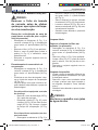
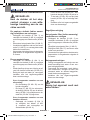
PREPARING
THE APPLIANCE
Trolley installation
(for models equipped with detach-
able trolley)
- Place the trolley on the ground (1 Fig. 1).
- Insert the handle (2 Fig. 1) in the trolley.
- It Is possible to adjust the handle’s height,
positioning it and tightening the fixing but-
ton (3 Fig. 1) in one of the two positions (
4 Fig.1 ).
- Place the cover (5 Fig. 2) on the trolley,
setting the support In the plastic (6 Fig. 2)
on the trolley’s rod (7 Fig. 2).
>>>
Manuale POWER LINE_8050814_1ed_01-2019.indd 1 27/02/19 09:31

www.ghibliwirbel.com
Professional Cleaning Machines Since 1968
ENGLISH -
2
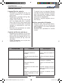
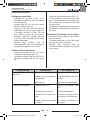
Vacuum cleaner
For appliances equipped with suitable acces-
sories.
- Release the levers (8 Fig. 3) and remove
the cover (9 Fig. 4) complete with the mo-
tor unit and floater-holder (46 Fig. 4).
- Remove the polyester filter (10 Fig. 5).
- Check, if applicable, that inside the de-
vice to be set the paper bag (11 Fig. 5).
- If the paper bag (11 Fig. 5) is not there,
install it, if necessary, acting as follows:
Install the paper bag (11 Fig. 6) in the
nozzle (12 Fig. 6) until it passes the band-
ing (13 Fig. 6).
-
Reassemble the polyester filter
(10 Fig.
5).
- Re-mount the floater-holder (46 Fig. 35),
with the “FRONT” arrow aligned with the
front part of the machine (58 Fig. 35);
also re-mount the cover (9 Fig. 35) and
block it via the levers (8 Fig.3).
- Insert, as far as possible, the sleeve (14
Fig. 7) of the suction hose into the nozzle
(15 Fig. 7) on the drum.
- To release the sleeve (14 Fig. 7) turn the
lever (16 Fig. 7) clockwise and then pull
the sleeve outwards (14 Fig. 7).
- Connect the ergonomic handle (17 Fig. 8)
or the hose (18 Fig. 8) depending on the
model, with the extension (19 Fig. 8).
- Connect the two rigid extensions (19-
20 Fig. 9) by aligning the two reference
points (21-22 Fig. 9).
- Attach to the rigid extension (20 Fig. 10)
the desired accessory ( the vacuum noz-
zle, the dust brush, the accessory for tight
spaces, the floor nozzle etc..
NOTES:
For models equipped with ergonomic handle
is possible to adjust the suction force, by act-
ing the selector (23 Fig. 11).
By opening the window (24 Fig. 11) you get a
lower suction force.
Connecting the electrical brush
For devices with socket:
- Connect the electrical brush’s plug to the
socket (25 Fig. 12) located on the top of
the vacuum (maximum output 200 W).
Tools connection
NOTE:
A relevant hose is supplied for these types of
machine, with suitable tool attachments.
Power tool connection
For appliances fitted with relative outlet.
- Lift the cover (47 Fig. 13) and connect
the power tool plug to the outlet (48 Fig.
13) present on the head of the vacuum
cleaner (maximum power allowed 2000
W).
Pneumatic tool connection
For appliances fitted with relative
attachments.
- Connect the hose (49 Fig. 13) of the
pneumatic tool to the relative fitting
(50 Fig. 13) present on the head of the
vacuum cleaner.
- Connect the pneumatic power supply
line (51 Fig. 13) to the fitting (52 Fig.
13) present on the head of the vacuum
cleaner (maximum pressure allowed 10
bar).
Liquid suction
For appliances equipped with suitable acces-
sories.
- Release the levers (8 Fig. 3) and remove
the cover (9 Fig. 4) complete with the mo-
tor unit and floater-holder (46 Fig. 4).
- Remove the polyester filter (10 Fig. 5) if
present.
- Remove the paper bag (11 Fig. 5) if pre-
sent.
- Re-mount the floater-holder (46 Fig. 35),
with the “FRONT” arrow aligned with the
front part of the machine (58 Fig. 35);
also re-mount the cover (9 Fig. 35) and
block it via the levers (8 Fig.3).
- Insert, as far as possible, the sleeve (14
Fig. 7) of the suction hose into the nozzle
Manuale POWER LINE_8050814_1ed_01-2019.indd 2 27/02/19 09:31

www.ghibliwirbel.com
Professional Cleaning Machines Since 1968
ENGLISH -
3
(15 Fig. 7) on the drum.
- To release the sleeve (14 Fig. 7) turn the
lever (16 Fig. 7) clockwise and then pull
the sleeve outwards (14 Fig. 7).
- Merge the ergonomic handle (17 Fig.
8) or hose (18 Fig. 8) depending on the
model, with the extension (19 Fig. 8).
- Connect the two rigid extensions (19-
20 Fig. 9) by aligning the two reference
points (21-22 Fig. 9).
- Mount on the rigid extension (20 Fig. 10)
the desired accessory,( vacuum nozzle,
floor nozzle etc..)
NOTES:
For models equipped with ergonomic handle
it is possible to adjust the suction force acting
the nut (23 Fig. 11).
By opening the little window (24 Fig. 11) you
get a lower suction force.
USING THE APPLICANCE
- The device is equipped with wheels and
thus can be moved with the proper han-
dles, or it can be pushed with the help of
the handle (26 Fig. 14).
- To lift it up insert your fingers under the
dedicated handle (27 Fig. 15) on the top
of the cover of the single version motor or
lift with the help of two people using the
handles (28 Fig. 14).
Starting the appliance as a dust
suction device or liquid suction
device
- Insert the plug (29 Fig.16) into the socket.
Single motor
- Push the switch (30 Fig. 17) on “I” to start
the suction motor; the switch lights up.
Double motor
- Depending on the power required it is
possible to start only one motor by press-
ing the switch (31 Fig. 17) on “I” or both
switches (31 e 32 Fig. 17) if a greater
suction force is required.
When the switch pressed the correspond-
ing button lights up.
NOTES:
When the recovery tank is full, the noise
intensity increases and the device can no
longer aspire. Then you must switch off the
device and empty the tank as described in
the relevant paragraphs.
Starting the appliance with tools
Manual start-up
- Position the switch (57 Fig. 18) at “MAN”
- Press the switch (53 Fig. 18) at “ON”,
which lights up; the vacuum cleaner
starts.
Automatic start-up
- Position the switch (57 Fig. 18) at “AUT”
- Press the switch (53 Fig. 18) at “ON”,
which lights up. The vacuum cleaner
starts-up when the tool connected starts
and stops a few seconds after tool switch-
off.
Filter-shaker
For machines supplied.
- Remove the suction hose as described in
the relative paragraph.
- Start the suction motor.
- Use one hand to block the suction nozzle
(15 Fig. 19) and use the other hand to
open the hatch (54 Fig. 19) for one - two
seconds.
- Repeat the procedure 3 times and then
switch the suction motor off.
Switching off the appliance
- Push the switches (30, 31, 32 Fig. 17)
to the “0” position to stop the device; the
lights, if any on the switches, will go off.
- Remove the plug (29 Fig. 16) from the
electrical socket.
- Wind up the cable (33 Fig. 20) and hook
it onto its housing (34 Fig. 20).
Manuale POWER LINE_8050814_1ed_01-2019.indd 3 27/02/19 09:31

www.ghibliwirbel.com
Professional Cleaning Machines Since 1968
ENGLISH -
4
CLEANING AND
MAINTENANCE
DANGER:
Before performing any main-
tenance operation, unplug the
appliance from the electrical
socket.
Removing and replacing the paper
dust collection bag (if present)
- Release the levers (8 Fig. 3) and remove
the cover (9 Fig. 4) complete with motor
unit and floater-holder (46 Fig. 4).
- Remove the polyester filter (10 Fig. 5).
- Remove the paper bag for collecting dust
(11 Fig. 5), and replace it as described
above.
- Reassemble all the parts by following the
dismantling process steps in the reverse
order.
Emptying the recovery tank
- Release the levers (8 Fig. 3) and remove
the cover (9 Fig. 4) complete with motor
unit and floater-holder (46 Fig. 4).
- Place it on the top of a drain and empty
the liquid in the recovery tank (35 Fig.
21).
- Clean the inside of the tank with running
water and then re-install everything doing
the opposite of the disassembly.
For machines equipped with drain
hose
- Release the exhaust tube (36 Fig. 22)
from its base.
- Unscrew the button (37 Fig. 23), re-
move the cap (38 Fig. 23) of the ex-
haust hose (36 Fig. 24) and drain the
liquid in the recovery tank (35 Fig.
24).
For devices with rocking tank
- Release the levers (8 Fig. 3) and re-
move the cover (9 Fig. 4) complete
with motor unit and floater-holder (46
Fig. 4).
- Remove the tank locking device by
acting the lever (39 Fig. 25) if any
- Lift the tank (35 Fig. 26) with the ap-
propriate lever (40 Fig. 26) until com-
pletely emptied.
- Replace everything doing the oppo-
site of the disassembly.
Daily cleaning
Checking and cleaning the polyester
filter (if present)
- Release the levers (8 Fig. 3) and remove
the cover (9 Fig. 4) complete with motor
unit and floater-holder (46 Fig. 4).
- Remove the polyester (11 Fig. 5) filter.
- Clean the filter (Fig. 27) from the inside
out with a blast of air.
- Reassemble all the parts by following the
dismantling process steps in the reverse
order.
Cleaning the appliance
- Clean the unit body with a cloth damp-
ened with water or a mild detergent.
- Remove the top, as described above and
clean the inside with running water and
then empty it, as indicated above.
Replace everything doing the opposite of
the disassembly.
DANGER:
Do not wash the appliance us-
ing jets of water.
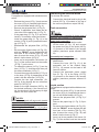
PROBLEM CAUSE SOLUTION
The vacuum cleaner does
not work.
Switch not pressed.
Plug not inserted.
No current.
Press the switch.
Insert the plug into the sock-
et.
Check the power supply line.
Suction is not satisfactory. Paper bag full.
Filter elements clogged.
Accessories or tubes
clogged.
Suction nozzle squeegee
worn or damaged.
Replace the dust bag.
Clean the filter elements.
Check and clean the flexible
hose and the suction nozzle.
Check and replace the
squeegee.
Manuale POWER LINE_8050814_1ed_01-2019.indd 4 27/02/19 09:31
La pagina si sta caricando...
La pagina si sta caricando...
La pagina si sta caricando...
La pagina si sta caricando...
La pagina si sta caricando...
La pagina si sta caricando...
La pagina si sta caricando...
La pagina si sta caricando...
La pagina si sta caricando...
La pagina si sta caricando...
La pagina si sta caricando...
La pagina si sta caricando...
La pagina si sta caricando...
La pagina si sta caricando...
La pagina si sta caricando...
La pagina si sta caricando...
La pagina si sta caricando...
La pagina si sta caricando...
La pagina si sta caricando...
La pagina si sta caricando...
La pagina si sta caricando...
La pagina si sta caricando...
La pagina si sta caricando...
La pagina si sta caricando...
La pagina si sta caricando...
La pagina si sta caricando...
La pagina si sta caricando...
La pagina si sta caricando...
La pagina si sta caricando...
La pagina si sta caricando...
La pagina si sta caricando...
La pagina si sta caricando...
La pagina si sta caricando...
La pagina si sta caricando...
La pagina si sta caricando...
La pagina si sta caricando...
La pagina si sta caricando...
La pagina si sta caricando...
La pagina si sta caricando...
La pagina si sta caricando...
La pagina si sta caricando...
La pagina si sta caricando...
La pagina si sta caricando...
La pagina si sta caricando...
La pagina si sta caricando...
La pagina si sta caricando...
La pagina si sta caricando...
La pagina si sta caricando...
La pagina si sta caricando...
La pagina si sta caricando...
La pagina si sta caricando...
La pagina si sta caricando...
-
 1
1
-
 2
2
-
 3
3
-
 4
4
-
 5
5
-
 6
6
-
 7
7
-
 8
8
-
 9
9
-
 10
10
-
 11
11
-
 12
12
-
 13
13
-
 14
14
-
 15
15
-
 16
16
-
 17
17
-
 18
18
-
 19
19
-
 20
20
-
 21
21
-
 22
22
-
 23
23
-
 24
24
-
 25
25
-
 26
26
-
 27
27
-
 28
28
-
 29
29
-
 30
30
-
 31
31
-
 32
32
-
 33
33
-
 34
34
-
 35
35
-
 36
36
-
 37
37
-
 38
38
-
 39
39
-
 40
40
-
 41
41
-
 42
42
-
 43
43
-
 44
44
-
 45
45
-
 46
46
-
 47
47
-
 48
48
-
 49
49
-
 50
50
-
 51
51
-
 52
52
-
 53
53
-
 54
54
-
 55
55
-
 56
56
-
 57
57
-
 58
58
-
 59
59
-
 60
60
-
 61
61
-
 62
62
-
 63
63
-
 64
64
-
 65
65
-
 66
66
-
 67
67
-
 68
68
-
 69
69
-
 70
70
-
 71
71
-
 72
72


Ghibli & Wirbel POWER TOOL PRO FD 50 P EL Use And Maintenance
- Categoria
- Aspirapolvere
- Tipo
- Use And Maintenance
in altre lingue
- français: Ghibli & Wirbel POWER TOOL PRO FD 50 P EL
- español: Ghibli & Wirbel POWER TOOL PRO FD 50 P EL
- Nederlands: Ghibli & Wirbel POWER TOOL PRO FD 50 P EL
- português: Ghibli & Wirbel POWER TOOL PRO FD 50 P EL
Documenti correlati
-
 Ghibli & Wirbel POWER D 22 I Use And Maintenance
-
 Ghibli & Wirbel POWER D 12 HE Use And Maintenance
-
 Ghibli & Wirbel POWER EXTRA 7 I Auto Use And Maintenance
-
 Ghibli & Wirbel TOOL PRO WDA 40 L AS Use And Maintenance
-
 Ghibli & Wirbel InPump 90.2 SP CF Use And Maintenance
-
 Ghibli & Wirbel M 26 I ULKA Use And Maintenance
-
 Ghibli & Wirbel S-Team 6 V Use And Maintenance
-
 Ghibli & Wirbel AS 2 Use And Maintenance
-
 Ghibli & Wirbel O 143 U 10 Use And Maintenance
-
 Ghibli & Wirbel T1 FLY Use And Maintenance


