
OPERATING INSTRUCTIONS
WIRELESS TRANSMITTER WM-5325
Thank you for purchasing TOA's Wireless Transmitter.
Please carefully follow the instructions in this manual to ensure long, trouble-free use of your equipment.
TABLE OF CONTENTS
página 36
página 48
! ၁
Español:
Português:
ᇖ ฿ሺ
:
English:
Deutsch:
Français:
page
seite
page
1
12
24
1. SAFETY PRECAUTIONS ............................................................................... 2
2. GENERAL DESCRIPTION ............................................................................. 3
3. FEATURES ......................................................................................................... 3
4. HANDLING PRECAUTIONS ......................................................................... 3
5. NOMENCLATURE ............................................................................................ 4
6. BATTERY INSERTION .................................................................................... 6
7. WHEN OPERATING ON RECHARGEABLE BATTERY ...................... 7
8. CHANNEL NUMBER SETTING ................................................................... 8
9. OPERATION ....................................................................................................... 8
10. OPERATIONAL HINTS ................................................................................... 9
11. DISTANCE BETWEEN THE MICROPHONE AND THE MOUTH ...... 9
12. AUDIO LEVEL ADJUSTMENT (SENSITIVITY CONTROL) ................ 9
13. SPECIFICATIONS .......................................................................................... 10

2
When the Unit is in Use
• To prevent the electromagnetic wave from badly
influencing medical equipment, make sure to
switch off the unit's power when placing it in close
proximity to the medical equipment.
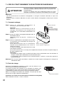
• Use TOA's BC-5000 Battery Charger when
recharging.
• The wireless transmitter can be powered by WB-
2000 Battery. But, if use of any other than the
counter specified battery into the BC-5000 Battery
Charger, it may cause fire, personal injury, or
environmental contamination due to battery rupture
or leakage.
• The use of any other than the specified charger
could result in fire, personal injury, or
environmental contamination due to battery rupture
or leakage.
• Stop charging, if the batteries are not fully charged
within 3 hours. Failure to do so may cause the
batteries to fire, explode, leak, or heat.
• Never short-circuit the charging terminals on the
bottom of the transmitter with metal objects. Doing
so could result in electric shocks or burns.
When the Unit is in Use
• When the unit is not in use for 10 days or more, be
sure to take the battery out of the unit because
battery leakage may cause personal injury or
contamination of environment.
• Make sure to observe the following handling
precautions so that a fire or personal injury does
not result from leakage or explosion of the battery.
· Do not short, disassemble, heat nor put the
battery into a fire.
· Never charge batteries of the type which are not
rechargeable.
· Do not solder a battery directly.
· Be sure to use the specified type of battery.
· Note correct polarity (positive and negative
orientation) when inserting a battery in the unit.
· Avoid locations exposed to the direct sunlight,
high temperature and high humidity when storing
batteries.
Do not place the dry cell battery into charger.
Placing non-rechargeable batteries in the charger
may cause the battery to crack resulting in a fire
and/or harm to the body.
When recharging, please only use the BC-5000
Battery Charger and WB-2000 Battery.
Do not use other battery types.
When the battery becomes inflated or leaks,
discontinue use and replace with new one
immediately.
If there’s any burning and/or peculiar smell while
charging the battery, please switch off the power
immediately.
The frequencies between 865 MHz and 867 MHz do
not comply with "CE."
CAUTION TO USER: Changes or modifications not
expressly approved by the party responsible for
compliance could void the user's authority to operate
the equipment.
IMPORTANT NOTE: To comply with the FCC RF
exposure compliance requirements, no change to
the antenna or the device is permitted. Any change
to the antenna or the device could result in the
device exceeding the RF exposure requirements and
void user’s authority to operate the device.
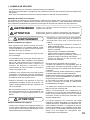
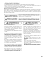
1. SAFETY PRECAUTIONS
• Be sure to read the instructions in this section carefully before use.
• Make sure to observe the instructions in this manual as the conventions of safety symbols and messages
regarded as very important precautions are included.
• We also recommend you keep this instruction manual handy for future reference.
Safety Symbol and Message Conventions
Safety symbols and messages described below are used in this manual to prevent bodily injury and property
damage which could result from mishandling. Before operating your product, read this manual first and
understand the safety symbols and messages so you are thoroughly aware of the potential safety hazards.
WARNING
CAUTION
Indicates a potentially hazardous situation which, if mishandled, could
result in death or serious personal injury.
Indicates a potentially hazardous situation which, if mishandled, could
result in moderate or minor personal injury, and/or property damage.
WARNING
CAUTION

3
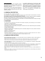
2. GENERAL DESCRIPTION
The TOA's WM-5325 is a wireless transmitter.
The YP-M5300 and YP-M5310 are lavalier microphones and the WH-4000A and WH-4000H are headset
microphones; they are all optional and designed for speech use.
The YP-M5310 employs an omnidirectional electret condenser microphone element, while the YP-M5300,
WH-4000A and WH-4000H employ unidirectional electret condenser microphone elements.
The difference between the WH-4000A and the WH-4000H is that the WH-4000A features sweat-proof design
and is supplied with an optional waist pouch.
3. FEATURES
• An optimized PLL-synthesizer minimizes the oscillation frequency drift resulting from the ambient
temperature or voltage fluctuation.
• Audio level control adjusts the microphone sensitivity.
• Power/Battery lamps indicate battery consumption to prevent the unit from malfunctioning when the battery
level remarkably decreases.
• Compact and high reliability
• Sweat-proof headset with an adjustable fixing band is exclusively designed for use by aerobics instructors.
(Usable with WH-4000A)
• Operates on a single AA battery.
• Employs a built-in antenna.
• The state of battery consumption can be displayed on the tuner's indicator when the unit is used in
conjunction with the optional WT-5800, WT-5805 or WT-5810 Wireless Tuner.
4. HANDLING PRECAUTIONS
• Do not expose the unit to rain or an environment where it may be splashed by water or other liquids, as
doing so may result in unit failure.
• Never open nor remove the unit case to modify the unit. Refer all servicing to your nearest TOA dealer.
• Take care not to drop the unit onto the floor nor bump it against a hard object as the unit could fail.
• Do not place the unit in locations of high temperature (ex. in an ill-ventilated car in summer) or high humidity
as the unit could fail.
• Do not use the unit in locations where it is exposed to seawater.
• To clean, use a dry cloth. When the unit gets very dirty, wipe lightly with a cloth damped in a dilute neutral
cleanser, then wipe with a dry cloth. Never use benzine, thinner, or chemically-treated cleaning towel.
• Avoid using a mobile telephone near the unit in use. Noise could be picked up.
• When using two or more units, keep them at least 50 cm away from each other to avoid malfunctions or
noise.
• Keep the unit at least 3 m away from the receiving antenna. Using the unit in close proximity to the antenna
could result in malfunctions or noise.
License requirement
The term "IC:" before the radio certification number
only signifies that Industry Canada Technical
specifications were met. Operation is subject to the
following two conditions;
(1) This device may not cause harmful interference,
and (2) this device must accept any interference
received, including interference that may cause
undesired operation.
Le présent appareil est conforme aux CNR
d'Industrie Canada applicables aux appareils radio
exempts de licence. L'exploitation est autorisée aux
deux conditions suivantes : (1) l'appareil ne doit pas
produire de brouillage, et (2) l'utilisateur de l'appareil
doit accepter tout brouillage radioélectrique subi,
même si le brouillage est susceptible d'en
compromettre le fonctionnement.

4
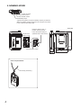
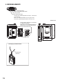
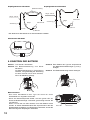
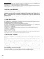
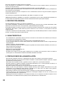
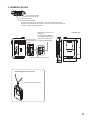
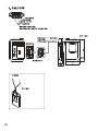
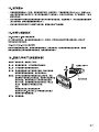
Neck strap attachment
Neck strap (accessory)
Unit: mm
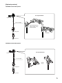
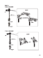
5. NOMENCLATURE
Inside of the
battery cover
Channel setting switch
Keep the switch in the "L"
position (factory-preset).
Leave the switch setting to
qualified service technicians.
Audio level control
Power ON/OFF switch
Power/Battery lamps
19
23
62
98
Clip
A green LED lights as long as the battery capacity is sufficient.
When the battery capacity becomes low, the green LED starts
to dim, while the red LED to light.
Input connector

5
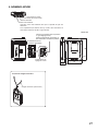
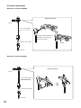
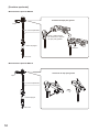
Tie-clip attachment
Clip
Plug lock
ø3.5 mm
1.3 m in length
[Optional products]
YP-M5310 Lavalier Microphone
Clip
1.3 m in length
Tie-clip attachment
Set the Microphone's
narrow portion in the
tie-clip's holder.
Rotatable
Plug lock
ø3.5 mm
YP-M5300 Lavalier Microphone

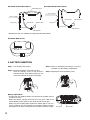
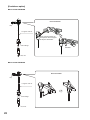
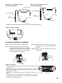
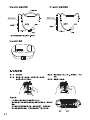
6
Plug lock
ø3.5 mm
Windscreen*
Gooseneck
Adjustable band
Microphone
1.3 m in length
WH-4000A Headset Microphone
Plug lock
ø3.5 mm
Windscreen*
Gooseneck
Microphone
1.3 m in length
WH-4000H Headset Microphone
WH-4000P Waist Pouch
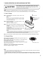
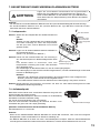
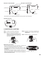
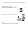
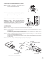
6. BATTERY INSERTION
Step 1. Turn off the power switch.
Step 2. Remove the battery cover from the unit.
Slide the battery cover in the direction
indicated by the arrow while pressing on the
cover with a thumb as shown in the figure.
Step 3. Insert an AA battery according to (+) and (–)
indications on the battery compartment.
Step 4. Replace the removed battery cover.
Battery replacement
• A brand-new AA alkaline battery will continuously operate the unit
for about 10 hours.
• When the battery capacity becomes low, the green LED of the
Power/ Battery lamps starts to dim, while the red LED to light.
When only the red LED lights, replace the battery with a new one.
In this condition, the unit transmits the remaining battery capacity
information to the tuner, causing the tuner's BATT indicator to light.
Red LED
Green LED
* Windscreens are also available as optional product WH-4000S.

7
Notes
• When operating on rechargeable batteries, the optional BC-5000 Battery Charger is required.
• For rechargeable batteries, be sure to use the optional WB-2000 battery. Do not use other batteries.
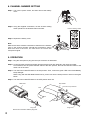
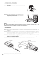
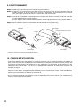
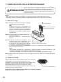
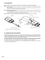
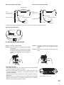
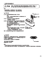
7.1. How to Charge
Step 1. Set the wireless transmitter's power switch to the
OFF position.
Note
Be sure to turn off the transmitter's power switch
when charging. Batteries cannot be correctly charged
if the power switch is ON.
Step 2. Place the WB-2000 rechargeable battery in the
wireless transmitter.
(Refer to p. 6 "Battery insertion.")
Step 3. Fully insert the wireless transmitter into the
transmitter receptacle of the BC-5000 Battery
Charger.
The BC-5000's charging indicator lights red and
charging begins.
Charging is completed in approximately 3 hours and
the BC-5000's full-charge indicator lights green.
Notes
• If the red charging indicator does not light even if the wireless transmitter has been inserted into the
charger, check to see if the transmitter has been correctly inserted.
• The wireless transmitter becomes warm after charging completion, however this is not a failure.
Note: For more information, please read the instruction manual enclosed with the BC-5000 Battery Charger.
7.2. Charging Timing
Please charge the equipment immediately when green LED light is off
and red light is on during use.
When the battery alarm lamp on the receiver is on, the battery level of
the transmitter is low as well.
The transmitter will not be able to operate within a few minutes.
Even though the battery remains enough, both green and red lights
might be on at the same time.
[Guidelines on the rechargeable battery operation time]
Continuous usage time: Approx. 13 hours
7. WHEN OPERATING ON RECHARGEABLE BATTERY
When charging, never insert rechargeable batteries other than the
specified WB-2000 battery in the wireless microphone (transmitter).
Charging any other than the WB-2000 battery may result in fire or
personal injury due to battery rupture.
CAUTION
Notes
• When using the WB-2000 rechargeable battery for the first time or when using it after it has been stored for
a long period of time, be sure to charge it before use.
• The WB-2000 battery is designed to cycle through about 500 charges and discharges. When the transmitter
operation interval becomes extremely short after prolonged repeated use, change the battery with a new
one.
Power/Battery lamps
Power switch
1
Charging indicator (red)
Full-charge indicator (green)
3
Note
Can be placed in either
backward looking or
forward looking
orientation.

8
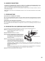
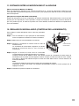
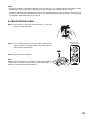
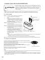
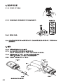
9. OPERATION
Step 1. Plug the microphone's plug into the input connector as illustrated.
Step 2. Confirm that the wireless transmitter and the wireless tuner are identical in the channel number.
If not identical, turn the power ON/OFF switch to the OFF position, then set the channel number to the
same one as the tuner.
Step 3. Turn the Power ON/OFF switch to the ON position. Then, confirm the green LED of the Power/Battery
lamps will light.
When using with the WH-4000P Waist Pouch, put the unit into the waist pouch as shown in the figure
below.
Step 4. Turn the Power ON/OFF switch to the OFF position after use.
Secure the connection with the plug lock.
WM-5325
Hook and loop fastener
Belt
Plug lock
Plug lock
WH-4000P
1
3
Channel setting switch
8. CHANNEL NUMBER SETTING
Step 1. Turn off the power switch, and then remove the battery
cover.
Step 2. Using the supplied screwdriver, set the Channel setting
switch pointers to the desired channel number.
Step 3. Replace the battery cover.
Note
Make sure that the wireless transmitter is identical to the wireless
tuner in the channel number. Should the transmitter's setting
differ from that of the tuner, the tuner does not receive the
microphone signal.

9
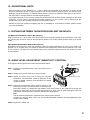
10. OPERATIONAL HINTS
• The transmitter's service distance is 3 – 120 m. When the transmitter user moves in a facility, signal
dropouts (momentary losses of signal reception) may be encountered. These dropouts are caused by the
building's architectural designs or materials which block the travel of or reflect the radio signal. If this occurs,
the user needs to change locations for better signal reception.
• The proper operation of your wireless system may be interfered with by other system operating on the same
frequency. In such cases, change the operating frequency of your system. (As to dealing with the
interference, refer to the operating instructions of the wireless tuner.)
• Should you have any questions regarding the use or availability of TOA wireless products, please contact
your local TOA dealer.
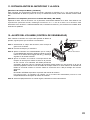
11. DISTANCE BETWEEN THE MICROPHONE AND THE MOUTH
[YP-M5300 and YP-M5310 Lavalier Microphones]
Keep your mouth 15 – 20 cm away from the microphone for the best possible sound reproduction. Take care
not to bring your mouth too close to the microphone (within 5 cm) as this impairs speech clarity if you speak
loudly.
[WH-4000A and WH-4000H Headset Microphones]
By adjusting the gooseneck, locate the microphone with the supplied windscreen in front of your mouth, and
position it 3 – 5 cm away from your mouth for the best sound reproduction. When the microphone is too close
to your mouth or you speak too loud, speech clarity will be impaired, making it hard for the audience to hear
announcements.
12. AUDIO LEVEL ADJUSTMENT (SENSITIVITY CONTROL)
To change the factory-preset level, follow the procedures below.
Step 1. Holding the transmitter body, open the rubber cap as
illustrated.
Step 2. Switch on the power of the tuner and transmitter.
Step 3. Adjust the audio level control using the supplied
screwdriver. The transmitter sensitivity increases as the
control is rotated clockwise, and decreases as rotated
counterclockwise.
Step 4. Adjust the corresponding tuner's volume control so that
its knob points to the 2 o'clock position. If the tuner's AF
peak lamp remains lit, readjust the transmitter's audio level control to the position that causes the
indicator to flash when the tuner output level reaches its peak. The AF peak lamp lights when the
output level reaches the point of about 3 dB below the clipping level.
Note
The AF peak lamp operates in response to the volume control position.
However, the AF level lamp on the LCD (on the WT-5800/5805) indicates the level regardless of the
volume control setting.
Step 5. Replace the rubber cap.
1
3
2
Audio level control
Power ON/OFF
switch

10
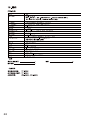
* 0 dB = 1 V
Note: The design and specifi cations are subject to change without notice for improvement.
• Accessories
Screwdriver (for setting) ............................ 1
Storage case ............................................. 1
Neck strap ................................................. 1
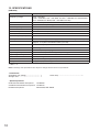
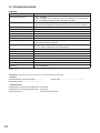
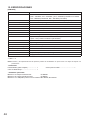
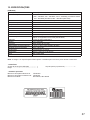
13. SPECIFICATIONS
[WM-5325]
Modulation Frequency modulation
Frequency Range
506 – 867 MHz
(506 – 538 MHz, 576 – 606 MHz, and 614 – 698 MHz for USA/Canada,
614 – 698 MHz for Brazil, 865 – 867 MHz for India)
Channel Selectable
64 channels (the number of channels may differ from country to country)
RF Carrier Power Less than 50 mW (Factory preset 10 mW ERP)
Tone Frequency 32.768 kHz
Oscillator PLL synthesized
Maximum Input Level –14 dB
*
to –29 dB
*
(Audio level control: Min. to Max.)
Maximum Deviation ±40 kHz
Audio Frequency Response 100 Hz – 15 kHz
Battery WB-2000 rechargeable battery (option) or AA alkaline dry cell battery
Battery Life Approx. 13 h (when the WB-2000 rechargeable battery is used)
Approx. 10 h (when the alkaline battery is used)
Indicator Power/Battery lamps
Antenna Built-in type
Connector ø3.5 mm (ø0.14") mini plug
Operating Temperature –10°C to +50°C (14°F to 122°F) (except battery)
Operating Humidity 30 % to 85 %RH
Finish Resin, coating
Dimensions 62 (w) x 102.5 (h) x 23 (d) mm (2.44" x 4.04" x 0.91")
Weight 90 g (0.2 lb) (with battery)
• Optional products
Unidirectional lavalier microphone: YP-M5300
Omnidirectional lavalier microphone: YP-M5310
Headset microphone: WH-4000A, WH-4000H

11
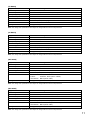
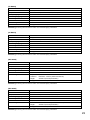
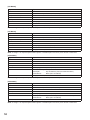
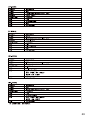
[YP-M5300]
[YP-M5310]
[WH-4000A]
[WH-4000H]
Type
Electret condenser type
Directivity Unidirectional
Sensitivity –66 dB ± 3 dB (0 dB =1 V/0.1 Pa, 1 kHz)
Maximum Input Level 120 dB SPL
Cord Length 1.3 m (4.27 ft)
Terminal ø3.5 mm (ø0.14") monaural plug
Finish Headband: EVA, black
Frame: Stainless, black (silicon rubber)
Gooseneck: Black (shrink tube)
Weight 50 g (0.11 lb) (cable included)
Type
Electret condenser type
Directivity Unidirectional
Sensitivity –63 dB ± 3 dB (0 dB =1 V/0.1 Pa, 1 kHz)
Frequency Response 100 Hz – 12 kHz
Maximum Input Level 120 dB SPL
Cord Length 1.3 m (4.27 ft)
Connector ø3.5 mm (ø0.14") mini plug
Finish Dark black
Weight 20 g (0.71 oz) (cable included)
Type
Electret condenser type
Directivity Omnidirectional
Sensitivity –64 dB ± 3 dB (0 dB =1 V/0.1 Pa, 1 kHz)
Frequency Response 100 Hz – 15 kHz
Maximum Input Level 110 dB SPL
Cord Length 1.3 m (4.27 ft)
Connector ø3.5 mm (ø0.14") mini plug
Finish Dark black
Weight 20 g (0.71 oz) (cable included)
Type
Electret condenser type
Directivity Unidirectional
Sensitivity –66 dB ± 3 dB (0 dB =1 V/0.1 Pa, 1 kHz)
Maximum Input Level 120 dB SPL
Cord Length 1.3 m (4.27 ft)
Terminal ø3.5 mm (ø0.14") monaural plug
Finish Frame: Stainless, black (silicon rubber)
Gooseneck: Black (shrink tube)
Weight 50 g (0.11 lb) (cable included)
Note: The design and specifications are subject to change without notice for improvement.
Note: The design and specifications are subject to change without notice for improvement.
Note: The design and specifications are subject to change without notice for improvement.
Note: The design and specifications are subject to change without notice for improvement.

12
Bedienungsanleitung
TASCHENSENDER
Wir danken Ihnen für den Kauf dieses Drahtlossenders von TOA.
Beachten Sie bitte stets die Anweisungen in dieser Bedienungsanleitung, um einen langen und
störungsfreien Betriebs des Geräts zu gewährleisten.
INHALTSVERZEICHNIS
1. SICHERHEITSHINWEISE ............................................................................ 13
2. ALLGEMEINE BESCHREIBUNG .............................................................. 15
3. LEISTUNGSMERKMALE ............................................................................. 15
4. VORSICHTSMASSNAHMEN BEI DER HANDHABUNG ................... 15
5. BEDIENELEMENTE ....................................................................................... 16
6. EINSETZEN DER BATTERIE ..................................................................... 18
7. BEI BETRIEB MIT EINER WIEDERAUFLADBAREN BATTERIE ... 19
8. KANALWAHL (CHANNEL) .......................................................................... 20
9. BEDIENUNG ..................................................................................................... 20
10. HINWEISE ZUM BETRIEB ........................................................................ 21
11. SPRECHABSTAND ...................................................................................... 21
12. PEGELEINSTELLUNG (EMPFINDLICHKEIT EINSTELLEN) ........ 21
13. TECHNISCHE DATEN ................................................................................. 22
WM-5325

13
Beim Gebrauch des Geräts
• Den Sender bitte nach Gebrauch immer ausschalten. Insbesondere ist darauf zu achten, dass es zu keiner
gegenseitigen Beeinflussung mit medizintechnischen Geräten kommt.
• Verwenden Sie zum Wiederaufladen das Batterieladegerät BC-5000 von TOA.
• Der Drahtlossender wird von einer Batterie des Typs WB-2000 mit Strom versorgt. Wenn jedoch eine
andere als die vorgeschriebene Batterie mit dem Batterieladegerät BC-5000 verwendet wird, kann diese
bersten oder auslaufen und einen Brand, eine Verletzung oder Verschmutzung verursachen.
• Die Verwendung eines anderen als das vorgeschriebene Batterieladegerät kann ein Bersten oder Auslaufen
der Batterie zur Folge haben und einen Brand, eine Körperverletzung oder Verschmutzung verursachen.
• Beenden Sie den Ladevorgang, wenn die Batterie nach drei Stunden nicht voll aufgeladen ist. Wird dies
versäumt, kann die Batterie sich entzünden, explodieren, auslaufen oder heiß werden.
• Achten Sie darauf, niemals die Ladeklemmen an der Unterseite des Senders mit einem Metallgegenstand
kurzzuschließen. Dies kann elektrische Schläge oder Verbrennungen zur Folge haben.
Zeigt eine potenziell gefährliche Situation auf.
Die Nichtbeachtung der Warnhinweise kann zu Verletzungen,
möglicherweise auch mit tödlichem Ausgang, führen.
WARNUNG
1. SICHERHEITSHINWEISE
• Lesen Sie die Sicherheits- und Warnhinweise in diesem Abschnitt vor Gebrauch unbedingt durch.
• Beachten Sie die Informationen in dieser Anleitung, da sie sehr wichtige Hinweise sowie Erläuterungen zu
den Sicherheitssymbolen und Signalwörtern enthalten.
• Wir empfehlen Ihnen außerdem, diese Bedienungsanleitung zum späteren Nachschlagen griffbereit
aufzubewahren.
Sicherheitssymbole und Signalwörter
In dieser Anleitung machen die nachstehenden Sicherheitssymbole und Signalwörter auf Gefahrenpunkte
aufmerksam, um Verletzungen und Sachschäden zu vermeiden, die durch unsachgemäße Handhabung
entstehen können. Bevor Sie das Produkt in Betrieb nehmen, lesen Sie daher zunächst diese Anleitung und
machen sich mit den Sicherheitssymbolen und Signalwörtern vertraut, um potenzielle Sicherheitsrisiken
erkennen zu können.

14
Zeigt eine potenziell gefährliche Situation auf.
Die Nichtbeachtung dieser Hinweise kann zu Verletzungen oder
Sachschäden führen.
ACHTUNG
Beim Gebrauch des Geräts
• Wenn das Gerät voraussichtlich 10 Tage oder länger nicht gebraucht wird, entfernen Sie unbedingt die
Batterie aus dem Gerät, da diese anderenfalls auslaufen, eine Verletzung oder Verschmutzung verursachen
könnte.
• Achten Sie darauf, dass bei der Handhabung die nachstehenden Vorsichtsmaßregeln eingehalten werden,
um einen Brand oder eine Verletzung durch Auslaufen oder Bersten der Batterie zu vermeiden.
· Die Batterie nicht kurzschließen, zerlegen, erhitzen oder verbrennen.
· Niemals versuchen, nicht wiederaufladbare Batterien zu laden.
· Batterien nicht anlöten.
· Unbedingt eine Batterie des vorgeschriebenen Typs verwenden.
· Beim Einlegen der Batterie in das Gerät auf korrekte Ausrichtung der Batteriepole (Plus und Minus) achten.
· Batterien nicht an Orten aufbewahren, wo sie direktem Sonnenlicht, hohen Temperaturen und hoher
Luftfeuchtigkeit ausgesetzt sind.
Legen Sie keine Trockenbatterien in das Ladegerät ein.
Wenn nicht wiederaufladbare Batterien in das Ladegerät gelegt werden, können sie bersten und einen Brand
und/oder eine Verletzung verursachen.
Verwenden Sie zum Wiederaufladen ausschließlich das Batterieladegerät BC-5000 mit Batterien des Typs
WB-2000.
Verwenden Sie keine anderen Batterietypen.
Sollte die Batterie anschwellen schwellen oder auslaufen, sehen Sie sofort von einer weiteren Nutzung ab und
ersetzen sie durch eine neue.
Sollte sich beim Laden der Batterie Rauch und/oder ein ungewöhnlicher Geruch entwickeln, schalten Sie das
Gerät unverzüglich aus.
Die Frequenzen zwischen 865 MHz und 867 MHz sind nicht CE-konform.
WARNHINWEIS: Der Versuch, Änderungen oder Modifikationen am Gerät vorzunehmen, die nicht von der
zuständigen Stelle genehmigt wurden, kann zu Schäden am Gerät führen und die Garantie erlischt.

15
2. ALLGEMEINE BESCHREIBUNG
Beim WM-5325 von TOA handelt es sich um einen Drahtlossender.
Das YP-M5300 und das YP-M5310 sind Lavaliermikrofone, während das WH-4000A und das WH-4000H als
Kopfbügelmikrofone ausgeführt sind; diese als Sprechmikrofone vorgesehenen Modelle sind als
Sonderzubehör erhältlich.
Das YP-M5310 verwendet ein Elektret-Kondensatormikrofonelement mit Kugelcharakteristik, während die
Modelle YP-M5300, WH-4000A und WH-4000H Elektret-Kondensatormikrofonelemente mit
Nierencharakteristik verwenden.
Der Unterschied zwischen dem WH-4000A und dem WH-4000H liegt darin, dass das WH-4000A Schweiß-
resistent ist und mit einer optionalen Gürteltasche geliefert wird.
3. LEISTUNGSMERKMALE
• Ein optimierter PLL-Synthesizer sorgt für stabile Sendefrequenzen auch bei sich ändernden
Umgebungsbedingungen.
• Mit dem Audiopegelsteller kann die Mikrofonempfindlichkeit verändert werden.
• Die Betriebs-/Batterieanzeige signalisiert den nötigen Batteriewechsel bei deutlichem Spannungsabfall,
bevor die niedrige Spannung zu Fehlfunktionen führen kann.
• Kompakt und zuverlässig.
• Schweiß-resistenter Kopfbügel mit verstellbarem Halteband speziell für Aerobic-Lehrer. (WH-4000A)
• Betrieb mit nur einer Batterie des Typs AA.
• Integrierte Antenne.
• Der Batterie-Ladezustand kann am Anzeigebereich des Tuners überprüft werden, wenn das Gerät in
Verbindung mit dem optional erhältlichen Drahtlosempfängers WT-5800, WT-5805 oder WT-5810 betrieben
wird.
4. VORSICHTSMAßNAHMEN BEI DER HANDHABUNG
• Verhindern Sie das Eindringen von Feuchtigkeit in den Sender um Fehlfunktionen oder Schäden zu
vermeiden.
• Service- oder Reparaturarbeiten sowie Eingriffe in das Gerät dürfen nur durch autorisiertes Fachpersonal
durchgeführt werden.
• Vermeiden Sie starke Stöße, die den Sender beschädigen könnten.
• Setzen Sie den Sender nicht hohen Temperaturen oder sehr hoher Luftfeuchtigkeit aus. Beides kann zu
Funktionsstörungen führen.
• Betreiben Sie den Sender nicht in Umgebungen, in denen es mit Seewasser in Berührung kommen kann.
• Reinigen Sie den Sender mit einem trockenen oder leicht angefeuchtetem Tuch. Wischen Sie den Sender
nach der Reinigung wieder trocken.
Verwenden Sie auf keinen Fall Lösungsmittel, Reinigungsbenzin oder sonstige chemische Reinigungsstoffe.
• Schalten Sie den Sender aus, solange Sie oder eine Person in Ihrer unmittelbaren Umgebung ein Handy
benutzen.
• Halten Sie zwischen mehreren Drahtlossendern einen Mindestabstand von 50 cm ein. Sie vermeiden damit
Fehlfunktionen oder Störgeräusche.
• Den Sender mindestens 3 m entfernt von der Empfangsantenne halten. Wenn der Sender in unmittelbarer
Nähe der Antenne verwendet wird, kann dies zu Störgeräuschen oder Funktionsstörungen führen.

16
5. BEDIENELEMENTE
Einheit: mm
19
23
62
98
Clip
Eingangsbuchse
Kanalwahlschalter
Lassen Sie den Schalter in der Position
“L” (Werkseinstellung).
Überlassen Sie die Schaltereinstellung
qualifizierten Kundendiensttechnikern.
Innerhalb einer Batterieabdeckung
Mikrofonempfindlichkeitssteller
Ein-/Ausschalter
Betriebs-/Batterieanzeige
Solange die Batteriekapazität ausreicht, leuchtet die
grüne LED auf.
Wenn die Kapazität abfällt, wird die grüne LED
schwächer; gleichzeitig leuchtet die rote LED auf.
Befestigung mit Nackenband
Nackenband
(Zubehör)

17
Clip
Arretierung
ø3,5 mm
Länge: 130 cm
Befestigung des Mikrofons am Clip
[Optionales Zubehör]
Lavaliermikrofon YP-M5310
Clip
Drehbar
Befestigung des Mikrofons am Clip
Arretierung
ø3,5 mm
Länge: 130 cm
Den engen Bund des
Mikrofons in die Halterung
des Ansteckclips einpassen.
Lavaliermikrofon YP-M5300

18
Arretierung
ø3,5
Windschutz
Bügel
Weiteneinstellung
Mikrofon
Länge: 130 cm
Kopfbügelmikrofon WH-4000A
Arretierung
Windschutz
Bügel
Mikrofon
ø3,5
Länge: 130 cm
Kopfbügelmikrofon WH-4000H
Gürteltasche WH-4000P
*
Der Windschutz WH-4000S ist als Sonderzubehör erhältlich.
6. EINSETZEN DER BATTERIE
Schritt 1. Den Sender ausschalten.
Schritt 2. Die Batterieabdeckung vom Gerät
abnehmen.
Die Batterieabdeckung in Pfeilrichtung
schieben, und gleichzeitig die Abdeckung
mit dem Daumen nach unten drücken,
wie in der Abbildung gezeigt.
Schritt 3. Eine Batterie des Typs AA entsprechend
den Batteriefach-Markierungen (+) und (–)
einlegen.
Schritt 4. Die Batterieabdeckung wieder anbringen.
Batteriewechsel
• Eine neue Alkalibatterie des Typs AA reicht für einen
Dauerbetrieb von ungefähr 10 Stunden.
• Wenn die Batteriekapazität abfällt, wird die grüne LED der
Einschalt-/Batterieanzeige schwächer; gleichzeitig leuchtet die
rote LED auf.
Wenn nur noch die rote LED leuchtet, muss die Batterie ersetzt
werden. In diesem Betriebszustand wird die Information über die
Restkapazität der Batterie zum Empfänger Übermittelt, worauf die
BATT-Anzeige des Empfängers aufleuchtet.
Rote LED Grüne LED

19
Betriebs-/Batterieanzeige
1
3
Hinweis
Kann nach vorne
odernach hinten
weisend eingesetzt
werden.
Ein-/Ausschalter
Ladeanzeige (rot)
Volladeanzeige (grün)
Hinweise
• Für den Betrieb mit wiederaufladbaren Batterien wird das optionale Batterieladegerät BC-5000 benötigt.
• Als wiederaufladbare Batterie muss die optionale Batterie des Typs WB-2000 verwendet werden.
Verwenden Sie keine anderen Batterien.
7.1. Ladeprozedur
Schritt 1. Stellen Sie den Hauptschalter des Drahtlossenders auf
OFF.
Hinweis
Schalten Sie den Hauptschalter des Drahtlossenders
zum Laden unbedingt aus. Wenn der Hauptschalter
auf ON (ein) steht, können Batterien nicht korrekt
geladen werden.
Schritt 2. Legen Sie die wiederaufladbare Batterie WB-2000 in
den Drahtlossender ein.
(Siehe S. 18, „Einsetzen der Batterie“.)
Schritt 3. Führen Sie den Drahtlossender bis zum Anschlag in
den Sendersteckplatz am Batterieladegerät BC-5000
ein.
Den Sender dabei so ausrichten, dass sein
Hauptschalter in Richtung der Vorder- oder Rückseite
des Ladegeräts weist.
Die Ladeanzeige am BC-5000 leuchtet rot, und der Ladevorgang beginnt.
Der Ladevorgang ist nach etwa drei Stunden abgeschlossen, und die Vollladeanzeige am BC-5000
leuchtet zur Bestätigung grün.
Hinweise
• Sollte die rote Ladeanzeige nach dem Einführen des Drahtlossenders in das Ladegerät nicht
leuchten, prüfen Sie, ob der Sender korrekt eingeführt wurde.
• Der Drahtlossender erwärmt sich nach Abschluss des Ladevorgangs, was jedoch normal ist.
Hinweis: Weitergehende Informationen entnehmen Sie bitte der dem Batterieladegerät BC-5000
beigepackten Bedienungsanleitung.
7.2. Aufladezeitpunkt
Bitte laden Sie das Gerät sofort, sobald beim Gebrauch die grüne LED
erlischt und die rote Lampe leuchtet.
Wenn die Batteriealarmlampe am Receiver leuchtet, ist die Restladung
der Batterie im Senders ebenfalls niedrig.
Der Sender wird einige Minuten lang nicht arbeiten.
Auch bei ausreichender Restladung der Batterie leuchten unter
Umständen die grüne und rote Lampe gleichzeitig.
[Richtwert zur Betriebszeit der wiederaufladbaren Batterie]
Dauerbetriebszeit: Ca. 13 Stunden
7. BEI BETRIEB MIT EINER WIEDERAUFLADBAREN BATTERIE
Legen Sie zum Aufladen ausschließlich die vorgeschriebene
Batterie des Typs WB-2000 in das Drahtlosmikrofon (Sender) ein.
Laden anderer Batterien als der Batterie des Typs WB-2000 kann
einen Brand oder eine Körperverletzung durch Bersten der Batterie
verursachen.
ACHTUNG
Hinweise
• Wenn Sie die wiederaufladbare Batterie WB-2000 zum ersten Mal verwenden, oder nach einem längeren
Nichtgebrauch, laden Sie die Batterie vor Gebrauch unbedingt auf.
• Die Batterie WB-2000 ist für etwa 500 Lade- und Entladezyklen konzipiert. Sollte die Sender-Betriebszeit
nach längerem wiederholten Gebrauch drastisch abnehmen, ersetzen Sie die Batterie durch eine neue.

20
9. BEDIENUNG
Schritt 1. Stecken Sie den Mikrofonstecker in die Buchse des Taschensenders und arretieren ihn wie
dargestellt.
Schritt 2. Vergewissern Sie sich, dass am Drahtlossender und am Drahtloseempfänger die gleichen
Kanalnummern eingestellt wurden. Wenn dies nicht der Fall sein sollte, den ON/OFF-Schalter auf
die OFF-Position schieben, dann die gleiche Kanalnummer wie am Tuner einstellen.
Schritt 3. Den ON/OFFSchalter auf die ON-Position stellen und sich danach vergewissern, dass die grüne
LED der Einschalt-/Batterieanzeige aufleuchtet.
Bei Verwendung der Gürteltasche WH-4000P wird der Sender wie in der unteren Abbildung rechts
gezeigt in der Tasche untergebracht.
Schritt 4. Nach der Verwendung des Senders den ON/OFF-Schalter auf die OFF-Position stellen.
Die Verbindung kann sich nicht lösen, wenn sie arretiert wird.
WM-5325
Haken und Schlaufe
Gürtel
Arretierung
Arretierung
WH-4000P
1
3
Kanalwählschalter
8. KANALWAHL (CHANNEL)
Schritt 1. Den Sender ausschalten, dann die Batterieabdeckung
abnehmen.
Schritt 2. Mit dem (mitgelieferten) Schraubendreher den
gewünschten Kanal einstellen. (Die Pfeilspitze
zeigt auf den gewählten Kanal).
Schritt 3. Batteriefachabdeckung schlieflen.
Hinweis
Falls Sie trotz eingeschaltetem Sender und Empfänger kein Signal empfangen: Überprüfen Sie, ob der
gewählte Kanal mit dem am Empfänger eingestellten Kanal übereinstimmt.
La pagina si sta caricando...
La pagina si sta caricando...
La pagina si sta caricando...
La pagina si sta caricando...
La pagina si sta caricando...
La pagina si sta caricando...
La pagina si sta caricando...
La pagina si sta caricando...
La pagina si sta caricando...
La pagina si sta caricando...
La pagina si sta caricando...
La pagina si sta caricando...
La pagina si sta caricando...
La pagina si sta caricando...
La pagina si sta caricando...
La pagina si sta caricando...
La pagina si sta caricando...
La pagina si sta caricando...
La pagina si sta caricando...
La pagina si sta caricando...
La pagina si sta caricando...
La pagina si sta caricando...
La pagina si sta caricando...
La pagina si sta caricando...
La pagina si sta caricando...
La pagina si sta caricando...
La pagina si sta caricando...
La pagina si sta caricando...
La pagina si sta caricando...
La pagina si sta caricando...
La pagina si sta caricando...
La pagina si sta caricando...
La pagina si sta caricando...
La pagina si sta caricando...
La pagina si sta caricando...
La pagina si sta caricando...
La pagina si sta caricando...
La pagina si sta caricando...
La pagina si sta caricando...
La pagina si sta caricando...
La pagina si sta caricando...
La pagina si sta caricando...
La pagina si sta caricando...
La pagina si sta caricando...
La pagina si sta caricando...
La pagina si sta caricando...
La pagina si sta caricando...
La pagina si sta caricando...
La pagina si sta caricando...
La pagina si sta caricando...
La pagina si sta caricando...
La pagina si sta caricando...
La pagina si sta caricando...
La pagina si sta caricando...
La pagina si sta caricando...
La pagina si sta caricando...
La pagina si sta caricando...
La pagina si sta caricando...
La pagina si sta caricando...
La pagina si sta caricando...
-
 1
1
-
 2
2
-
 3
3
-
 4
4
-
 5
5
-
 6
6
-
 7
7
-
 8
8
-
 9
9
-
 10
10
-
 11
11
-
 12
12
-
 13
13
-
 14
14
-
 15
15
-
 16
16
-
 17
17
-
 18
18
-
 19
19
-
 20
20
-
 21
21
-
 22
22
-
 23
23
-
 24
24
-
 25
25
-
 26
26
-
 27
27
-
 28
28
-
 29
29
-
 30
30
-
 31
31
-
 32
32
-
 33
33
-
 34
34
-
 35
35
-
 36
36
-
 37
37
-
 38
38
-
 39
39
-
 40
40
-
 41
41
-
 42
42
-
 43
43
-
 44
44
-
 45
45
-
 46
46
-
 47
47
-
 48
48
-
 49
49
-
 50
50
-
 51
51
-
 52
52
-
 53
53
-
 54
54
-
 55
55
-
 56
56
-
 57
57
-
 58
58
-
 59
59
-
 60
60
-
 61
61
-
 62
62
-
 63
63
-
 64
64
-
 65
65
-
 66
66
-
 67
67
-
 68
68
-
 69
69
-
 70
70
-
 71
71
-
 72
72
-
 73
73
-
 74
74
-
 75
75
-
 76
76
-
 77
77
-
 78
78
-
 79
79
-
 80
80


in altre lingue
- English: TOA WM-5325 User manual
- français: TOA WM-5325 Manuel utilisateur
- español: TOA WM-5325 Manual de usuario
- Deutsch: TOA WM-5325 Benutzerhandbuch
- português: TOA WM-5325 Manual do usuário