Hitec RCD IFHHFMS-CAR-75 Manuale utente
- Categoria
- Giocattoli telecomandati
- Tipo
- Manuale utente
Questo manuale è adatto anche per

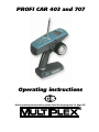
PROFI CAR 403 and 707
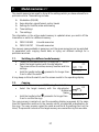
Operating instructions
Before operating the transmitter, please select the language (see 9.4, page 42)!

2
Dear customer,
dear fellow modeller,
we are delighted that you have decided to purchase a MULTIPLEX radio control system.
The „PROFI CAR“ is the first „pistol-grip“ transmitter designed and developed by MULTIPLEX.
Ergonomic efficiency and user-friendliness were our top priority during the development
process.
That’s not to say that we have neglected performance: the new system includes many
innovative and practical features, offering you facilities which until now have not been
available in systems of this class. They include:
v Interchangeable RF module, switchable to suit AM and FM receivers
v Up to 7 channels (steering, throttle/brake + 5 auxiliary channels)
v 2 steering servos and 2 brake servos (PROFI CAR 707 only)
v Separate throttle servo (PROFI CAR 707 only)
Of course, you don’t need to use these features; you can still operate the PROFI CAR as a
„completely normal“ set, i.e. with one steering servo and a second servo for throttle/brake.
We are confident that you will have many hours of pleasure with your PROFI CAR.
Yours the MULTIPLEX team
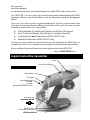
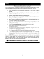
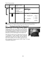
A quick look at the transmitter
Transmitter crystal
CAUTION:
Use only
genuine
MULTIPLEX
crystals
RF module
Charge socket
maximum 600 mA
ON/OFF switch
Aerial (screw fitting)
Menu buttons
Screen
Transmitter battery in base
With thermal fuse!

3
Contents
A quick look at the transmitter 2
Contents 3
Safety 5
System facilities 6
The transmitter controls in detail 7
The „instrument panel“ (screen) 8
The principle 9
Switching on for the first time 11
1.1. Charging the transmitter battery (maximum charge current 1 A) 11
1.2. Charging the receiver battery 11
1.3. Fitting the transmitter crystal 11
1.4. Adjusting the trigger loop 11
1.5. Testing the transmitter 12
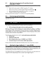
2. Short and to the point 12
2.1. Selecting the vehicle TYPE 13
2.2. Setting the servo norm, direction of rotation, travels and centre 14
2.3. Adjusting STEERING L 15
2.4. Adjusting THROTTLE A 15
2.5. Adjusting BRAKE A 16
3. More about steering LL 17
3.1. Adjusting the steering servo („T“ menu) 17
3.2. Adjusting the steering trim („T“ menu) 19
3.3. Adjusting the steering CENTRE, accepting the trim setting 19
3.4. Setting the minimum steering TRAVEL 20
3.5. SLOW 21
3.6. EXPO 21
3.7. Auto Dual Rates for steering 21
3.7.1. Reduced Travel RT at full throttle 22
3.7.2. Auto Dual Rate delay 22
3.8. The second steering servo (PROFI CAR 707 only) 22
4. More about THROTTLE AA 23
4.1. 2-point throttle curve with EXPO 23
4.2. 5-point throttle curve 24
4.3. Automatic Start 25
4.3.1. Setting the „addition“ for Initial Throttle „IT+“ 25
4.3.2. Initiating the automatic start function using the trigger 26
4.3.3. Initiating the start function with the handle button or trigger 26
4.3.4. Terminating the automatic start phase 26
4.4. TC = traction control (nur PROFI CAR 707) 27
5. More about BRAKE 28
5.1. Two-point brake curve with EXPO 28
5.2. Trimming the Lock Point LP using rocker D 29
5.3. ABS = Advanced Braking System (PROFI CAR 707 only) 30
5.4. Braking with more than one servo (PROFI CAR 707 only) 31

4
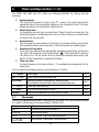
6. Timers and lap counters ºº 0000 33
6.1. Timer mode 33
6.2. Lap time memory 34
6.3. Setting the nominal time T-NOM 35
6.4. Setting the race duration (timer mode 3 only 35
6.4.1. Race duration by laps 35
6.4.2. Race duration by time 35
6.5. Checking the transmitter’s operating time 36
6.6. Erasing the timer ERASE 36
7. Model memories 11 37
7.1. Switching to a different model memory 37
7.2. Copying 37
7.3. Entering the model name 38
7.4. Erasing 38
7.5. Reverting to the PREVious state 38
8. Driving trucks 39
8.1. Selecting the model type 2+5 CH (truck) 40
8.2. Setting the control mode for the auxiliary channels 40
8.3. Adjusting travel and centre of the auxiliary channels 41
8.4. Truck steering and throttle/brake 41
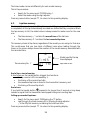
9. The “toolbox” TT 41
9.1. Adjusting the trigger deadband („T “ menu, DEADB) 41
9.2. Switching between AM and FM („T “ menu, AM-FM) 42
9.3. Entering the owner’s name („T “ menu, NAME) 42
9.4. Selecting the display language („T “ menu, TEXT) 42
9.5. Setting the battery alarm threshold („T “ menu, ALARM) 42
10. Tips on installing the receiving system in the model 43
11. The system in use 44
11.1. Post Office Regulations for the U.K. 44
11.2. Range testing 44
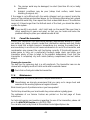
11.3. Care of the transmitter 45
11.4. Maintenance 45
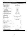
Specification, system characteristics 46
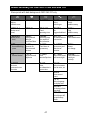
Menu summary for the PROFI CAR 403 and 707 47

5
Safety
Radio-controlled models are not toys!
You can make a major contribution to safety when operating your models by acting
responsibly and handling your radio control system and model with due care.
v Check the electrical and mechanical connections in the model at regular
intervals.
v Check all moving parts regularly: they must be free to move, and must not
exhibit undue lost motion.
v Carry out regular range checks (see „Range testing“).
v When other drivers are present at the track, find out which channels are
already in use before you switch on.
v Before every run: extend the transmitter aerial to full length, and check that
it is in good condition and firmly seated.
v Check that you have selected the model memory corresponding to the
model you are running.
v Check all the working systems in your model before you start:
Do the servos rotate in the correct direction?
Are the travels correct?
v Are the transmitter and receiver battery adequately charged, and in well
maintained and roadworthy condition?
v Use only genuine MULTIPLEX crystals, batteries and accessories.
v If your receiving system includes components which are not covered by
these operating instructions, be sure to read the instructions supplied with
those items.
If you are in doubt on any point - don’t operate your model! Take your time, carefully
check the system again, and eliminate the fault. If you cannot solve the problem,
your local model shop or the MULTIPLEX customer service department will be
pleased to help you with advice and practical help.
!!
Read and observe the notes in Chapter 11 on using the system!

6
System facilities
403 707
Model memories 6 12
Copy, reset, erase, enter model name
Steering
SLOW, separate for entering and exiting turns ü ü
EXPOnential steering curve (progressive / degressive) ü ü
Variable CENTRE and TRAVEL ü ü
Variable steering trim increment ü ü
Second steering servo - ü
Throttle
Automatic start system ü ü
EXPOnential throttle curve (progressive / degressive) ü ü
Separate THROTTLE / BRAKE servos - ü
5-point throttle curve ü ü
Traction-Control TC - ü
Brake
Variable engage point and lock point ü ü
EXPOnential brake curve (progressive / degressive ) ü ü
ABS (Advanced Braking System) - ü
Second brake servo (front / rear) - ü
Timer and lap counter
Operating time ü ü
Race duration by time / lap ü ü
Lap counter ü ü
Lap time memory 5 50
Mechanical features
Programmable trigger deadband
High-grip steering wheel lining
Ergonomic controls mounted on the handle
Angled screen for optimum legibility
Light weight
Signal transmission
FM or AM transmission, selectable for each model memory
Plug-in RF module (40/41 MHz and 72 MHz)
Externally accessible plug-in transmitter crystal
Power supply
600 mAh / 6-cell battery, approx. 3 hours operating time
Charge socket in transmitter base

7
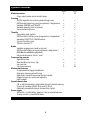
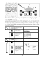
The transmitter controls in detail
The three pictures below illustrate the essential controls.
The menu buttons
The trigger duster
The trim rockers
Repeat function
All trim rockers have an automatic repeat function when held pressed for longer than
about 1 second.
Special case – TRUCK:
If you wish to control a truck with your Profi Car, you have 5 auxiliary channels
available (see 8: Driving trucks). In this mode only the steering trim (rocker A) is
active; all the other rockers are used to control the auxiliary channels.
HB
Handle Button
DA
Digi Adjustor
DA HB
Steering
Initial throttle
Lock point
rear brake
(throttle/brake servo)
Switched channel or
lock point front brake
(2
nd
brake servo)
The
„tuning centre“
Everything to hand
The „key“
to the menus
Trigger loop
adjustment screw

8
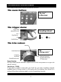
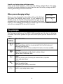
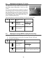
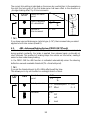
The „instrument panel“ (screen)
The picture below shows everything which the screen can display. What you actually
see at any one time depends on what you are doing: whether timers are active,
whether you are currently programming the transmitter, which type of vehicle you
have selected, etc.
A few examples are shown on this page.
Operating display
Timer mode: OFF
If no timer function is active, the first text line displays the
model name you have entered. Text line 2 shows the
transmitter battery voltage.
Timer Mode: LAP
The second text line shows the number of the lap on the left-
hand side. To record the start and end of each lap you press the
handle button
G
.
Timer-Mode: L+T (Laps + Time memory)
In this mode the second text line shows the number of the lap
on the left (in our example 03) and the time for the current lap
on the right (in our example 28.3 sec).
Timer-Mode: L+T+E (Laps + Time memory + Race duration)
The first text line displays the total duration of the race (in our
example 2 min. 36.5 sec). The second text line shows the
number of laps and the time of the current lap, as in the
previous example.
STV =
Steering travel
IT = Initial Throttle
STR =
Steering TRim
Brake 1
Brake 2
Text line 1
Number of
Active
model memory
Text line 2
BUGGY
7.4V
BATT
BUGGY
03 7.4V
LAP
BATT
BUGGY
03 28:3
LAP
2:36:5
03 28:3
LAP
Menu
symbols

9
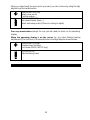
Special case: battery alarm with timer active
If one of the timer modes is active and the battery voltage falls to the alarm
threshold, the screen displays the current lap time and the battery voltage and BATT
warning, alternating at 2-second intervals.
When you are changing settings
When you are changing the transmitter settings, the first text
line shows the selected menu point (in our example: the
throttle curve). On the left of the second text line you see the
parameter which you have selected with the help of the handle
button (in our example full throttle). At bottom right the screen shows the current
value (in our example 87%) above the % symbol
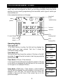
The principle
The five menu buttons on the PROFI CAR transmitter are the key to all set-up
processes. The button symbols tell you which menu points you can access with each
button.
Menu
button
Menu function
A
TRIGGER
Adjust everything which is concerned with the throttle, brake and
automatic start function;
on the PROFI CAR 707 it also includes TC (Traction Control) and ABS
L
STEERING
Adjust the steering to suit the track / vehicle / driver
Centre, travel, Dual Rates, Slow
U
TIMER
Select the timer mode (T-mode), set nominal time / lap data
Check and erase times
T
TOOLS
Select the vehicle type
Basic settings for servos, transmitter
F
MEMORY
Switch, copy, assign name, erase
G-CURV
FT 87
%

10
When you have found the menu point you want, you can continue by using the digi-
adjustor and the handle button.
HANDLE BUTTON (HB)
Select curve points
Confirm erasure, ...
DIGI-ADJUSTOR (DA)
Set values (travels, times, ...)
Select sub-menu points (if there is nothing to adjust)
Press any menu button (except the one you last used) to return to the operating
display.
When the operating display is on the screen (i.e. you have finished making
adjustments), the functions of the handle button and digit-adjustor are as follows:
HANDLE BUTTON (HB)
Operate timer functions
Lock brake (PROFI CAR 707 only)
DIGI-ADJUSTOR
Adjust steering travel

11
Switching on for the first time
1.1. Charging the transmitter battery (maximum charge current 1 A)
First connect the charge lead (Order No. 12 5023) to the battery charger, then
connect the charge lead to the transmitter.
Charging the battery – important:
•• Automatic battery fuse
The battery of your PROFI CAR features an integral thermal fuse which protects the
battery from excessive currents if a short-circuit should occur.
This transmitter must be used with a genuine MULTIPLEX battery
fitted with this type of fuse!
!!
If a short-circuit occurs and the fuse trips, the fuse element will reset itself about
1 minute after the fault is corrected, and the unit will then work again normally.
•• Charging the battery - note:
If you charge at the standard (slow) rate, no restrictions apply.
If you fast-charge the battery using a charger with automatic termination, the charge
current must not exceed 600 mA. Exceeding this rate may cause the thermal fuse to
trip, and the charge process will be interrupted prematurely.
1.2. Charging the receiver battery
Observe the manufacturer’s notes on charging, as printed on the battery.
Do not exceed the stated charge currents!
1.3. Fitting the transmitter crystal
Transmitter crystals have a blue sleeve and bear the code letter „S“ before the
channel number. Ensure that the transmitter and receiver crystals are on the same
channel.
Plug the transmitter crystal into the RF module (see picture on page 2).
Please be very careful when handling crystals:
v Don’t drop them
v Don’t force a crystal into its socket
v Protect them from vibration in use and in storage
1.4. Adjusting the trigger loop
You can adjust the trigger loop to suit your finger size by loosening the screw in the
trigger.
CAUTION: don’t over-tighten the screw after making the adjustment, as this could
loosen the nut pressed into the other side!

12
1.5. Testing the transmitter
Now you can switch on the transmitter and a receiving system and generally try
things out. All you need is a receiver, two servos connected to channels 1 and 2, and
a battery. If you prefer to use an existing model car, make sure that the steering servo
is connected to channel 1 and the throttle/brake servo to channel 2.
Now you can continue with Section 2.
2. Short and to the point
In this section you will discover the five simple steps required to get your first model
car „up to speed“. This is the procedure in brief:
2.1 Select the vehicle type
Adjust the transmitter to suit the model (number of channels, ...)
2.2 Set the servo norm, centre and travels
Adjust the servos to suit the mechanical system in your model
(the „S-NORM“ menu point includes direction of rotation)
2.3 Adjust the steering set up to suit your
2.4 Adjust the throttle personal preferences
2.5 Adjust the brake and the track characteristics

13
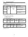
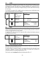
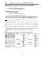
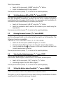
2.1. Selecting the vehicle TYPE
Selecting the vehicle TYPE determines the channels which are to be used to control
your model.
The PROFI CAR 403 offers the following options.
TYPE Steering Throttle + Brake Special features
STANDSTAND
e.g.
electric car
EXPO on THROTTLE
Switched channel for servo 3
2+1 CH2+1 CH
GP car
5-point curve for THROTTLE
Switched channel for servo 3
2+5 CH2+5 CH
Truck
Servo
1
Servo
2
Switched channels for servo 3 to 7
EXPO on THROTTLE
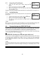
The PROFI CAR 707 also includes:
v ABS Advanced Braking System
v TC Traction Control
v and two new vehicle types:
TYPE Steering Throttle/brake 2
nd
brake Special features
4 CH4 CH
Servo
1 + 4
Servo
2
Servo
3
2
nd
brake servo on channel 3
5-point curve on THROTTLE
no auxiliary channel
TYPE Steering Throttle Brake Special features
5 CH5 CH
Profi
Servo
1 + 5
Servo
2
Servo
3 + 4
2 steering and 2 brake servos
5-point curve on THROTTLE
no auxiliary channel
For your first attempts we recommend that you select the vehicle type STAND
(standard) or 2+1 CH.

14
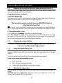
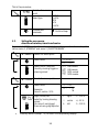
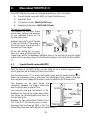
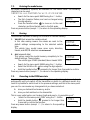
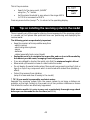
This is the procedure:
TYPETYPE
Search for menu
point
Select type
STAND
2+1CH
4CH
5CH
2+5CH
Confirm and
terminate
X Confirm. Beep
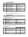
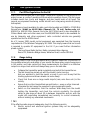
2.2. Setting the servo norm,
direction of rotation, travels and centre
If you select STAND or 2+1 CH as the vehicle type, all you need to do is set up the
servos: servo 1 „STEERING“ and servo 2 „THROTTLE/BRAKE“.
SS --NORMNORM
Search for menu point
Select servo
S-NORM
2: MR
Select norm / direction,
check by moving trigger or
steering wheel
UN UNI normal
UR UNI reverse
MN MPX normal
MR MPX reverse
SS --TRAVTRAV
Search for menu point
Select servo
Example:
Servo 2, centre –12%
S-TRAV
2: • -12
%
L A
Right, centre, left
select by turning steering
wheel
(for servo 2 use trigger)
then set using digi-adjustor
ŒŒ right 0 – 100 %
•• centre +/- 25 %
LL left 0 – 100 %
§ Press any button (except T ) to return to the operating display.

15
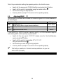
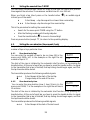
2.3. Adjusting STEERING LL
Steering settings:
CECENTRNTR
Servo centre (straight ahead) - 50% to + 50%
TRAVTRAV
Minimum steering travel,
if set using digi-adjustor
30% to 100%
DUALDUAL
Auto Dual Rates
DE = delay 0 to 5
RT = reduced travel
Switch off with „DE = 0“
50% to 100%
SLOWSLOW
Retards steering movements
Enter/exit turn separately
0.0 sec to 1.0 sec
EXPOEXPO
Exponential steering curve
+100% = soft
-100% = hard
§ Use the L button to search for the menu point SLOW, EXPO, CENTR or
TRAV
§ Set the value you want using the digi-adjustor
§ Press any button (except L ) to return to the operating display.
2.4. Adjusting THROTTLE AA
You must set either a 2-point or 5-point throttle curve, depending on the vehicle
type you have selected.
For the STANDard and TRUCK vehicle types:
2 point throttle curve
with EXPO
LL
Idle 0% to 100%
IT
Initial throttle =
initial throttle value when trigger
leaves deadband
0% to 100%
FT
Full Throttle 0% to 100%
EXP
Exponential throttle curve
+100% = soft start
-100% = hard start
For the vehicle types „2+1 CH“, „4 CH“ and „5 CH“
5-point throttle curve
Range Default setting
ID
Idle 0% to 50 % 15%
IT
Initial throttle = initial throttle value
when trigger leaves deadband
0% to 100% 30%
2T
3T
4T
Points on the throttle curve 0% to 100%
45%
60%
75%
FT
Full throttle 0% to 100% 100%

16
This is the procedure for setting the separate points on the throttle curve:
§ Search for the menu point T-CURV (throttle curve) using the A button
§ Search for the point to be adjusted using the handle button
G
§ Set the value using the digi-adjustor
§ Press any button (except A ) to return to the operating display
2.5. Adjusting BRAKE A A
The settings for the brake are the same for all vehicle types. EXPO is also available in
all vehicle types.
Point to be adjusted Range
EPEP
Engage Point =
Brake setting when trigger leaves deadband
0% to 100%
LPLP
Lock point 0% to 100%
EXPEXP
Exponential brake curve ±100%
IF you set EXPO to +100% the brake is applied „gently“; at -100% the brake is applied
hard. Setting EXPO to 0% switches exponential off.
§ Search for the menu point BREMS1 (brake curve for the throttle/brake
servo) using the AA button.
§ Search for the point to be adjusted (EP/LP/EXP)
using the handle button
G
.
§ Set the value you want using the digi-adjustor
§ Press any button (except A ) to return to the operating display
üü That’s all you need to do. It should now be possible to run your car
and control it properly.

17
3. More about steering LL
The PROFI CAR provides the following facilities for adjusting the steering:
• Servo centre and servo travel {3.1} (T menu, menu point „S-TRAV“, servo 1)
These facilities allow you to adjust the servo to suit the mechanical set-up in your
model, and at the same time set the maximum steering travel and centre setting
for accurate straight running.
• Steering CENTRE {3.3} (L menu, menu point „CENTRE“)
In this part of the menu you can correct the car’s straight running. The steering
trim also affects this value, and you can „automatically“ accept the trim value as
the centre in this menu point.
• Steering TRAVEL {3.4} (L menu, menu point „TRAVEL“)
At this point you can enter a value for the minimum steering travel which you
can set using the digi-adjustor when the car is running. This avoids the danger of
inadvertently setting such a low value that you suddenly run out of steering
travel when you most need it. 30% is the minimum value.
• SLOW {3.5} (L menu, menu point „SLOW“)
You can adjust the transit speed of the steering servo separately for entering
turns „••“ and for exiting turns „••“.
• EXPO {3.6} (L menu, menu point „EXPO“)
You may like to adjust the steering so that response to the wheel is more or less
sensitive than normal around the centre setting. This is achieved by setting a
value for EXPOnential.
• Auto Dual Rates (L menu, menu point „DUAL“)
Dual Rates means reduced servo travel, and Auto Dual Rates means that the
travel of the steering servo is reduced automatically when the throttle setting is
increased. At full throttle steering travel is small, at idle steering travel is large.
At the DUAL menu point you can
1. set the value at which reduced steering travel (RT) takes effect
2. set the delay (DE) which applies to the automatic travel reduction
• Increment size for steering travel and trim setting {3.2}
(T menu, menu point „STEP“)
Each movement of trim rocker A (steering centre) and of the digi-adjustor
(steering travel) produces one increment of change; the step size can be set to
any value between fine (1% increments) and coarse (10% increments).
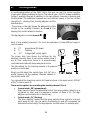
3.1. Adjusting the steering servo („TT“ menu)
You must adjust the servo to suit the mechanical set-up in your model before you
alter the steering settings in the L menu. In more detail this means: setting the
direction of rotation / and pulse width (norm) of the servo, and setting appropriate
values for left ( ), straight ( ) and right.

18
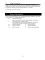
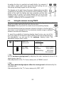
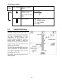
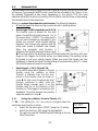
The diagram on the right
shows an example of the
settings you can change in
the „S-TRAV“ menu. The
stated angles (0° / 45°) show
the servo’s maximum phy-
sical travel. The adjustment
points „LL “ and „ŒŒ “ indicate
the maximum travel of the
steering servo which the
user has set. To adjust either
of these points you have to
turn the steering wheel in
the corresponding direction.
When the servo is at the „•• “ point you can adjust the servo setting for „straight“.
In the „S-NORM“ menu point
you can also set the direction of rotation for the servo, and choose between the
MULTIPLEX and UNIVERSAL signal formats. MULTIPLEX norm means that the signal
length (pulse width) for the centre setting is 1.6 ms, and the signal range is
+/- 0.55 ms. The UNIVERSAL norm means that the servos operate on 1.5 ms +/-0.5 ms.
This is the procedure:
SS --NORMNORM
Search for menu
point
Select servo 1
S-NORM
1: MR
Select norm and
direction of
rotation
UN UNI normal
UR UNI reverse
MN MPX normal
MR MPX reverse
SS --TRAVTRAV
Search for menu
Point
Select servo 1
S-TRAV
1: •- 3
%
L
Select right, centre,
left by rotating
steering wheel,
then set using digi-
adjustor
ŒŒ right 0 – 100 %
• • centre +/- 25 %
L L left 0 – 100 %

19
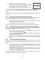
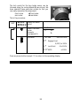
3.2. Adjusting the steering trim („TT“ menu)
The steering is trimmed using the trim rocker A. You
can easily find this rocker „blind“ because its shape
and fluted surface differentiate it from the other
rockers
You can use the steering trim to adjust the centre of
the steering servo by 7 increments in each direction.
Each step offsets the centre by at least 1% (fine) and
at most 10% (coarse). You can select the size of the
trim increments in the menu point STEP of the „*“
menu. The default setting is 2%.
The screen shows the current trim settings in the form of a vertical bar.
T
STEPSTEP
Serrate for menu
point
Search for
parameter
STR =Steering TRim
STEP
STR 2
%
Set size of
trim increment
1 – 10%
3.3. Adjusting the steering CENTRE, accepting the trim setting
In this menu point you can do two things:
v Set the steering servo centre within the range -50% and +50%, and
v accept the trim setting
L
CENTRECENTRE
Search for menu
point
Set the centre
(e.g.: -8%)
CENTRE
- 8
%
> 3 sec
Accept the trim
setting as centre
The current trim value is added to
the centre, and then reset to zero.

20
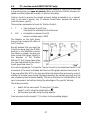
Accepting the trim is a practical and useful facility. For example, if
you suffer a „slight crash“ which knocks the basic setting out, you
can quickly and simply regain the full trim range.
The diagram on the right shows the screen display before and after
accepting the trim setting. On the left the centre is offset by 3 steps,
while on the right the setting has been accepted, and the trim
display is back to centre. If you have selected, say, 3% as the trim
increment when trimming the steering centre SC, this means that
„CENTRE“ is offset by 9% (3 increments of 3%).
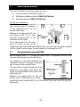
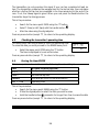
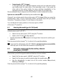
3.4. Setting the minimum steering TRAVEL
During a race you can alter the steering travel with the digi-adjustor, so that it is
always accurately matched to the track you are using.
Please note: this only works if the screen shows the operating display!
The actual steering travel you have set is shown by the bar on the far right of
the screen. In our example 2/3 of the maximum possible range is available
between minimum and maximum.
To avoid the possibility of reducing steering travel to zero, you can at this
point set a value for the extent to which steering travel can be reduced using
the digi-adjustor, i.e. you can fix the minimum steering travel. The
adjustment range is 30% to 100%.
L
TRAVELTRAVEL
Search for
menu point
TRAVEL
72
%
Set travel
(e.g.: 72%)
Range: 30% to 100%
Increment: 1% to 10%%
Default setting: 44% travel
2% increment
' TIP !
Set the maximum steering travel by adjusting the basic mechanical set-up of the
steering servo (see 3.1).
Make adjustments in the „T“ menu, menu point „S-TRAVEL“, servo 1.
' TIP !
The rate at which the digi-adjustor affects the steering travel
is determined by the
increment size.
Make adjustments in the „T“ menu, menu point „STEP“, „STV“
La pagina si sta caricando...
La pagina si sta caricando...
La pagina si sta caricando...
La pagina si sta caricando...
La pagina si sta caricando...
La pagina si sta caricando...
La pagina si sta caricando...
La pagina si sta caricando...
La pagina si sta caricando...
La pagina si sta caricando...
La pagina si sta caricando...
La pagina si sta caricando...
La pagina si sta caricando...
La pagina si sta caricando...
La pagina si sta caricando...
La pagina si sta caricando...
La pagina si sta caricando...
La pagina si sta caricando...
La pagina si sta caricando...
La pagina si sta caricando...
La pagina si sta caricando...
La pagina si sta caricando...
La pagina si sta caricando...
La pagina si sta caricando...
La pagina si sta caricando...
La pagina si sta caricando...
La pagina si sta caricando...
La pagina si sta caricando...
-
 1
1
-
 2
2
-
 3
3
-
 4
4
-
 5
5
-
 6
6
-
 7
7
-
 8
8
-
 9
9
-
 10
10
-
 11
11
-
 12
12
-
 13
13
-
 14
14
-
 15
15
-
 16
16
-
 17
17
-
 18
18
-
 19
19
-
 20
20
-
 21
21
-
 22
22
-
 23
23
-
 24
24
-
 25
25
-
 26
26
-
 27
27
-
 28
28
-
 29
29
-
 30
30
-
 31
31
-
 32
32
-
 33
33
-
 34
34
-
 35
35
-
 36
36
-
 37
37
-
 38
38
-
 39
39
-
 40
40
-
 41
41
-
 42
42
-
 43
43
-
 44
44
-
 45
45
-
 46
46
-
 47
47
-
 48
48


Hitec RCD IFHHFMS-CAR-75 Manuale utente
- Categoria
- Giocattoli telecomandati
- Tipo
- Manuale utente
- Questo manuale è adatto anche per
in altre lingue
- English: Hitec RCD IFHHFMS-CAR-75 User manual
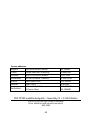
Documenti correlati
Altri documenti
-
Spektrum DX2S DSM 2-Ch Transmitter and Receiver Manuale utente
-
Spektrum SR300 Manuale utente
-
-
MULTIPLEX Royal Sx 16 Elegance Manuale del proprietario
-
-
-
Carson Reflex Wheel Pro LCD 3 Manuale utente
-
 Scalextric digital ADVANCED 6 CAR POWERBASE Manuale utente
