MULTIPLEX Royal Sx 16 Elegance Manuale del proprietario
- Categoria
- Giocattoli
- Tipo
- Manuale del proprietario

MULTIPLEX Modellsport GmbH & Co.KG • Westliche Gewerbestraße 1 • Bretten • Germany
© MULTIPLEX 2014 • Printed in Germany
www.multiplex-rc.de
Instructions


19.11.2008 1
1. Contents
1. Contents 1
2. Introduction 5
2.1. The ROYAL SX philosophy ...................... 6
2.2. Arrangement of the instructions ............. 6
3. Safety Notes 7
3.1. General safety notes ................................. 8
3.2. Range checking ......................................... 9
4. Liability / Compensation 10
5. Guarantee 10
6. CE Conformity Declaration 10
7. Specification 11
8. The Transmitter Battery 11
8.1. Safety Notes ............................................. 11
8.2. Charging the transmitter battery ........... 11
8.3. The correct method of charging ............ 12
8.4. ROYAL SX battery management ............ 12
8.4.1. Self-discharge 12
8.4.2. Unchanged features 13
8.4.3. This is important 13
8.5. Terms used in battery charging ............. 13
8.5.1. Normal charging … 13
8.5.2. Fast charging … 13
8.5.3. Trickle charging … 14
8.6. Replacing the transmitter battery .......... 14
8.7. Transmitter battery care and storage .... 14
8.8. Recycling ................................................. 14
9. The Transmitter 15
9.1. Front face of the transmitter .................. 15
9.2. Rear face of the transmitter ................... 16
9.3. Interior of the transmitter ....................... 16
9.4. Mechanical details ................................... 17
9.4.1. Opening / closing the transmitter case 17
9.4.2. Removing / installing the RF module 17
9.4.3. Ideal Transmitter Aarial Orientation When Using the
Transmitter 18
9.4.4. Replacing the transmitter battery 18
9.4.5. Disabling the stick centring spring, activating the
ratchet / friction system 19
9.4.6. Adjusting the “hardness” of the sticks 19
9.4.7. Swivelling the stick units 19
9.4.8. Adjusting / replacing the stick tops 19
9.5. Plastic stick top with three buttons:
installation and functions ...................... 20
9.6. Digital trims .............................................. 20
9.6.1. General information 20
9.6.2. Advantages of digital trims 21
9.6.3. The cruciform digital trims 21
9.6.4. On-screen trim display 21
10. Switching on, using the transmitter 22
10.1. Switching on for the first time ................ 22
10.2. Switching on “normally” ......................... 22
10.2.1. Normal OpartionsFehler! Textmarke nicht definiert.
10.2.2. RF module excl. Scanner installed 22
10.3. Switching the transmitter on with throttle-
check active............................................. 22
10.3.1. Throttle-check for fixed-wing models 22
10.3.2. 23
10.3.2. Throttle-check for model helicopters 23
10.4. Binding Procedure................................... 23
10.5. Range Checking ....................................... 23
10.6. Fast Response ON/OFF .......................... 24
10.7. The Status displays ................................. 24
10.7.1. Status display 1 (standard) 24
10.7.2. Status display 2 (flight phases) 24
10.7.3. Status display 3 (timers) 25
10.7.4. Status display 4 (system information) 25
11. The “ROYAL SX” philosophy 25
11.1. Operating the ROYAL SX ........................ 25
11.1.1. Using the keypad 25
11.1.2. Using buttons when operating a model 26
The............................................................. 26
11.2. ROYAL SX menu structure ..................... 26
11.3. What do the sticks, sliders and switches
do? Or: Global assignments (lists) ....... 27
11.3.1. What does “Assignment” mean? 27
11.3.2. What are transmitter controls? 27
11.3.3. What are switches? 27
11.3.4. Why “global” assignments? 27
11.3.5. Which assignment lists are available? 28
11.3.6. How are the assignment lists arranged? 28
11.3.7. How are the assignment lists used? 28
11.3.8. Summary: “Global assignments” 29
11.4. Global mixer definitions .......................... 29
11.4.1. Why “global” mixer definitions? 29
11.4.2. Which global mixers are available? 29
11.4.3. Mixer names with a “+” suffix 29
11.4.4. How are the free mixers used in fixed-wing model
aircraft? 29
11.4.5. How are mixers used in helicopters? 30
11.4.6. Summary of the “free mixers” 30
11.5. Model templates ....................................... 30
11.5.1. Why are model templates needed? 30
11.5.2. What do the model templates contain? 30
11.5.3. Which model templates are available? 30
11.6. Servo configuration ................................. 30
11.7. Servo calibration ...................................... 31
11.7.1. What can be calibrated? 31
11.7.2. How is the calibration carried out? 31
11.7.3. Allocation - what’s that? 31
12. Setting up a fixed-wing model 32
12.1. The method in principle .......................... 32
12.2. Setting up the new model in the
transmitter ............................................... 32
12.2.1. Menu I, call up New model 32
12.2.2. Which model memory will be used? 32
12.2.3. Selecting the Template 32

ROYAL SX
2
12.2.4. Selecting the servo configuration (servo conf.)32
12.2.5. Selecting the stick mode 33
12.2.6. Selecting the Assignment 33
12.2.7. Confirming with OK 33
12.2.8. Entering the model name 34
Preparing the controls / switches .......... 34
12.3. 34
12.3.1. Selecting / changing the idle position for spoiler /
throttle 34
12.3.2. Changing the switch ON position 35
12.4. Preparing servos ..................................... 35
12.4.1. Checking / changing the servo assignment 35
12.4.2. Checking / changing the direction of servo rotation36
12.4.3. Calibrating servos = setting the centre and
maximum travels 36
12.5. Adjusting ailerons, and activating landing
aid (Mixer AILERON+) .............................. 37
12.6. Differential aileron travel ........................ 38
12.6.1. Activating differential 38
12.6.2. Setting the differential value 38
12.7. Adjusting elevator, activating elevator
mixers (Mixer ELEVATR+) ........................ 39
12.7.1. Spoiler to elevator = Spoiler compen-sation
(Spoiler input to ELEVATR+ mixer) 39
12.7.2. Throttle to elevator = Throttle compen-sation (Thr
-Tr input to ELEVATR+ mixer) 39
12.8. Activating inboard flaps (camber-
changing flaps) (Mixer FLAP+) ............... 39
Activating the Spoiler input in the mixer FLAP+
( 40
12.8.1. Butterfly) 40
12.8.2. Activating the Flap input in the mixer FLAP+
(camber-changing flaps) 40
12.8.3. Activating the Aileron input in the FLAP+ mixer
(aileron support by the inboard (camber-changing)
flaps) 40
12.8.4. Activating the Elevator-Tr (Ele -Tr) input in the
FLAP+ mixer (snap-flap) 41
12.9. V-tail models ............................................ 41
12.9.1. Assigning V-tail servos 41
12.9.2. Activating the mixer V-TAIL+ 41
12.9.3. 41
12.9.3. Checking / changing the direction of servo rotation41
12.9.4. Adjusting the remaining inputs 42
Working with flight phases ................. 42
12.10. 42
12.10.1. What is the purpose of switching between different
flight phases? 42
12.10.2. Default settings in the menu Flight phase 42
12.10.3. Assigning flight phase switches 42
12.10.4. Locking / unlocking flight phases 42
12.10.5. Copying flight phases 43
12.10.6. Changing flight phase names 43
12.10.7. Setting a transition time 43
12.11. Supplementary functions ....................... 44
12.11.1. D/R and Expo 44
12.11.2. Activating Combi-Switch 44
12.11.3. Motor run timer 44
13. Setting up a model helicopter 45
13.1. The method in principle .......................... 45
13.2. Setting up a New model in the transmitter45
13.2.1. Menu I, call up New model 45
13.2.2. Which model memory will be used? 45
13.2.3. Selecting the template 45
13.2.4. Selecting the servo config(uration) 45
13.2.5. Selecting the stick Mode 46
13.2.6. Selecting the Assignment 46
13.2.7. Confirming with OK 46
13.2.8. Entering the model name 47
13.3. Preparing the controls / switches .......... 47
13.3.1. Checking / changing control settings for idle /
collective pitch min. and throttle limiter min. 47
13.3.2. Changing the switch ON positions and / or the
switch assignment 48
13.4. Checking / changing the servo
Assignment .............................................. 48
13.5. Checking / adjusting the main rotor ...... 49
13.5.1. Checking / changing the direction of rotation of the
rotor head servos 49
13.5.2. Calibrating servos = setting the centre and
maximum travels 49
13.6. Checking / adjusting the tail rotor .......... 50
13.6.1. Checking / changing the direction of rotation of the
tail rotor servo 50
13.6.2. The TAIL mixer 50
Basic 51
13.6.3. Offset value 51
13.6.4. Collective pitch to tail (Revo-Mix) 51
13.6.5. Mixer Zero point 51
13.6.6. Differential yaw (rudder) travel 51
13.7. Gyro ........................................................... 51
13.7.1. Parameter Type of Gyro 52
13.7.2. Adjusting gyro suppression 52
13.8 ............................................................ 53
13.8. Throttle, and associated functions ........ 53
13.8.1. What is the meaning of the terms Limiter, Curve,
Throttle Min., Trim, DTC and Throttle cut? 53
13.8.2. Throttle for electric helicopters 54
13.8.3. Throttle for I.C. powered helicopters 54
13.9. Setting the collective pitch curve ........... 55
13.10. Working with Flight phases .................. 55
13.10.1. What is the purpose of switching between different
flight phases? 55
13.10.2. Default settings in the menu Flight phase 55
13.10.3. Assigning flight phase switches 56
13.10.4. Locking / unlocking flight phases 56
13.10.5. Copying flight phases 56
13.10.6. Changing flight phase names 56
13.10.7. Setting a transition time 57
14. Main menu ¡Setup 58
14.1. Menu Transmitter .................................. 58
If the screen area is not sufficient to display all the sub-menus,
this is indicated by means of arrows ( or ) at
the left-hand edge of the screen. In this case you
can access the start or end of the list by scrolling up
or down using the UP / DOWN buttons ( / ) or
one of the two 3-D digi-adjusters. 58
14.1.1. Parameter Sound 58
14.1.2. Parameter group Safety 58
14.1.3. Parameter group Battery 58

Manual
3
14.1.4. Parameter group Display 59
Menu ......................................................... 59
14.2. Mixer def. .............................................. 59
14.2.1. Defining a free mixer 59
14.2.2. Method of working and options for the mixer inputs59
14.2.3. Making mixer inputs switchable 61
14.3. Menu: Assignment .................................. 61
14.3.1. Sub-menu Assign.Controls 61
14.3.2. Sub-menu Assign.Switches 62
(Proportional) transmitter controls as switches: 62
14.3.3. Special case Extra Sw. 62
14.4. Menu Training ....................................... 63
14.4.1. The ROYAL SX as Teacher transmitter 63
14.4.2. The ROYAL SX as Pupil transmitter 64
14.5. Menu User ................................................ 65
14.5.1. Parameter PIN (access code) 65
14.5.2. Parameter Language 65
Parameter Name 65
14.5.3. 65
15. Main menu ¢Control 66
15.1. Menu Control ................................. 66
15.2. Menu Control ................................. 67
15.3. Menu ¢TriggerPoint .......... 68
15.4. Control menu screen layout ................... 68
15.4.1. Parameter Trim 68
15.4.2. Parameter Step (Trim increment) 68
15.4.3. Parameter Mode (throttle trim) 69
15.4.4. Parameter D/R (Dual-Rate) 69
15.4.5. Parameter Trvl (Travel) 69
15.4.6. Parameter Expo 69
15.4.7. Parameter Fixed Value 69
15.4.8. Parameter Time 70
15.4.9. Parameter Limit 70
15.4.10. Parameter Collect. P1 ... P5 (Coll. pitch curve)70
15.4.11. Parameter Throttle P1 ... P5 (Throttle curve)70
15.4.12. Parameter Throttle Min. (idle, throttle limiter) 71
Main menu 72
16. £Mixer 72
16.1. Menu Mixer Fixed-wing models . 72
16.1.1. Combi-Sw. (Combi-Switch) 72
16.1.2. Ail.Diff. (aileron differential) 72
16.1.3. Controls Mix (transmitter control mixer) 73
16.1.4. Setting up free mixers 73
16.2. Menu: Mixer Helicopters ............ 74
16.2.1. Comp. Mixer (compensation mixer) 74
16.2.2. Gyro (Gyro mixer) 75
16.2.3. TAIL (tail rotor mixer) 75
a. Basic Offset value 76
b. Collective pitch to tail (Revo-Mix) 76
c. Mixer Zero point 76
d. Differential yaw (rudder) travel 76
16.2.4. Rotor head (swashplate mixer) 76
17. Main menu Servo K 78
17.1. Menu Calibrate ...................................... 78
17.1.1. Sub-menus for individual servos 78
17.1.2. The procedure for calibrating a servo 79
17.2. Menu Assignment .................................... 79
17.2.1. ROYAL SX
16 only: Special features relating to
servo 11 and / or servo 12 (PPM modulation) 80
17.2.2. Non-MULTIPLEX receivers with ten channels 81
17.3. Menu Monitor .......................................... 81
Menu: Test run ........................................ 81
17.4. 81
18. Main menu Timer A 81
18.1. Slot, Sum and Interval timers: display
and reset .................................................. 81
18.2. Menu ¥Timer, Model for flight time per
season / session ..................................... 82
18.2.1. Summary Timer Model 82
18.3. Menu ¥Timer, µSlot ............................ 82
18.3.1. Example: monitoring the slot time (time limit) 82
Summary: Timer 1 µSlot 83
18.3.2. 83
18.4. Menu ¥Timer, ´Sum .............................. 83
18.4.1. Example: recording motor run time 83
18.4.2. Summary Timer 2 ´Sum 83
18.5. Menu ¥Timer, ¶¶Interval ................... 84
Example 84
18.5.1. : Monitoring motor run time per climb 84
18.5.2. Summary Timer 3 ¶¶Interval 84
18.6. Total transmitter operating time ............ 84
19. Main menu Memo I 85
19.1. Selecting a model memory ..................... 85
19.2. Copying a model memory ....................... 85
19.3. Erasing model memories ........................ 86
19.4. Managing Flight phases ....................... 86
19.4.1. Selecting flight phase names 86
19.4.2. Locking / unlocking flight phases 87
19.4.3. Copying flight phases 87
Setting the flight phase transition time 87
19.4.4. 87
19.5. Checking / changing the Properties of
the current model memory .................... 87
19.5.1. What is displayed? 87
19.5.2. What can be changed? 87
19.6. Setting up a New model ............................ 87
19.7. Menu: Modulation .................................. 88
20. Special facilities 89
20.1. Using the 3-D digi-adjuster to alter
settings in flight ...................................... 89
20.2. PC data back-up / updating .................... 90
Using a flight ............................................ 91
20.3. simulator ................................................... 91
20.4. Error messages ........................................ 91
20.5. Accessories .............................................. 91

ROYAL SX
4
20.5.1. Trainer lead 91
20.5.2. Aluminium stick top with switch or button -
installation and functions 91
a. Installing the stick tops 91
b. Using the stick switches 92
c. Connecting the stick button 92
d. Connecting a stick switch or second stick button 92
e. Using the second stick button 93
20.5.3. Retro-fitting switches K and / or P 93
Two-position switch 94
20.5.4. Additional accessories, replacement parts 94
21. Model templates in detail 94
21.1. Fixed-wing model aircraft ....................... 94
21.1.1. BASIC model template 95
21.1.2. ACRO model template 96
21.1.3. HOTLINER model template 97
21.1.4. DELTA model template 99
21.1.5. GLIDER model template 100
21.1.6. 4 FLAPS model template 101
21.2. Model helicopters .................................. 104
21.2.1. HELImech model template 104
21.2.2. HELIccpm model template 104
21.3. Servo configurations ............................. 105
22. Appendix: “global” lists 107
22.1. Global transmitter control and switch
assignments .......................................... 107
22.2. Pre-set mixers ........................................ 108
23. Care and maintenance 109
24. Disposal 109
25. Advice and Service 109

Manual
5
2. Introduction
We are delighted that you have decided to purchase
the MULTIPLEX ROYAL SX radio control system.
The ROYAL SX is the result of a consistent programme
of development through the ROYAL series. The new
ROYAL SX retains many familiar and proven features
from the ROYALevo in combination with new features
suggested and requested by our large circle of users.
Transmission
M-LINK is a transmission system designed by
MULTIPLEX. It operates on the 2.4 GHz ISM band,
and exploits modern FHSS technology (FHSS = Fre-
quency Hopping Spread Spectrum).
Automatic RF channel management:
With this system it is no longer necessary for the op-
erator to select the RF channel manually (plug-in crys-
tals, Synthesizer). 2.4 GHz Spread Spectrum systems
automatically divide up the frequency spectrum, and
this eliminates the need for conventional frequency
monitoring. Same-channel interference (as is possible
on the 35, 40 … MHz band) is virtually impossible.
The first time the system is used you just have to
carry out a simple binding procedure to link the trans-
mitter to the receiver. From this moment on the re-
ceiver only responds to the signals from your specific
transmitter.
FHSS technology:
The transmitter and receiver jump from channel to
channel every few milliseconds, maintaining the same
rhythm; the data is transmitted during a fraction of this
period. The resultant brief period of channel occupa-
tion minimises signal conflicts, and suppresses inter-
ference. Even if data packets are lost on particular
channels, the constant high-speed hopping to the next
channel makes any interruptions unnoticeable to the
pilot.
Good data security / transmission security:
The enormous bandwidth available on 2.4 GHz makes
it possible to transmit much greater quantities of data
than is possible, for example on the 35 MHz band
(bandwidth on 2.4 GHz = 83.5 MHz; on 35 MHz =
1 MHz). Digital modulation in conjunction with sophis-
ticated error-checking in the receiver guarantee out-
standing data quality.
Good resistance to interference:
Typical interference sources in the model, such as
electric motors, and electronic devices such as speed
controllers, petrol engine ignition systems etc., have
an interference spectrum whose maximum frequency
is significantly below the 2.4 GHz range. It is virtually
impossible for 2.4 GHz systems to suffer interference
from such sources, and this provides a further im-
provement in security.
Fast, accurate transmission:
MULTIPLEX M-LINK is a digital transmission system
offering a maximum of sixteen servo channels with a
resolution of 12 bits (3872 steps). Background noise
has no effect on servo signal accuracy right up to the
limits of range. Resolution, centring precision and with
it general accuracy of control are at a con-stant high
level up to the effective limits of range. M-LINK’s digi-
tal encoding allows both HOLD and FAIL-SAFE to op-
erate very accurately. The standard servo pulse rate
of 21 ms (16-channel mode) can be reduced to 14 ms
(12-channel mode - Fast Response) in the case of the
ROYALevo, ROYAL SX and ROYAL SX M-LINK
transmitter types.
Feedback capability / Telemetry:
The 2.4 GHz ISM band offers the possibility of trans-
mitting data from the model back to the transmitter. If
you use a telemetry-capable receiver, the actual volt-
age of the receiver power supply is displayed on the
transmitter’s integral screen. If the voltage falls below
the set minimum value, an audible signal warns you
that the battery is almost flat. It is also possible to
have additional telemetry data from the model dis-
played on the screen, provided that appropriate sen-
sors are installed in the model; these parameters in-
clude motor current, battery voltage, temperature, …).
Short transmitter aerial:
The short 2.4 GHz transmitter aerial is robust and
easy to handle, and it does not impinge on the pilot’s
field of vision.
Operation
Digital trim system
easily accessible cruciform trim buttons, trims spe-
cific to each flight phase, clearly arranged graphic
on-screen trim display, audible support, variable
trim increments
Voltage display and battery monitor with variable
warning threshold (battery voltage) and audible
alarm
Battery management system
Transmitter battery monitor with display of residual
charge in mAh, plus calculated display of remain-
ing operating time in hours
Servo monitor
with graphic or numerical display, for checking
model settings
Code lock PIN (4-digit) for securing the transmitter
against unauthorised data access
Hardware
Modern, ergonomically efficient case design with
ultra-precise, individually variable, swivelling ball-
raced stick units for use hand-held or in a tray
Graphics-capable folding screen (132 x 64 pixels)
with variable contrast
Modern FLASH processor technology; simple up-
date via the Internet when new software versions
become available
MULTIPLEX multi-function socket fitted as stan-
dard: acts as charge socket, Trainer mode inter-
face, PC interface (PC update, data back-up, flight
simulator)
Selective Trainer mode operations
facilities provided as standard; unique Quick-
Select control assignment

ROYAL SX
6
Timers for total transmitter operating time and
model operating time (model-specific)
Programming
Clearly designed, efficiently structured menus for
simple programming
Optional keypad or two 3-D digi-adjusters for pro-
gramming
Clear text menu system, screen texts can be dis-
played in various national languages
Model-specific settings
Flight phase switching
With up to four flight phases for fixed-wing models
and helicopters, variable transition time
Dual-Rate and Expo, variable for each flight phase
separately
Five-point servo adjustment
Servo travel right / left, centre and two intermediate
adjustment points allow compensation for linkage
inaccuracies and mechanical travel discrepancies
Three timers (slot, sum, interval)
With variable alarm time and audible alarm
Separate timer for the model’s total operating time
Convenient model memory management
Unrestricted model names, up to sixteen charac-
ters, copy and erase functions
Comprehensive set-up and mixer facilities for
fixed-wing model aircraft and helicopters
Eight model templates cater for many different
model types and help to minimise the program-
ming effort required
Differences between transmitter versions:
ROYAL SX
9
16
Channels
9
16
Model memories
28
36
We are confident that you will rapidly learn to appreciate
your ROYAL
pro
once you have taken a little time to
familiarise yourself with its facilities. These operating
instructions are intended to guide you through this
process. The system will give your endless hours of
pleasure in our mutual and fascinating hobby of model
sport.
Yours - the MULTIPLEX team
2.1. The ROYAL SX philosophy
At the design stage of the ROYAL SX we placed par-
ticular emphasis on high-level user-friendliness, flexi-
bility and maximum standardisation.
The user-friendly aspect results from the clearly ar-
ranged menu structure, the informative and well laid-
out menus and the large number of useful “little
touches” which make it easier to program and use the
transmitter.
The transmitter’s flexibility is due to a combination of
two features: the large number of facilities which are
pre-defined and ready to use, and the ability to vary
almost all of them exactly as you wish. Transmitter
controls (sticks, sliders and switches) and servos can
be assigned without restriction, and the pre-defined
mixers can be modified in any way you like.
You can create your own “standard” by fine-tuning the
pre-defined mixers and assignment lists to suit your
personal preferences and applications.
Standardisation makes it easier and more intuitive to
program the transmitter. Pre-defined model templates,
mixers and assignment lists ensure that you can set
up a new model memory with just a few button-
presses, and it is then ready for immediate use.
Chapter “11. The ROYAL SX philosophy” describes
the background to the system and related facilities,
and is intended to help you understand the way the
transmitter works. It is therefore particularly important
to read this section.
2.2. Arrangement of the instructions
In addition to other subjects, Part 1 (Chapters 1. to
10.) contains important information on the subject of
safety !. This section also includes all the informa-
tion you need concerning the transmitter’s hardware.
Essential reading!
Part 2 (Chapter 11.) concentrates on the HOW and
WHY of the ROYAL SX’s wide-ranging software func-
tions. This background information makes it much
easier to understand the sequence of operations
when programming the transmitter.
Part 3 and Part 4 describe step by step how to pro-
gram a fixed-wing model aircraft and a model heli-
copter.
First the basic functions (aileron, elevator, rudder,
throttle / collective pitch, roll, pitch, yaw) are “brought
into play”.
After this the text explains the essential steps required
to expand and refine the model’s functions.
Part 5 contains a detailed description of all the
menus, the model templates, the default transmitter
control settings, the switch assignments and much
more.

Manual
7
Arrangement of the instructions
Chapter
Part 1
Introduction
Safety notes
Specification
Notes on the transmitter battery
Transmitter hardware
Switching on for the first time
2.
3.
7.
8.
9.
10.
!
!
Part 2
The “ROYAL SX” philosophy
Buttons and 3-D digi-adjusters ...
... when programming
... when operating the model
... when switching on
Global assignments
Global mixers
Model templates
11.
Part 3
Programming a fixed-wing model
Preparing the transmitter
Preparing the model
Setting up the basic functions
Supplementary functions
12.
Part 4
Programming a model helicopter
Preparing the transmitter
Preparing the model
Setting up the basic functions
Supplementary functions
13.
Part 5
Reference
All the menus in detail
Trainer mode operations
Overviews
14. - 19.
14.4. + 20.6.3.
21. + 22.
!
This character indicates chapters which are
safety-related. It is essential to read and observe
these sections!
3. Safety Notes
! These operating instructions are an integral
part of the product, and contain important in-
formation and safety notes. Please store them
in a safe place, and be sure to pass them on
to the new owner if you ever dispose of the
product.
! Observe the safety notes!
Read the instructions carefully!
Do not switch the system on until you have
studied these operating instructions and the
safety notes which follow (either included in
the instructions, or supplied separately).
! Warning!
Radio-controlled models are not playthings in
the usual sense of the term. The construction,
the installation of the RC system and the
method of operating the models require tech-
nical expertise, care and responsible, safety-
conscious behaviour. Errors and neglect can
result in serious damage or injury. However,
since we as manufacturers have no means of
ensuring that you build and operate your
models competently, all we can do is express-
ly point out these hazards. We deny all liability.
A model which goes out of control, for what-
ever reason, can cause severe personal injury
and serious damage to property. It is fun-
damentally essential that you take out suit-
able insurance to cover this risk.
! Under no circumstances is it permissible to
carry out technical modifications to your ra-
dio control system. Use genuine MULTIPLEX
accessories and replacement parts ex-
clusively; this applies in particular to the
transmitter battery, aerial, expansion units,
additional hardware items, …).
! If you operate the transmitter in conjunction
with products made by other manufacturers,
it is up to you to ensure that they are of good
quality and work properly. Every time you set
up a new or modified chain of products, you
must ensure that all the functions work prop-
erly, and carry out a range check before flying
the model. Do not be tempted to fly the model
if something is not in order: first seek out the
problem and eliminate it.
! Have your radio control equipment (especially
transmitters and receivers) checked at regular
intervals (every two or three years) by an
authorised MULTIPLEX Service Centre.
! Operate your transmitter only within the per-
missible temperature range ( 7.). Please
note that condensation can form inside the
transmitter if it is subjected to a rapid change
of temperature (e.g. warm car, cold flying
field). Damp has an adverse effect on the op-
eration of the transmitter and any other elec-
tronic items.

ROYAL SX
8
If damp is present in any electrical device,
cease operations immediately, disconnect the
power source, and allow the unit to dry out
thoroughly, preferably with the case open.
This may take several days. After this, carry
out a thorough check of its operation. If you
have the slightest doubt, send the device to
an authorised MULTIPLEX Service Centre for
checking.
! This radio control system may only be oper-
ated legally on particular channels / transmit-
ter frequencies, which vary from country to
country. In some regions official formalities
have to be completed before the system can
be used. Please read the notes included with
the system.
! Always program a new model at home in
peace, and check all functions carefully. Make
sure you are familiar with the methods of
programming and using the transmitter be-
fore you operate your model outdoors.
! Always keep to the correct sequence when
switching on and off, as this avoids the pos-
sibility of the power system switching itself
on unexpectedly: this can be a serious haz-
ard:
1. When switching on:
first switch transmitter ON,
then switch receiver ON,
then connect flight / drive battery
or switch power system ON.
2. When switching off:
first disconnect flight / drive battery
or switch power system OFF,
then switch receiver OFF,
then switch transmitter OFF.
3.1. General safety notes
Build your model carefully:
Install and adjust all control surface linkages in
such a way that the surfaces move smoothly and
freely, and are not stalled at maximum travel. Don’t
limit servo travels at the transmitter; it is always
better to adjust the system mechanically, i.e. the
horns, levers and pushrods. Avoid lost motion
(sloppy linkages). These measures are essential in
order to minimise the load on the servos. This in
turn allows them to perform at their best, and they
will also last longer and operate more reliably.
Provide effective protection from vibration to the
receiver, battery, servos and other RC and elec-
tronic components (danger of electronic com-
ponent failure!). Read and observe the advice in-
cluded in the appropriate operating instructions.
Of course, this also includes the avoidance of
vibration in the first place: balance propellers and
rotor blades before use, and replace them at any
sign of damage. Install I.C. engines on vibration-
absorbing mounts, and replace motors, engines
and motor parts which are damaged or do not run
true.
Do not place leads under tension or kink them;
protect them from rotating parts.
Avoid unnecessarily long or superfluous servo ex-
tension leads. Leads longer than about 30 to 50
cm should be fitted with separation filters (ferrite
ring # 8 5131 or separation filter lead # 8 5035),
and must be of adequate conductor cross-section
(voltage loss). We recommend at least 0.3 mm
2
.
Do not shorten or coil up the receiver aerial. Never
deploy the aerial parallel to conductive parts such
as metal pushrods, or inside fuselages with a
shielding effect (made of or reinforced with carbon
fibre, metallic painted finish). Do not lay the aerial
on electrically conductive model components.
Whip aerials are recommended for large-scale
model aircraft. Read the instructions supplied
with your receiver!
Ensure that the receiver power supply is of ade-
quate capacity. For servos up to about 40 Ncm
torque you can estimate the required battery ca-
pacity using the following formula:
Capacity [mAh] > Servo count x 200 mAh
If in doubt, always use the next larger size of bat-
tery unless weight or space make this impossible.
Moving parts made of conductive materials (e.g.
metal linkage components or pushrods) must not
be allowed to touch each other. They produce
metal-to-metal “noise” interference which has an
adverse effect on radio reception.
Interference caused by static charge and powerful
electrical or electro-magnetic fields should be
avoided by suitable suppression measures (e.g.
suppress brushed electric motors with suitable ca-
pacitors, fit petrol engines with shielded sparkplug
connectors, suppress ignition leads and ignition
units), and keep such items well away from the RC
system, the receiver aerial, wiring and batteries.
Maintain an adequate distance between high-
current cables (e.g. electric power system leads)
and all the receiving system components. In par-
ticular, the leads between brushless electric mo-
tors and their speed controllers should be kept as
short as possible (guideline: max. 10 to 15 cm).
The receiver can be shielded from interference
generated by speed controllers by the use of sup-
pressor filters (ferrite ring # 8 5146 or suppressor
filter lead # 8 5057).
Check your model at regular intervals:
Ensure that control surfaces and their linkages
move freely, smoothly, and without lost motion.
Ensure that pushrods, other linkages, hinges etc.
are stiff enough, and are in perfect condition.
Carry out a visual check for fractures, cracks, pos-
sible shear points etc. on the model itself, and in its
components such as the RC and power systems.
Check that all electrical leads and connectors are
in perfect condition, and are making sound contact.

Manual
9
It is essential to examine the airborne power sup-
ply and its wiring at regular intervals. This includes
the switch harness, and the external condition of
the battery.
Regular maintenance also covers the battery
gular maintenance also covers the battery (condi-
tioning by repeated charge / discharge cycles), and
regular checks of the voltage curve and capacity.
This requires the use of a battery charger and a
charge process which is suitable for the type of
battery in use.
Pre-flight checks:
Charge the transmitter, receiver and flight batteries
carefully, and ensure that they are in good condition
during pre-flight checks and between flights.
At the flying field your first job is to check with the
other modellers present whether your own channel /
transmitter frequency is free. If there is a flight di-
rector or site warden, be sure to register with that
person, and make sure you understand the type of
frequency control in use.
Only then switch ON!
Ignore this, and you risk a “channel clash” (two
transmitters on the same frequency)!
Carry out a range check with the transmitter aerial
fitted, but collapsed. ( 3.2.).
Ensure that the correct model memory is active.
Check the function and effect of all primary and
secondary control systems.
! If you discover anything doubtful: do not fly!
Locate the fault, eliminate it, then check again.
When operating the model:
If you have never flown a radio-controlled model, it
is really essential initially to ask an experienced
model pilot for help. A Trainer (buddy-box) system
is ideal for the first steps in learning to fly.
Models should only be operated at suitable sites.
Never fly or drive over or towards spectators.
Do not carry out any high-risk flying or driving ma-
noeuvres.
It is tempting to over-estimate your own ability and
skill. Don’t do it: keep within your limits.
If you detect any sign of a problem or interference,
land or cease operations immediately.
Caution: static electrical charges!
In extremely dry air (in mountainous terrain, in a
mountain bowl, close to weather fronts) static
charges tend to build up in the transmitter and / or
the pilot. The discharge takes the form of static
sparking, which can endanger the pilot, and cause
interference or damage to the transmitter.
Counter-measures:
Cease operations as quickly as possible, and walk
a little way down the mountain in order to find a
less exposed location.
Keep at least 2 m away from mobile phones!
We recommend that you stand at least 2 m away
from mobile telephones when operating your mo-
del, as the high output of these devices may cause
interference to your transmitter or RF module. In
general terms we recommend that you switch off
mobile phones and any other equipment which
could affect the concentration of pilots.
ESD notes for electronic sub-assemblies:
The sub-assemblies of radio control trans-
mitters (main circuit board, RF module,
Channel-Check module, Scanner module)
are fitted with electrostatically sensitive
components. These parts can be destroyed or their
useful life shortened if static discharges take place
(potential equalisation through electro-static dis-
charge) when the sub-assembly is touched.
The following protective measures are essential if you
have to handle electrostatically sensitive sub-
assemblies:
Before fitting or removing such assemblies, equal-
ise the potential difference between yourself and
your environment (e.g. by touching a heating radia-
tor).
If necessary, open the main device and touch it
over a large area, in order to equalise the potential
relative to the base unit.
Do not remove the sub-assembly from the conduc-
tive anti-static bag until you have equalised the po-
tential. Avoid touching electronic components or
solder pads directly. Hold the sub-assembly by the
edges of the circuit board only.
Once removed from the basic device, the sub-as-
sembly should only be stored in the conductive
anti-static bag in which it was delivered. Never al-
low the sub-assembly to make direct contact with a
conventional, non-ESD compatible container made
of foam, Styrofoam or other plastic.
3.2. Range checking
Regular range checks are very important - even when
using a 2.4 GHz system - in order to ensure reliable
operation of the radio control system, and to give you
a chance to detect sources of interference in good
time. This applies in particular:
Before the use of new or changed components, or
existing components in a new or modified arrange-
ment.
Before re-using radio control system components
which were previously involved in a crash or a hard
landing.
If you have encountered problems on a previous
flight.

ROYAL SX
10
Important:
Always ask a second person to help you with your
range check, so that one of you can secure and ob-
serve the model.
If possible, carry out the range check when no other
trans-mitters are operating.
Preparations, carrying out the range check:
1. Select “Range check” mode on the transmitter:
Hold button F on the transmitter pressed
in.
Switch the transmitter ON.
Release button F:
The red LED on the transmitter now glows
constantly, and the message “RANGE!”
flashes on the transmitter’s screen in all
the status displays with the exception of
status display 4.
2. Switch the M-LINK receiver ON.
3. Carry out the range check as described in the op-
erating instructions supplied with your M-LINK re-
ceiver.
4. When the range check is completed, switch the
M-LINK transmitter OFF, and then ON again, in
order to switch back to full range.
! Caution: selecting “Range check” mode re-
duces the transmitter’s output power. The trans-
mitter emits an audible signal every ten seconds
or so to warn you of this. Never attempt to fly a
model with the transmitter set to reduced output
(Range check mode)!
4. Liability / Compensation
Radio-controlled models are not playthings in the
usual sense of the term. The construction, the instal-
lation of the RC system and the method of operating
the models require technical expertise, care and re-
sponsible, safety-conscious behaviour. Errors and
oversights, not to mention deliberate negligence, can
result in serious damage or injury. You, as operator of
the model, are fundamentally responsible for the haz-
ards presented by your model. This liability is not ac-
cepted by the manufacturer. The same applies to ac-
cidents caused by uncontrollable interference or out-
side intervention. As operator of the model, you there-
fore are assumed to have an enhanced obligation of
care.
Since we as manufacturers have no means of ensur-
ing that you build, operate and maintain your models
and radio control equipment competently, all we can
do is expressly point out these hazards. We deny all
liability.
MULTIPLEX Modellsport GmbH & Co.KG accepts no
liability for loss, damages or costs which are incurred
due to the improper use and operation of the product,
or are connected in any way with such activity.
Whatever legal argument is employed, the liability of
MULTIPLEX is limited to the invoice value of those
MULTIPLEX products which were directly involved in
the event which caused the damage. This clause is
valid unless deemed invalid in a court of law. It no
longer applies if liability is accepted due to statutory
regulation on account of deliberate or gross neg-
ligence.
Moreover MULTIPLEX Modellsport GmbH & Co.KG
does not guarantee that the documents which accom-
pany the radio control components are complete or
correct in every respect.
Please read the relevant information sheets
included in the transmitter documentation!
5. Guarantee
We guarantee our products in accordance with the
currently valid legal requirements. If you wish to make
a claim under guarantee, please contact the dealer
from whom you purchased the equipment.
The guarantee does not cover malfunctions which are
caused by the following:
- improper usage, incorrect connections, reversed
polarity,
- maintenance carried out incorrectly, carried out
late, not carried out at all, or carried out by a non-
authorised body,
- the use of accessories other than genuine
MULTIPLEX items,
- modifications or repairs not carried out by
MULTIPLEX or an authorised MULTIPLEX Service
Centre,
- accidental or deliberate damage,
- defects due to normal wear and tear,
- operation of the equipment outside the specification,
or in conjunction with equipment made by other
manufacturers.
Please read the relevant information sheets
included in the transmitter documentation.
6. CE Conformity Declaration
ROYAL SX systems have been assessed in accor-
dance with European harmonised directives.
You are therefore the owner of a product whose de-
sign and construction satisfy the protective aims of the
European Community for the safe operation of equip-
ment.
A detailed Conformity Declaration is available on our
Internet site www.multiplex-rc.de from the DOWNLOADS
area under PRODUCT INFORMATION.
If necessary you can also request a copy of the con-
formity declaration from us.
MULTIPLEX Modellsport GmbH & Co.KG
Kundendienst / Customer Service
Westliche Gewerbestraße 1
D-75015 Bretten-Gölshausen
Germany

Manual
11
7. Specification
ROYAL SX
Model Memories
Channels
9
28
9
16
36
16
Frequency range
2.4000 GHz … 2.4835 GHz
Restricted frequency range:
2.4000 GHz … 2.4540 GHz
Transmission type
2.4 GHz FHSS M-LINK system
Frequency Hopping Spread Spectrum
MULTIPLEX-LINK
Transmission power
100 mW EIRP
Power supply
7.2 V, 6 AA cells
Charge current
max. 1.4 A (fast charge)
210 mA (normal charge)
Temperature range
Operation
Storage
Battery Charging
- 15 °C to + 55 °C
- 20 °C to + 60 °C
0 °C to + 40 °C
Dimensions
(L x W x H)
approx. 220 x 270 x 60 mm
Weight
approx. 900 g
8. The Transmitter Battery
The ROYAL SX is powered by a high-quality re-
chargeable PERMABATT+ battery consisting of six
AA-size NiMH (Nickel-Metal-Hydride) cells.
Features of the PERMABATT+ transmitter battery:
Capacity 2100 mAh
(approx. eight hours’ operation possible).
Self-discharge rate around 25% per year
(no recharging required even when stored for long
periods).
Fast-charge capable, max. 1.4 A
The pack must only be charged using a charger
with automatic cut-off: Delta-Peak cut-off at < 5 mV
per cell.
Normal charge at 210 mA
(corresponding to 1/10 C, charge for sixteen hours).
Integral over-current fuse, self-resetting
The battery is ready for use again approx. 1 s after
the excessive current is eliminated.
Avoid deep-discharging the battery (< 5.4 V).
If the transmitter or transmitter battery is to be
stored for a long period (several days), avoid tem-
peratures above 30°C (brief maximum 55°C).
Note:
Like many other technical components, rechargeable
batteries are the subject of constant development. For
this reason we reserve the right to alter the specifi-
cation of the battery pack installed as standard, in or-
der to keep abreast of technical developments.
8.1. Safety Notes
! The transmitter battery is responsible for the power
supply to the transmitter, and plays an important
role in operational security. For this reason it is es-
sential to heed our recommendations regarding
charging and storing the rechargeable battery.
! The transmitter is fitted with a self-resetting fuse
which protects the battery and the transmitter from
short-circuit, reversed polarity and excessive cur-
rents. The transmitter electronics feature no addi-
tional fuse!
For this reason it is absolutely essential to use
genuine MULTIPLEX transmitter batteries in this
transmitter!
! Additional safety notes:
Batteries are not playthings, and must always be
stored well out of the reach of children.
Check that the battery is in perfect condition before
every flying session. Damaged or defective bat-
teries must not be re-used. Dispose of them in the
authorised manner / recycling centre ( 8.8.).
Do not heat, incinerate, open or short-circuit re-
chargeable batteries, do not charge or discharge
them at excessive currents, do not overcharge
them, and do not charge with reversed polarity.
Place the transmitter or battery on a heat-resistant,
non-inflammable and non-conductive surface for
charging, and do not leave it on charge unsuper-
vised.
Do not modify the battery pack in any way. Never
solder or weld directly to the cells.
Mis-handling the battery incurs a risk of combus-
tion, explosion, corrosion and burning.
Suitable extinguishing agents: water, CO
2
, sand.
Escaped electrolyte is corrosive!
Do not allow electrolyte to contact your skin or eyes.
In an emergency rinse the affected area with copi-
ous quantities of water, and call for medical assis-
tance immediately.

ROYAL SX
12
8.2. Charging the transmitter battery
!
Never connect the transmitter to a battery
charger without a battery in the transmitter!
High voltages may be present at the charge out-
puts of battery chargers if no battery is connected.
These voltages can easily damage the transmitter.
!
Timer-controlled fast-charging, automatic cur-
rent setting systems and REFLEX charging
must not be used with this battery!
!
Fast-charge at max. 1.4 A!
This also applies if you remove the battery
from the transmitter for charging.
!
Important when fast-charging:
The battery charger must be suitable for NiMH
cells!
Delta-Peak cut-off sensitivity < 5 mV / cell
!
Charging using mains or 12 V chargers:
It is safe to leave the battery in the transmitter for
recharging. The charger should be connected
using the multi-function socket on the underside
of the transmitter ( 9.2.). Use genuine MULTIPLEX
charge leads (e.g. transmitter charge lead with
banana plugs # 8 6020). Please refer to the cur-
rent MULTIPLEX main catalogue for information
concerning other charge leads and battery char-
gers.
8.3. The correct method of charging
a. Switch the transmitter OFF.
b. Select a charger suitable for NiMH batteries,
switch it on and connect the charge lead to it.
c. Check correct polarity:
red plug = positive terminal (+)
blue / black plug = negative terminal (-)
Connecting the transmitter battery with re-
versed polarity may wreck the battery
(overheating, escape of corrosive electrolyte, cell
burst)!
d. Connect the charge lead to the transmitter
(back panel, CHARGE ( 9.2.)).
e. Select the charge current (max. 1.4 A).
!
If you are using an automatic fast-charger,
select the current manually!
f. If the battery becomes hot whilst on charge, to the
point where you can no longer touch the pack, in-
terrupt the charge process immediately.
g. When the charge process is complete, first discon-
nect the transmitter / battery from the charger, and
then the charger from the power source.
h. When the charge process is complete, check the
charge quantity calculated by the battery manage-
ment circuit, and correct it if necessary ( 8.4.3. a.).
8.4. ROYAL SX battery management
The term “battery management” means that the trans-
mitter measures the current when the unit is in use
and when the battery is on charge. From this data the
software calculates the actual state of charge of the
battery, and displays it on-screen in Status display 4
( Fig. 8.4.1.) and in the main menu ¡Setup under
Transmitter ( Fig. 8.4.2.).
When the RF module is operating (LED flashes red)
the expected residual operating time is calculated
and displayed in Status display 4. This indicates how
long the transmitter should be able to operate if the
current drain remains the same:
ROYAL SX16 3.46 DE/EN
M-LINK
Batt. voltage 8.20V
Battery charge 1998mAh
Remaining time 7.7h
Operating time 12.4h
Fig. 8.4.1.: Status display 4
8.4.1. Self-discharge
When the transmitter is stored, the system also takes
into account the battery’s rate of self-discharge, and
corrects the available battery charge quantity accord-
ingly.
The ROYAL SX uses transmitter batteries of the type
PERMABATT+. The new manufacturing process used
for these batteries has reduced the rate of self-
discharge to around 0.07% per day (approx. 25% self-
discharge annually). The self-discharge rate of con-
ventional NiMH batteries is around 1.5% per day.
For this reason the menu ¡Setup, Transmitter in-
cludes the menu point SlfDsCharge (self-discharge):
¡Transmitter
©
Battery
Alarm 7.10V
Capacity 2100mAh
Charge 1900mAh
SlfDsCharge low
Display
ª Contrast 0
Fig. 8.4.1.1.: Menu: Setup, Transmitter
In this menu point it is possible to switch the self-dis-
charge rate between “low” (approx. 25% per year)
and “normal” (approx. 1.5 % per day). The factory de-
fault setting is “low”.

Manual
13
!
Battery management only provides supple-
mentary information!
Battery charge and residual time represent additional
information relating to the condition of the transmitter
battery, and are intended to provide additional security
when handling the transmitter. However, major dis-
crepancies may occur due to production tolerances,
battery ageing and the effects of battery maintenance.
In any case the system only works properly if the ca-
pacity and battery charge quantity ( 8.4.3.a.) are set
correctly when the battery is initially charged.
8.4.2. Unchanged features
Voltage display:
Virtually all modern transmitters display the actual bat-
tery voltage as a numerical value and / or in graphic
form (bar graph).
Battery alarm:
If the battery voltage falls below a certain minimum
value, the transmitter emits an audible alarm. On
many transmitters the alarm threshold is variable.
As you would expect, the ROYAL SX also includes
these two functions (Setting the alarm threshold
( 14.1.3.)).
8.4.3. This is important
To ensure that the battery management function dis-
plays values which are as close to “the truth” as pos-
sible, it is essential to observe the following points:
a. Correcting the battery capacity
The battery management function assumes that
the transmitter is fitted with a battery of 2100 mAh
capacity. When the transmitter battery has been
conditioned (more than five charge / discharge cy-
cles) you can correct any discrepancy from the
nominal capacity as follows:
Menu: LSetup, Transmitter,
Parameter: Battery Capacity.
At this point you can set the value determined by
the battery charger (in increments of 50 mAh).
!
When the battery voltage falls below 6.5 V,
the available charge quantity is set to 0 mAh.
b. Correcting the available battery charge quantity
If you fit a new transmitter battery, or charge it di-
rectly (i.e. not via the socket on the back panel),
then the available battery charge quantity must be
corrected manually:
Menu: LSetup, Transmitter,
Parameter: Battery charge.
!
If the battery voltage is above 8.6 V when
the transmitter is switched on, the battery
charge quantity is set to the value which is set
for battery capacity in the menu ¡Setup,
Transmitter.
!
If the battery voltage falls below 6.5 V, the
available charge quantity is set to 0 mAh.
c. Charge the battery via the charge socket!
The battery management system can only
calculate the available charge quantity if you re-
charge the battery via the charge socket.
d. Normal charging at constant current (210 mA)
If you leave the battery connected to the charger
for longer than the period calculated according to
the formula in Section 8.5.1, the battery manage-
ment system still displays the charge quantity
which you have set as the capacity in the menu
¡Setup, Transmitter.
8.5. Terms used in battery charging
Full capacity and potential performance ...
… are achieved by NiMH batteries only after several
charge / discharge cycles (~5 cycles). The initial charge /
discharge cycles should be carried out at 0.1 C (210
mA). Don’t fast-charge the battery until you have first
conditioned the pack in this way.
Charging at 1 C ...
... feeds 100% of the battery’s nominal capacity into
the pack in one hour in the form of charged-in energy.
For a battery of 2000 mAh capacity a current of
2000 mA is required to achieve this. If this current is
used for charging, we speak of a 1 C charge. This cur-
rent value is found by simply taking the nominal ca-
pacity in mAh (or Ah), and omitting the “h” (hours).
8.5.1. Normal charging …
... means that the battery is charged at a current
within the range 0.05 C and 0.2 C. For a 2000 mAh
pack, for example, this means a charge rate of 100
mA to 400 mA.
To ensure that a rechargeable battery really is fully
charged, it is necessary to feed more than 100% of its
nominal capacity into the pack. The amount of the ad-
ditional charge is defined by the charge factor.
The charge time for a flat battery is calculated as fol-
lows:
Capacity [mAh]
Charge time [h] = -------------------------------
*
charge factor
Charge current [mA]
!
Note the charge factor for normal charging!
For PERMABATT+ type batteries of 2100 mAh the
charge factor is 1.6. Using a charge current of 210 mA
(1/10 C) a flat battery must therefore be charged for
sixteen hours if it is to be charged fully.
8.5.2. Fast charging …
... means that the battery is charged at a current in the
range 0.5 C to 1 C.
!
Observe the maximum charge current!
For PERMABATT+ type batteries of 2100 mAh the
maximum approved fast-charge current is 1.4 A.
In this case the charge time is determined by the fast-
charger’s automatic cut-off circuit.

ROYAL SX
14
8.5.3. Trickle charging …
... means that the battery is charged at a current within
the range 0.03 C to 0.05 C.
!
Observe the maximum trickle charge current!
For PERMABATT+ type batteries of 2100 mAh ca-
pacity we recommend a trickle charge current of 20
mA to 100 mA. At a trickle charge rate of max. 105
mA the battery can safely be left connected to the
charger for up to a year.
Many automatic battery chargers switch to a trickle
charge current when the main charge process is ter-
minated. If this is the case, we recommend that you
switch off the trickle charge no later than 24 hours af-
ter the charge process is complete.
8.6. Replacing the transmitter battery
If you replace the transmitter battery by a pack other
than a genuine MULTIPLEX battery, please note the
following:
!
Maximum current via the charge socket: 2 A!
!
Be sure to follow the charging instructions
provided by the battery manufacturer!
!
Set the self-discharge rate to suit the battery
type you are using! ( 8.4., Fig. 8.4.2.).
8.7. Transmitter battery care and storage
NiMH batteries should always be stored fully charged.
This avoids the danger of deep-discharging.
Store NiMH batteries at temperatures in the range 0°C
to 30°C, in dry conditions, away from direct sunshine.
Top up (recharge) unused NiMH batteries every six to
twelve months. This compensates for the self-
discharge effect, and avoids the danger of the cells
becoming deep-discharged.
Batteries which have been stored for a long period
should be conditioned (multiple charge / discharge cy-
cles). Note that the usable capacity of such batteries
may diminish after a long period of storage.
8.8. Recycling
Do not dispose of exhausted rechargeable batteries in
the ordinary domestic waste. Take your old packs to a
suitable recycling centre. Make sure the batteries are
completely discharged beforehand, and insulate the
terminals to avoid the danger of short-circuit.

Manual
15
9. The Transmitter
9.1. Front face of the transmitter
Fig. 9.1.1.: Front face of transmitter
(Switches K and P retro-fitted; not included as standard.)
The front face of the transmitter features the following
elements:
Two extremely accurate, ballraced stick units for
controlling the four primary axes. Stick ratchet for
throttle / spoiler can be activated right or left. Both
stick units can be swivelled to suit the pilot’s ergo-
nomic preferences ( 9.4.7.). The stick tops rotate
and are infinitely variable in length; various types of
stick top are available.
Two permanently installed proportional controls
(sliders “E” and “F”) with centre detent; available for
use with freely assignable channel functions and / or
switched functions.
Two cruciform trim groups below the stick units
for digital trimming of the primary control axes. They
consist of pairs of buttons for left / right and up / down.
Audible sounder (piezo beeper).
When the transmitter is switched on, the RF sta-
tus indicator / LED (red LED) indicates whether an
RF (Radio Frequency) signal is being transmitted:
LED glows constantly
no RF transmission
LED flashes every two seconds
RF being transmitted
The LED is controlled by the current drain of the RF
module. If the RF module is not drawing the corres-
ponding current, or is not installed, the constantly
glowing LED warns you that an RF signal is not being
transmitted.
Keypad consisting of eleven buttons in two rows.
The six buttons in the top row provide fast, direct ac-
cess to the six main menus (direct menu access but-
tons). The five buttons in the second row are used for
programming the transmitter.
With the exception of the “ENTER” button, all the but-
tons have a dual function for text input. Text is entered
in a similar way to mobile telephones ( 11.1.1.c.).
OFF / ON switch (“O” / “1”).
The screen is a modern, UV-stable, non-reflective
graphic LCD unit (132 x 64 dots) featuring variable
contrast ( 14.1.4.). The screen can be hinged
through around 40° to optimise the viewing angle.
Two 3-D digi-adjusters are used for program-
ming and set-up tasks. They are fitted as standard,
and are permanently installed. For programming, both
adjusters work in parallel with the “ENTER” button and
the “” (UP) / “” (DOWN) buttons. When using the
transmitter it is possible to allocate many different set-
tings / parameters to the 3-D digi-adjusters, enabling
the pilot to adjust the settings quickly and easily while
the model is in the air ( 20.1.).
Neckstrap lug for attaching a support strap (e.g.
# 8 5161 or # 8 5646).
All the remaining control elements ...
… (switches / buttons “G” to “O”, apart from installa-
tion wells “K” and “P” ( 20.6.6.)), are installed as
standard in easily accessible locations. They cannot
be altered or interchanged.
The switch and button designations are neutral (“G”,
“H”, “I”, ... “O”, “P”) and are only intended for identifi-
cation purposes, as they can be assigned to any
channel and / or switched function (transmitter control
or switch) ( 14.3.).
1
9
8
1
7
6
2
10
9
3
4
5

ROYAL SX
16
9.2. Rear face of the transmitter
Fig. 9.2.1.: Rear face of the transmitter
Two sliding latches (marked “OPEN”) provide a
fast, easy method of opening and closing the transmit-
ter, e.g. for changing the RF module ( 9.4.2).
The robust carry handle provides a safe method
of carrying the transmitter, and also protects the rear
face when you set the transmitter down.
As is usual with MULTIPLEX, the ROYAL SX is
also fitted with a MULTIPLEX multi-function socket
installed as standard (marked “CHARGE”). It is used
as:
charge socket for the transmitter ( 8.2.)
socket for Trainer operations
( 14.4.1. and 14.4.2.)
PC interface for backing-up model data
( 20.2.)
PC interface for updating the transmitter
( 20.2.)
PC interface for flight simulators
( 20.3.)
interface for a ‘closed-loop’ receiver connection
(without RF transmission) for programming and ad-
justment work using a Diagnosis lead ( 20.2.).
The TORX
screwdriver (size T6), which resides
in clips in the transmitter’s back panel, is used for
various tasks such as adjusting the stick ratchet, fric-
tion and centring spring force, swivelling the stick
units, and for installing supplementary switches in the
installation wells “K” and “P”.
Fig. 9.2.2.: TORX screwdriver in the transmitter back panel
9.3. Interior of the transmitter
Fig. 9.3.1.: The interior of the transmitter
The transmitter battery fitted as standard con-
sists of six environmentally friendly, high-capacity AA-
size NiMH (Nickel-Metal-Hydride) cells. For safety
reasons the individual cells are permanently inter-
connected and protected by a heat-shrink sleeve.
! Use genuine replacement batteries only!
Always heed the charging instructions!
( 8.2. and 8.3.)
The transmitter battery is fitted with a thermal fuse
which protects the battery - and above all the trans-
mitter - from short-circuit, reversed polarity and ex-
cessive currents. The transmitter does not feature
a separate fuse. For this reason it is essential to
use genuine MULTIPLEX transmitter batteries de-
signed for this transmitter.
RF module (Radio Frequency module). The RF
module is simply plugged into the main circuit board,
and can easily be changed if you wish.
!
Only RF modules of this type may be fitted to
the ROYAL SX!
3
2
3
1
4
2
1

Manual
17
9.4. Mechanical details
9.4.1. Opening / closing the transmitter case
! Switch the transmitter OFF before opening the
case (short-circuit hazard)!
Opening the transmitter case:
Fig. 9.4.1.1. Fig. 9.4.1.2.
a. Hold the transmitter in both hands, and push the
rear-mounted sliding latches down with both
thumbs (towards “OPEN”) ( Fig. 9.4.1.1.).
b. Carefully remove the rear case panel
( Fig. 9.4.1.2.).
Closing the transmitter case:
Fig. 9.4.1.3. Fig. 9.4.1.4.
c. Carefully stand the case at an angle on its rear edge,
and engage the two retaining lugs on the back panel
in their recesses
(arrows in Fig. 9.4.1.3.).
d. Carefully close the back panel ( Fig. 9.4.1.4.).
! Ensure that no wires are trapped, and that the
transmitter aerial has not slipped out of its guide
tube. It should be possible to fit the case back
easily, without using force.
e. Push the sliding latches up as far as they will go
(opposite direction to “OPEN”).
9.4.2. Removing / installing the RF module
The following section describes the method of
installing the HFM4 M-LINK 2.4 GHz RF module in a
transmitter of the ROYALevo, ROYAL SX or ROYAL
SX M-LINK type.
Open the transmitter case
! Switch the transmitter OFF before opening the
case (short-circuit hazard)!
1. Hold the transmitter in both hands, locate the slid-
ing latches, and push both of them down using
your thumbs (in the direction marked “OPEN”):
2. Carefully remove the back cover of the transmitter
case.
Plug in the HFM4 M-LINK 2.4 GHz RF module
1. Remove the HFM4 M-LINK 2.4 GHz RF module from
the protective anti-static bag, and hold it as described
above.
2. Carefully insert the RF module using steady pres-
sure.
Ensure that the module is fitted on the correct pins,
and is inserted “squarely”, i.e. not canted over:
Fit the 2.4 GHz aerial unit
1. Screw the 2.4 GHz aerial to the aerial base:
Hold the aerial by the knurled section.
Check that the resultant screwed joint is firm, to
ensure that the aerial cannot possibly come
loose in use, e.g. when swivelled in the installed
state:
! Note: avoid using excessive force, and keep
the parts correctly aligned when screwing them
together.
2. Set the prepared 2.4 GHz aerial unit straight (not at
an angle), then carefully slide it into the aerial
guide sleeve from the bottom end.
! Caution: the swivel base on the top face of
the transmitter must lie parallel with the aerial
guide sleeve during this stage. If you ignore
OPEN
CLOSE

ROYAL SX
18
this and hold the aerial at an angle, the wiper
contacts in the aerial guide sleeve could be
damaged.
3. Deploy the connecting lead from the RF module
and the aerial unit inside the transmitter:
The connecting lead must pass under the HFM4
M-LINK 2.4 GHz RF module and also to one side
of the MULTIPLEX multi-function socket:
4. Pull the 2.4 GHz aerial unit upwards out of the
aerial guide sleeve to the point where the aerial
joint is visible; you will feel a distinct mechanical
resistance at this point:
Close the transmitter case
1. Carefully offer up the case back panel to the
transmitter, inserting the retaining lugs at the bot-
tom edge, and ensure that both lugs engage prop-
erly (arrows in the picture below):
2. Carefully close the transmitter back panel:
Ensure that no cables are trapped or jammed. It
should be possible to fold the case back into posi-
tion without requiring force.
1. Push the sliders up as far as they will go (away
from the “OPEN” marking):
9.4.3. Ideal Transmitter Aarial Orientation When
Using the Transmitter
When installed, the 2.4 GHz transmitter aerial can be
rotated to either side and swivelled upwards.
Before using the transmitter, the aerial should be an-
gled approximately at right-angles at the swivel joint,
then swivelled either to left or right in the horizontal
plane (see illustrations):
For applications where the model is not operated di-
rectly above or below the transmitter, the optimum ae-
rial orientation is vertically upwards; this applies in
particular to model cars and boats.
! Important:
Never point the aerial directly at the model. For
physical reasons the signal radiated from the aerial is
at its weakest in an imaginary line extending straight out
from the aerial.
9.4.4. Replacing the transmitter battery
a. Switch the transmitter OFF!
b. Locate the snap-catches of the two plastic battery
retainers, pull both of them back in the direction of
the battery, then fold them up ( Fig. 9.4.4.1.).
c. Remove the battery and withdraw the battery con-
nector and lead from the socket on the main circuit
board ( Fig. 9.4.4.2.).
Fig. 9.4.4.1. Fig. 9.4.4.2.
Opening / closing the retainers Connecting the battery
When installing the battery ensure that the connecting
lead is neatly deployed, so that it cannot become trapped
when you close the transmitter back.
La pagina sta caricando ...
La pagina sta caricando ...
La pagina sta caricando ...
La pagina sta caricando ...
La pagina sta caricando ...
La pagina sta caricando ...
La pagina sta caricando ...
La pagina sta caricando ...
La pagina sta caricando ...
La pagina sta caricando ...
La pagina sta caricando ...
La pagina sta caricando ...
La pagina sta caricando ...
La pagina sta caricando ...
La pagina sta caricando ...
La pagina sta caricando ...
La pagina sta caricando ...
La pagina sta caricando ...
La pagina sta caricando ...
La pagina sta caricando ...
La pagina sta caricando ...
La pagina sta caricando ...
La pagina sta caricando ...
La pagina sta caricando ...
La pagina sta caricando ...
La pagina sta caricando ...
La pagina sta caricando ...
La pagina sta caricando ...
La pagina sta caricando ...
La pagina sta caricando ...
La pagina sta caricando ...
La pagina sta caricando ...
La pagina sta caricando ...
La pagina sta caricando ...
La pagina sta caricando ...
La pagina sta caricando ...
La pagina sta caricando ...
La pagina sta caricando ...
La pagina sta caricando ...
La pagina sta caricando ...
La pagina sta caricando ...
La pagina sta caricando ...
La pagina sta caricando ...
La pagina sta caricando ...
La pagina sta caricando ...
La pagina sta caricando ...
La pagina sta caricando ...
La pagina sta caricando ...
La pagina sta caricando ...
La pagina sta caricando ...
La pagina sta caricando ...
La pagina sta caricando ...
La pagina sta caricando ...
La pagina sta caricando ...
La pagina sta caricando ...
La pagina sta caricando ...
La pagina sta caricando ...
La pagina sta caricando ...
La pagina sta caricando ...
La pagina sta caricando ...
La pagina sta caricando ...
La pagina sta caricando ...
La pagina sta caricando ...
La pagina sta caricando ...
La pagina sta caricando ...
La pagina sta caricando ...
La pagina sta caricando ...
La pagina sta caricando ...
La pagina sta caricando ...
La pagina sta caricando ...
La pagina sta caricando ...
La pagina sta caricando ...
La pagina sta caricando ...
La pagina sta caricando ...
La pagina sta caricando ...
La pagina sta caricando ...
La pagina sta caricando ...
La pagina sta caricando ...
La pagina sta caricando ...
La pagina sta caricando ...
La pagina sta caricando ...
La pagina sta caricando ...
La pagina sta caricando ...
La pagina sta caricando ...
La pagina sta caricando ...
La pagina sta caricando ...
La pagina sta caricando ...
La pagina sta caricando ...
La pagina sta caricando ...
La pagina sta caricando ...
La pagina sta caricando ...
La pagina sta caricando ...
La pagina sta caricando ...
-
 1
1
-
 2
2
-
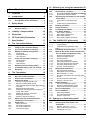 3
3
-
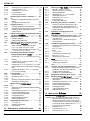 4
4
-
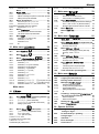 5
5
-
 6
6
-
 7
7
-
 8
8
-
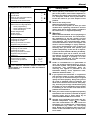 9
9
-
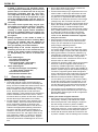 10
10
-
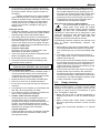 11
11
-
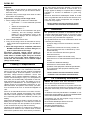 12
12
-
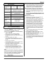 13
13
-
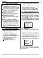 14
14
-
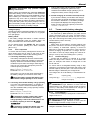 15
15
-
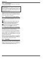 16
16
-
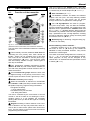 17
17
-
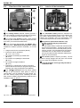 18
18
-
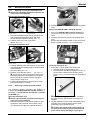 19
19
-
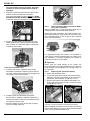 20
20
-
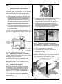 21
21
-
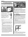 22
22
-
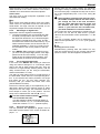 23
23
-
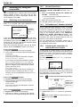 24
24
-
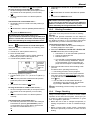 25
25
-
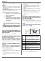 26
26
-
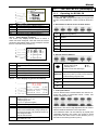 27
27
-
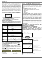 28
28
-
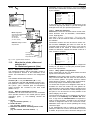 29
29
-
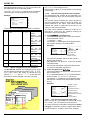 30
30
-
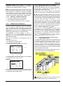 31
31
-
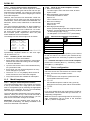 32
32
-
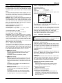 33
33
-
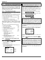 34
34
-
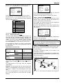 35
35
-
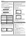 36
36
-
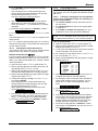 37
37
-
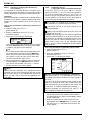 38
38
-
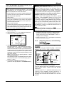 39
39
-
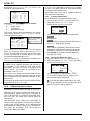 40
40
-
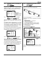 41
41
-
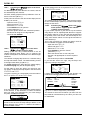 42
42
-
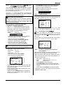 43
43
-
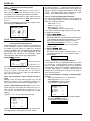 44
44
-
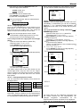 45
45
-
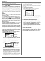 46
46
-
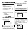 47
47
-
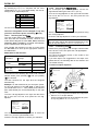 48
48
-
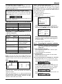 49
49
-
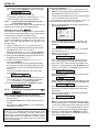 50
50
-
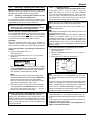 51
51
-
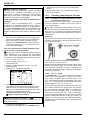 52
52
-
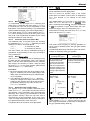 53
53
-
 54
54
-
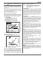 55
55
-
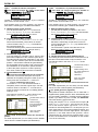 56
56
-
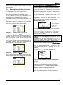 57
57
-
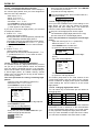 58
58
-
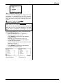 59
59
-
 60
60
-
 61
61
-
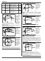 62
62
-
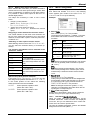 63
63
-
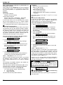 64
64
-
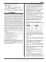 65
65
-
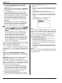 66
66
-
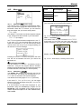 67
67
-
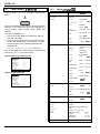 68
68
-
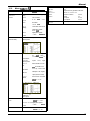 69
69
-
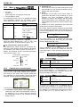 70
70
-
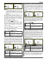 71
71
-
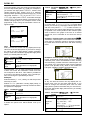 72
72
-
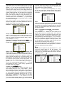 73
73
-
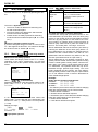 74
74
-
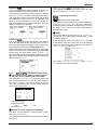 75
75
-
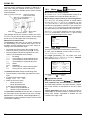 76
76
-
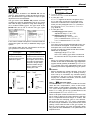 77
77
-
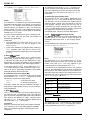 78
78
-
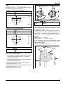 79
79
-
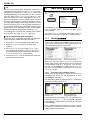 80
80
-
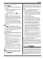 81
81
-
 82
82
-
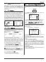 83
83
-
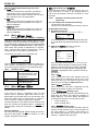 84
84
-
 85
85
-
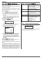 86
86
-
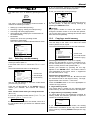 87
87
-
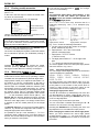 88
88
-
 89
89
-
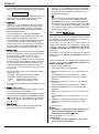 90
90
-
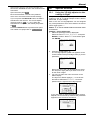 91
91
-
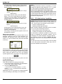 92
92
-
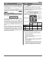 93
93
-
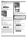 94
94
-
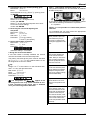 95
95
-
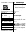 96
96
-
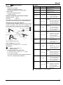 97
97
-
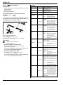 98
98
-
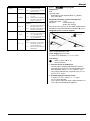 99
99
-
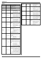 100
100
-
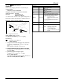 101
101
-
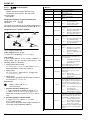 102
102
-
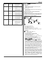 103
103
-
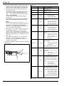 104
104
-
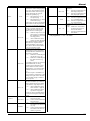 105
105
-
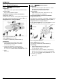 106
106
-
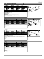 107
107
-
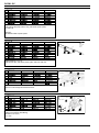 108
108
-
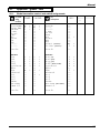 109
109
-
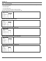 110
110
-
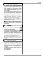 111
111
-
 112
112
-
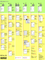 113
113


MULTIPLEX Royal Sx 16 Elegance Manuale del proprietario
- Categoria
- Giocattoli
- Tipo
- Manuale del proprietario
in altre lingue
Documenti correlati
-
MULTIPLEX Royal Evo 7 Manuale del proprietario
-
-
Hitec RCD IFHHFM-4-72 Manuale utente
-
-
-
Hitec RCD IFHHFMS-CAR-75 Manuale utente
-
Altri documenti
-
BNF BLH3100 Manuale utente
-
Blade SR Manuale utente
-
Align HEGBP301 Manuale del proprietario
-
-
Spektrum SPM8800C Manuale del proprietario
-
 Multiplex Technology COCKPIT SX Istruzioni per l'uso
-
Spektrum DX8 Transmitter Only Mode 2 Manuale utente
-
Snap-On TECHANGLE Manuale utente
-
Digi DC-ES-8SB Guida d'installazione
-
Digi Connect W Manuale utente
