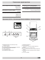
Indesit K6G21(B)/R Guida utente
- Categoria
- Barbecue
- Tipo
- Guida utente
Questo manuale è adatto anche per

Cucina
Installazione e uso
Cooker
Installation and use
Êóõoííaÿ ïëèòà
Óñòàíîâêà è ïîëüçîâàíèå
Konyhabútor
Beépítés és használat
Aragaz
Instalare ºi utilizare
Ãîòâàðñêà ïå÷êà
Ìîíòàæ è óïîòðåáà
K6G21/R
K6G21S/R

Cucina con forno gas e grill gas
Istruzioni per l'installazione e l'uso 3
Cooker with gas oven and gas grill
Instructions for installation and use 13
Ïëèòà ñ ãàçîâîé äóõîâêîé è ãàçîâûì ãðèëåì
Èíñòðóêöèè ïî óñòàíîâêå è ýêñïëóàòàöèè 23
Gáz sütõvel és gáz grillel rendelkezõ tûzhely
Használati útmutató 35
Aragaz cu cuptor pe gaz ºi grill pe gaz
Instrucþiuni pentru instalare ºi utilizare 46
Ãîòâàðñêà ïå÷êà ñ ôóðíà è ãðèë íà ãàç
Èíñòðóêöèÿ çà ìîíòàæ è óïîòðåáà
56

3
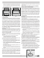
1 Queste istruzioni sono valide solo per i paesi di destinazio-
ne i cui simboli figurano sul libretto e sulla targa matricola
dell’apparecchio.
2 Questo apparecchio è stato concepito per un uso di tipo
non professionale all'interno di abitazione.
3 Prima di utilizzare l'apparecchio, leggere attentamente le
avvertenze contenute nel presente libretto in quanto forni-
scono importanti indicazioni riguardanti la sicurezza di in-
stallazione, d’uso e di manutenzione. Conservare con cura
questo libretto per ogni ulteriore consultazione.
4 Dopo aver tolto l’imballaggio assicurarsi dell’integrità dell’appa-
recchio. In caso di dubbio non utilizzare l’apparecchio e rivolgersi
a personale professionalmente qualificato. Gli elementi dell’imbal-
laggio (sacchetti in plastica, polistirolo espanso, chiodi, ecc.) non
devono essere lasciati alla portata dei bambini in quanto poten-
ziali fonti di pericolo.
5 L’installazione deve essere effettuata secondo le istruzioni del
costruttore da personale professionalmente qualificato. Una er-
rata installazione può causare danni a persone, animali o cose,
nei confronti dei quali il costruttore non può essere considerato
responsabile.
6 La sicurezza elettrica di questo apparecchio è assicurata soltan-
to quando lo stesso è correttamente collegato ad un efficiente
impianto di messa a terra come previsto dalle vigenti norme di
sicurezza elettrica. E’ necessario verificare questo fondamentale
requisito di sicurezza e, in caso di dubbio, richiedere un controllo
accurato dell’impianto da parte di personale professionalmente
qualificato. Il costruttore non può essere considerato responsa-
bile per eventuali danni causati dalla mancanza di messa a terra
dell’impianto.
7 Prima di collegare l’apparecchio accertarsi che i dati di targa
siano rispondenti a quelli della rete di distribuzione elettrica e gas.
8 Verificare che la portata elettrica dell’impianto e delle prese di
corrente siano adeguate alla potenza massima dell’apparecchio
indicata in targa. In caso di dubbio rivolgersi ad una persona
professionalmente qualificata.
9 All’installazione occorre prevedere un interruttore omnipolare con
distanza di apertura dei contatti uguale o superiore a 3 mm.
10 In caso di incompatibilità tra la presa e la spina dell’apparecchio
fare sostituire la presa con altra di tipo adatto da personale pro-
fessionalmente qualificato. Quest’ultimo, in particolare, dovrà an-
che accertare che la sezione dei cavi della presa sia idonea alla
potenza assorbita dall’apparecchio. In generale è sconsigliabile
l’uso di adattatori, prese multiple e/o prolunghe. Qualora il loro uso
si rendesse indispensabile è necessario utilizzare solamente adat-
tatori semplici o multipli e prolunghe conformi alle vigenti norme di
sicurezza, facendo però attenzione a non superare il limite di
portata in valore di corrente, marcato sull’adattatore semplice e
sulle prolunghe, e quello di massima potenza marcato sull’adatta-
tore multiplo.
11 Non lasciare l’apparecchio inutilmente inserito. Spegnere l’inter-
ruttore generale dell’apparecchio quando lo stesso non è utilizza-
to, e chiudere il rubinetto del gas.
12 Non ostruire le aperture o fessure di ventilazione o di smaltimento
calore.
13 Il cavo di alimentazione di questo apparecchio non deve essere
sostituito dall’utente. In caso di danneggiamento del cavo, o per la
sua sostituzione, rivolgersi esclusivamente ad un centro di assi-
stenza tecnica autorizzato dal costruttore.
14 Questo apparecchio dovrà essere destinato solo all’uso per il
quale è stato espressamente concepito. Ogni altro uso (ad esem-
pio: riscaldamento di ambienti) è da considerarsi improprio e quin-
di pericoloso. Il costruttore non può essere considerato respon-
sabile per eventuali danni derivanti da usi impropri, erronei ed
irragionevoli.
15 L’uso di un qualsiasi apparecchio elettrico comporta l’osservanza
di alcune regole fondamentali. In particolare:
· non toccare l’apparecchio con mani o piedi bagnati o umidi
· non usare l’apparecchio a piedi nudi
· non usare, se non con particolare cautela, prolunghe
· non tirare il cavo di alimentazione, o l’apparecchio stesso,
per staccare la spina dalla presa di corrente.
· non lasciare esposto l’apparecchio ad agenti atmosferici (piog-
gia, sole, ecc.)
· non permettere che l’apparecchio sia usato dai bambini o da
incapaci, senza sorveglianza
16 Prima di effettuare qualsiasi operazione di pulizia o di manuten-
zione, disinserire l’apparecchio dalla rete di alimentazione elettri-
ca, o staccando la spina, o spegnendo l’interruttore dell’impianto.
17 Allorchè si decida di non utilizzare più di un apparecchio di questo
tipo, si raccomanda di renderlo inoperante tagliandone il cavo di
alimentazione, dopo aver staccato la spina dalla presa di corren-
te. Si raccomanda inoltre di rendere innocue quelle parti dell’ap-
parecchio suscettibili di costituire un pericolo, specialmente per i
bambini che potrebbero servirsi dell’apparecchio fuori uso per i
propri giochi.
18 Sui bruciatori e sulle piastre elettriche non debbono essere poste
pentole instabili o deformate onde evitare incidenti per rovescia-
mento.
19 Non lasciate le piastre di cottura accese senza pentole, in quanto
si avrebbe un riscaldamento massimo in poco tempo, con possi-
bili danni dell’apparecchio o dei mobili circostanti.
20 Alcune parti dell’apparecchio, in particolare le piastre elettriche,
rimangono calde per lungo tempo dopo l’uso. Fate attenzione a
non toccarle.
21 Non utilizzate liquidi infiammabili (alcool, benzina...) in vicinanza
all’apparecchio mentre questo è in uso.
22 Usando piccoli elettrodomestici nelle vicinanze del piano fate at-
tenzione che il cavo di alimentazione non finisca su parti calde
23 Controllare sempre che le manopole siano nella posizione “·”/“
¡
”
quando l’apparecchio non è utilizzato.
24
Durante l'uso dell'apparecchio gli elementi riscaldanti e al-
cune parti della porta forno diventano molto calde. Fare
attenzione a non toccarle e tenere i bambimi a distanza.
25 Gli apparecchi gas necessitano, per un corretto funziona-
mento, di un regolare ricambio d’aria. Accertarsi che nella
loro installazione siano rispettati i requisiti richiesti nel pa-
ragrafo relativo al “Posizionamento”.
26 Se la cucina viene posta su di un piedistallo, prendere adeguati
accorgimenti affinchè l'apparecchio non scivoli dal piedistallo stes-
so.
27 Attenzione: non utilizzare mai il vano inferiore per il deposito di
materiale infiammabile.
28 Questo apparecchio riguarda un apparecchio di classe 1
(isolato) o classe 2 - sottoclasse 1 (incassato tra 2 mobili).
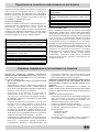
Avvertenze
Per garantire l’efficienza e la sicurezza di questo elettrodomestico:
• rivolgetevi esclusivamente a centri di assistenza tecnica autorizzati
• richiedete sempre l’utilizzo di parti di ricambio originali

4
Istruzioni per l’installazione
Le istruzioni che seguono sono rivolte all’installatore qualifi-
cato affinchè compia le operazioni di installazione regolazione
e manutenzione tecnica nel modo più corretto e secondo le
norme in vigore.
Importante: qualsiasi intervento di regolazione, manu-
tenzione etc. deve essere eseguito con la cucina elettri-
camente disinserita.
Posizionamento
Importante: questo apparecchio può essere installato e fun-
zionare solo in locali permanentemente ventilati secondo le
prescrizioni delle Norme UNI-CIG 7129 e 7131 in vigore. Deb-
bono essere osservati i seguenti requisiti:
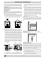
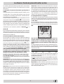
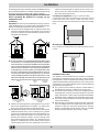
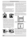
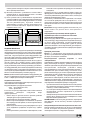
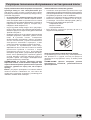
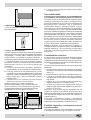
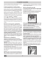
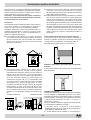
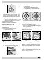
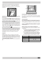
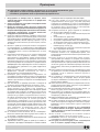
a) Il locale deve prevedere un sistema di scarico all’esterno
dei fumi della combustione, realizzato tramite una cappa
o tramite un elettroventilatore che entri automaticamente
in funzione ogni volta che si accende l’apparecchio.
In camino o in canna fumaria ramificata Direttamente all’esterno
(riservata agli apparecchi di cottura)
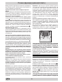
b) Il locale deve prevedere un sistema che consenta l’af-
flusso dell’aria necessaria alla regolare combustione. La
portata di aria necessaria alla combustione non deve es-
sere inferiore a 2 m
3
/h per kW di potenza installata. Il
sistema può essere realizzato prelevando direttamente
l’aria dall’esterno dell’edificio tramite un condotto di alme-
no 100 cm
2
di sezione utile e tale che non possa essere
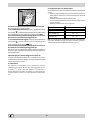
accidentalmente ostruito. Per gli apparecchi privi sul pia-
no di lavoro, del dispositivo di sicurezza per assenza di
fiamma, le aperture di ventilazione debbono essere mag-
giorate nella misura del 100%, con un minimo di 200 cm
2
(Fig. A). Ovvero, in maniera indiretta da locali adiacenti,
dotati di un condotto di ventilazione con l’esterno come
sopra descritto, e che non siano parti comuni dell’immo-
bile, o ambienti con pericolo di incendio, o camere da
letto (Fig. B).
Particolare A Locale Locale da
adiacente ventilare
A
Esempi di aperture di ventilazione Maggiorazione della fessura fra
per l’aria comburente porta e pavimento
Fig. A Fig. B
c) Un utilizzo intensivo e prolungato dell’apparecchio può
necessitare di una aerazione supplementare per esem-
pio l’apertura di una finestra o una aerazione più efficace
aumentando la potenza di spirazione meccanica se essa
esiste.
d) I gas di petrolio liquefatti, più pesanti dell’aria, ristagnano
verso il basso. Quindi i locali contenenti bidoni di GPL
debbono prevedere delle aperture verso l’esterno così da
permettere l’evacuazione dal basso delle eventuali fughe
di gas. Pertanto i bidoni di GPL, siano essi vuoti o parzial-
mente pieni, non debbono essere installati o depositati in
locali o vani a livello più basso del suolo (cantinati, ecc.).
É opportuno tenere nel locale solo il bidone in utilizzo,
collocato in modo da non essere soggetto all’azione diret-
ta di sorgenti di calore (forni, camini, stufe, ecc.) capaci
di portarlo a temperature superiori ai 50°C.
Livellamento (presente solo su alcuni modelli)
Nella parte inferiore dell’apparecchio si trovano 4 piedini di
sostegno regolabili con viti che permettono di migliorare il
livellamento dell’apparecchio, se necessario. E’ indispen-
sabile che l’apparecchio sia posizionato in modo unifor-
me.
Montaggio gambe (presente solo su alcuni modelli)
Vengono fornite delle gambe da montare ad incastro sotto
la base della cucina.
Installazione della cucina
E' possibile l’installazione a fianco di mobili la cui altezza non
superi quella del piano di lavoro. La parete a contatto con la
parete posteriore della cucina deve essere in materiale
ininfiammabile. Durante il funzionamento la parete posteriore
della cucina può raggiungere una temperatura di 50°C supe-
riore a quella ambiente. Per una corretta installazione della
cucina vanno osservate le seguenti precauzioni:
a) I mobili situati a fianco, la cui altezza superi quella del
piano di lavoro, debbono essere situati ad almeno 600
mm dal bordo del piano stesso.
b) Le cappe debbono essere installate secondo i requisiti
richiesti nei libretti istruzioni delle cappe stesse e comun-
que ad una distanza minima di 650 mm.
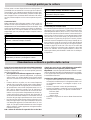
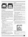
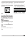
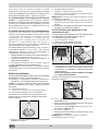
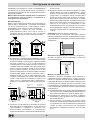
c) Allorchè la cucina venga installata sotto un pensile, que-

5
st’ultimo dovrà mantenere una distanza minima dal piano
di 700 mm (millimetri). I mobili adiacenti alla cappa do-
vranno mantenere una distanza minima dal piano di 420
mm. come da Fig. C e D.
HOOD
420
Min.
min.
650
mm. with hood
min.
700
mm. without hood
mm.
600
Min. mm.
420
Min. mm.
HOOD
900
Min. mm.
420
Min.
min.
650
mm. with hood
min.
700
mm. without hood
mm.
420
Min. mm.
Fig. C Fig. D
Collegamento gas
Il collegamento dell’apparecchio alla tubazione o alla bombo-
la del gas dovrà essere effettuato come prescritto dalle Nor-
me UNI-CIG 7129 e 7131, solo dopo essersi accertati che
esso è regolato per il tipo di gas con cui sarà alimentato. In
caso contrario eseguire le operazioni indicate al paragrafo
“Adattamento ai diversi tipi di gas”. Su alcuni modelli l’ali-
mentazione del gas può avvenire indifferentemente da de-
stra o da sinistra a seconda dei casi; per cambiare il collega-
mento è necessario invertire il portagomma con il tappo di
chiusura e sostituire la guarnizione di tenuta (in dotazione
con l’apparecchio). Nel caso di alimentazione con gas liqui-
do, da bombola, utilizzare regolatori di pressione conformi
alle Norme UNI-CIG 7432.
Importante: per un sicuro funzionamento, per un adeguato
uso dell’energia e maggiore durata dell’apparecchiatura, as-
sicurarsi che la pressione di alimentazione rispetti i valori
indicati nella tabella 1 “Caratteristiche dei bruciatori ed ugelli”.
Allaccio con tubo flessibile
Eseguire il collegamento per mezzo di un tubo flessibile per
gas rispondente alle caratteristiche indicate nelle norme UNI-
CIG 7140.
Il diametro interno del tubo da utilizzare deve essere:
- 8mm per alimentazione con gas liquido;
- 13mm per alimentazione con gas metano.
In particolare, per la messa in opera di tali tubi flessibili, deb-
bono essere rispettate le seguenti prescrizioni:
• Non deve essere in nessun punto del suo percorso a con-
tatto con parti che siano a temperature maggiori di 50°C;
• Abbia una lunghezza inferiore a 1500 mm;
• Non sia soggetto ad alcun sforzo di trazione e di torsione,
inoltre non deve presentare curve eccessivamente stret-
te o strozzature;
• Non venga a contatto con corpi taglienti, spigoli vivi e con
parti mobili o schiacciato;
• Deve essere facilmente ispezionabile lungo tutto il per-
corso allo scopo di poter controllare il suo stato di conser-
vazione;
Assicurarsi che il tubo sia ben calzato alle sue due estremità
e fissarlo per mezzo di fascette di serraggio conformi alla
UNI-CIG 7141. Qualora una o più di queste condizioni non
possa essere rispettata, bisognerà ricorrere ai tubi metallici
flessibili, conformi alla norma UNI-CIG 9891.
Allorchè la cucina venga installata secondo le condizioni della
classe 2 sottoclasse 1 è opportuno collegarsi alla rete gas
solamente tramite tubo metallico flessibile conforme alla
UNI-CIG 9891.
Allaccio con tubo flessibile in acciaio inossidabile a
parete continua con attacchi filettati
Eliminare il portagomma già presente sull’apparecchio. Il rac-
cordo di entrata del gas all’apparecchio è filettato 1/2 gas
maschio cilindrico. Utilizzare esclusivamente tubi conformi
alla Norma UNI-CIG 9891 e guarnizioni di tenuta conformi
alla UNI-CIG 9264. La messa in opera di tali tubi deve essere
effettuata in modo che la loro lunghezza, in condizioni di
massima estensione, non sia maggiore di 2000 mm. Ad al-
lacciamento avvenuto assicurarsi che il tubo metallico fles-
sibile non venga a contatto con parti mobili o schiacciato.
Controllo tenuta
Importante: ad installazione ultimata controllare la perfetta
tenuta di tutti i raccordi utilizzando una soluzione saponosa
e mai una fiamma.
Allacciamento del cavo di alimentazione alla rete
Montare sul cavo una spina normalizzata per il carico indica-
to sulla targhetta caratteristiche, nel caso di collegamento
diretto alla rete è necessario interporre tra l’apparecchio e la
rete un interruttore omnipolare con apertura minima fra i con-
tatti di 3 mm. dimensionato al carico e rispondente alle nor-
me in vigore (il filo di terra non deve essere interrotto dall’in-
terruttore). Il cavo di alimentazione deve essere posizionato
in modo che non raggiunga in nessun punto una temperatura
superiore di 50°C a quella ambiente. Prima di effettuare l’al-
lacciamento accertarsi che:
• la valvola limitatrice e l’impianto domestico possano sop-
portare il carico dell’apparecchiatura (vedi targhetta ca-
ratteristiche);
• l’impianto di alimentazone sia munito di efficace collega-
mento a terra secondo le norme e le disposizioni di legge;
• la presa o l’interruttore omnipolare siano facilmente
raggiungibili con il piano installato.
N.B: non utilizzare riduzioni, adattatori o derivatori in quanto
essi potrebbero provocare riscaldamenti o bruciature.
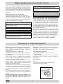
Adattamento del piano ai diversi tipi di gas
Per adattare la cucina ad un tipo di gas diverso da quello per
il quale essa è predisposta (indicato sulla etichetta fissata al
coperchio), occorre effettuare le seguenti operazioni:
a) Sostituire il portagomma già montato con quello contenu-
to nella confezione “accessori della cucina”.
Attenzione: Il portagomma per gas liquido porta stampigliato
il numero 8, quello per gas metano il numero 13). Avvalersi
comunque di una guarnizione di tenuta nuova.
b) Sostituzione degli ugelli dei bruciatori del piano:
• togliere le griglie e sfilare i bruciatori dalle loro sedi;
• svitare gli ugelli, servendosi di una chiave a tubo da 7
mm, e sostituirli con quelli adatti al nuovo tipo di gas
(vedi tabella 1 “Caratteristiche dei bruciatori ed ugelli”).
• rimettere in posizione tutti i componenti seguendo le ope-
razioni inverse rispetto alla sequenza di cui sopra.

6
c) Regolazione minimi dei bruciatori del piano:
• portare il rubinetto sulla posizione di minimo;
• togliere la manopola ed agire sulla vite di regolazione po-
sta all’interno o di fianco all’astina del rubinetto fino ad
ottenere una piccola fiamma regolare.
N.B.: nel caso dei gas liquidi, la vite di regolazione dovrà
essere avvitata a fondo.
• verificare poi che ruotando rapidamente il rubinetto dalla
posizione di massimo a quella di minimo, non si abbiano
spegnimenti del bruciatore.
d) Regolazione aria primaria dei bruciatori del piano:
I bruciatori non necessitano di alcuna regolazione dell’aria
primaria.
Adattamento ai diversi tipi di gas
Per adattare il forno ad un tipo di gas diverso da quello per
il quale esso è predisposto (indicato sull’ etichetta), occor-
re effettuare le seguenti operazioni:
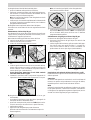
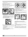
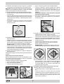
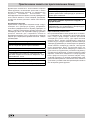
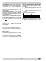
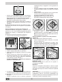
a) Sostituzione dell’ugello del bruciatore del forno
· aprire la porta del forno completamente
· estrarre il fondo forno scorrevole
· svitare la vite di fissaggio del bruciatore
V
· rimuovere il bruciatore del forno dopo aver tolto la vite
“V”;
· svitare l’ugello del bruciatore forno servendosi dell’ap-
posita chiave a tubo per ugelli, o meglio ancora di una
chiave a tubo di 7 mm e sostituirlo con quello adatto al
nuovo tipo di gas (vedi tabella 1).
Porre particolare attenzione ai cavi delle candele
ed ai tubi delle termocoppie.
· rimettere in posizione tutti i componenti seguendo le
operazioni inverse rispetto alla sequenza di cui sopra.
b) Regolazione del minimo del bruciatore forno gas
termostatato:
• accendere il bruciatore come descritto al paragrafo “la
manopola del forno” del libretto d’uso;
• portare la manopola sulla posizione di Min dopo aver la-
sciato la stessa per 10 minuti circa in posizione Max;
• togliere la manopola;
• agire sulla vite di regolazione posta all’esterno
dell’astina del termostato fino ad ottenere una piccola
fiamma regolare;
N.B.: nel caso dei gas liquidi, la vite di regolazione
dovrà essere avvitata a fondo.
• verificare poi che ruotando rapidamente la manopola dal-
la posizione Max alla posizione di Min o con rapide aper-
ture e chiusure della porta del forno non si abbiano
spegnimenti del bruciatore.
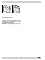
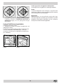
Adattamento del grill gas ai diversi tipi di gas
Sostituzione dell’ugello del bruciatore del grill:
• rimuovere il bruciatore del grill dopo aver tolto la vite
“V” (vedi Fig. E);
• svitare l’ugello del bruciatore grill servendosi dell’appo-
sita chiave a tubo per ugelli (vedi Fig. F), o meglio an-
cora di una chiave a tubo di 7 mm e sostituirlo con
quello adatto al nuovo tipo di gas (vedi tabella 1).
V
I
Fig. E Fig. F
Regolazione aria primaria del bruciatore forno e grill
Il bruciatore forno e grill non necessitano di alcuna regolazione
dell’aria primaria.
Attenzione
Al termine dell’operazione sostituire la vecchia etichetta di
taratura con quella corrispondente al nuovo gas di utilizzo,
reperibile presso i nostri Centri Assistenza Tecnica.
Nota
Qualora la pressione del gas utilizzato sia diversa (o variabi-
le) da quella prevista, è necessario installare, sulla tubazio-
ne d’ingresso un appropriato regolatore di pressione (secon-
do UNI-CIG 7430 “regolatori per gas canalizzati”).

7
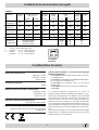
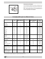
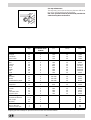
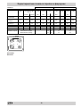
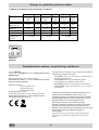
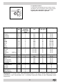
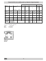
Caratteristiche dei bruciatori ed ugelli
Tabella 1 Gas liquido Gas naturale
Bruciatore Diametro
(mm)
Potenza termica
kW (p.c.s.*)
By-pass
1/100
Ugello
1/100
Portata*
g/h
Ugello
1/100
Portata*
l/h
Nomin. Ridot. (mm) (mm) *** ** (mm)
Rapido
(Grande) (R)
100 3,00 0,7 41 86 218 214 116 286
Semi Rapido
(Medio) (S)
75 1,90 0,4 30 70 138 136 106 181
Ausiliario
(Piccolo) (A)
55 1,00 0,4 30 50 73 71 79 95
Forno - 2,60 1,0 52 78 189 186 119 248
Grill - 2,50 - - 80 182 179 122 238
Pressioni di
alimentazione
Nominale (mbar)
Minima (mbar)
Massima (mbar)
28-30
20
35
37
25
45
20
17
25
* A 15°C e 1013 mbar-gaz secco
** Propano P.C.S. = 50,37 MJ/Kg
*** Butano P.C.S. = 49,47 MJ/Kg
Naturale P.C.S. = 37,78 MJ/m
3
S
S
R
A
K6 G21S/R
K6 G21/R
Dimensioni utili del forno:
larghezza cm 43.5
profondità cm 43.5
altezza cm 31
Volume utile del forno:
litri 58
Dimensioni utili del cassetto scaldavivande:
larghezza cm. 46
profondità cm. 42
altezza cm. 8.5
Tensione e frequenza di alimentazione:
vedi targhetta caratteristiche
Bruciatori:
adattabili a tutti i tipi di gas indicati nella targhetta
caratteristiche
Questa apparecchiatura è conforme alle seguenti
Direttive Comunitarie:
- 73/23/CEE del 19/02/73 (Bassa Tensione) e successi-
ve modificazioni;
- 89/336/CEE del 03/05/89 (Compatibilità Elettromagne-
tica) e successive modificazioni;
- 90/396/CEE del 29/06/90 (Gas) e successive
modificazioni;
- 93/68/CEE del 22/07/93 e successive modificazioni.
- 2002/96/CE
La direttiva Europea 2002/96/CE sui rifiuti di
apparecchiature elettriche ed elettroniche (RAEE), preve-
de che gli elettrodomestici non debbano essere smaltiti
nel normale flusso dei rifiuti solidi urbani. Gli apparecchi
dismessi devono essere raccolti separatamente per
ottimizzare il tasso di recupero e riciclaggio dei materiali
che li compongono ed impedire potenziali danni per la sa-
lute e l’ambiente. Il simbolo del cestino barrato è riportato
su tutti i prodotti per ricordare gli obblighi di raccolta sepa-
rata.
Per ulteriori informazioni, sulla corretta dismissione degli
elettrodomestici, i detentori potranno rivolgersi al servizio
pubblico preposto o ai rivenditori.
Caratteristiche Tecniche

8
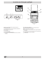
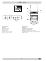
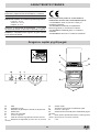
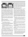
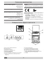
La cucina con forno gas e grill gas
A Piano di contenimento eventuali trabocchi
B Bruciatore a gas
C Dispositivo di accensione istantanea elettronica
D Griglia del piano di lavoro
E Cruscotto
F Piedini regolabili
G Leccarda o piatto di cottura
J Dispositivo di sicurezza (presente solo su alcuni
modelli)
K Griglia ripiano del forno
L Accensione elettronica dei bruciatori del piano
M Manopola del forno e del grill
N Manopole di comando dei bruciatori a gas del piano
di cottura
O Pulsante per accensione della luce forno e girarrosto
(presente solo su alcuni modelli)
P Contaminuti
C
J
M
P L
O
N
F
A
E
K
G
D
B

9
Le diverse funzioni presenti nella cucina
La selezione delle varie funzioni presenti nella cucina avviene
agendo sui dispositivi ed organi di comando posti sul cruscotto
della stessa.
Le manopole di comando dei bruciatori a gas del piano di
cottura
In corrispondenza di ciascuna delle manopole è indicata, con un
cerchietto pieno
•, la posizione del bruciatore a gas da essa
comandato. Per accendere uno dei bruciatori, avvicinare allo stes-
so una fiamma o un accenditore.
Premere a fondo e ruotare la manopola corrispondente in senso
antiorario fino alla posizione di massimo
E
.Ciascun bruciatore
può funzionare al massimo della sua potenza, al minimo, o con
potenze intermedie. In relazione a queste diverse prestazioni,
sulla manopola, oltre alla posizione di spento, individuata dal
simbolo
• quando questo à posto in corrispondenza della tacca
di riferimento, sono indicate le posizioni di massimo
E
e di
minimo
C
.
Esse si ottengono facendo ruotare la manopola in senso antiorario
dalla posizione di spento.Per spegnere il bruciatore occorre inve-
ce ruotare la manopola in senso orario fino all’arresto (corrispon-
dente di nuovo al simbolo
•).
Accensione elettronica dei bruciatori del piano
Alcuni modelli sono dotati di accensione istantanea elettronica
dei bruciatori a gas del piano di cottura: essi sono riconoscibili
per la presenza del dispositivo di accensione (vedi dettaglio C).
Questo dispositivo entra in funzione esercitando una leggera
pressione sul pulsante “L” identificato dal simbolo
1
. Per ac-
cendere il bruciatore prescelto è perciò sufficiente premere il
pulsante “L” e contemporaneamente premere a fondo e ruotare in
senso antiorario la manopola corrispondente fino all’avvenuta
accensione. Per un’accensione immediata è consigliabile
prima premere il pulsante poi ruotare la manopola.
Avvertenza: nel caso di una estinzione accidentale delle fiam-
me del bruciatore, chiudere la manopola di comando e non
ritentare l’accensione se non dopo almeno 1 minuto.
Modelli con dispositivo di sicurezza contro fughe di gas
per i bruciatori del piano (presente solo su alcuni modelli)
Potete identificare questi modelli per la presenza del dispositivo
(Vedi dettaglio J).
Importante: dato che i bruciatori del piano sono dotati di disposi-
tivo di sicurezza, dopo l’accensione del bruciatore, è necessa-
rio mantenere premuta la manopola per circa 3 secondi in
modo da consentire il passaggio del gas finché non si scalda la
termocoppia di sicurezza.
Attenzione: Alla prima accensione consigliamo di far fun-
zionare il forno a vuoto per circa mezz'ora con il termosta-
to al massimo e a porta chiusa. Quindi trascorso tale tem-
po spegnerlo, aprite la porta ed areare il locale. L'odore
che talvolta si avverte durante questa operazione è dovu-
to all'evaporazione delle sostanze usate per proteggere il
forno durante l'intervallo di tempo che intercorre tra la pro-
duzione e l'installazione del prodotto.
Attenzione: Utilizzare il primo ripiano dal basso solamen-
te nel caso di cotture con girarrosto (ove presente). Per le
altre cotture non utilizzate mai il primo ripiano dal basso e
non appoggiate mai oggetti sul fondo del forno mentre sta-
te cuocendo perchè potreste causare danni allo smalto.
Ponete sempre i Vostri recipienti di cottura (pirofile, pelli-
cole di alluminio, ecc. ecc.) sulla griglia in dotazione con
l’apparecchio appositamente inserita nelle guide del forno.
La manopola del forno e del grill (M)
E’ il dispositivo che permette di selezionare le diverse funzioni
del forno e di scegliere la temperatura di cottura più idonea ai cibi
da cuocere fra quelle indicate sulla manopola stessa (comprese
fra Min e Max).
Per accendere il bruciatore forno, avvicinare al foro “F” una fiam-
ma o un accenditore, contemporaneamente premere a fondo e
ruotare la manopola forno in senso antiorario fino alla posizione
Max.
F
Dato che il forno è dotato di dispositivo di sicurezza è ne-
cessario mantenere premuta la manopola per circa 4 se-
condi in modo da consentire il passaggio del gas. (Per i
modelli dotati di accensione elettronica vedi il relativo para-
grafo).
La selezione della temperatura di cottura si ottiene facendo cor-
rispondere l’indicazione del valore desiderato con il riferimento
posto sul cruscotto; la gamma completa delle temperature ottenibili
è riportata qui sotto.
Min • 160 • 180 • 220 Max
150 155 170 200 250
La temperatura impostata viene automaticamente raggiunta e
mantenuta costante dall’organo di controllo (il termostato) co-
mandato dalla manopola.
Premendo a fondo e ruotando la manopola “M” fino alla posizio-
ne
si mette in funzione il grill a raggi infrarossi, che permet-
te la doratura dei cibi oltre ad essere consigliato per la cottura di
arrosti (braciole, salsicce, roast-beef).
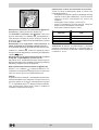
Importante: quando si utilizza il grill è necessario lasciare
la porta del forno semiaperta posizionando fra porta e cru-
scotto il deflettore “D” che impedisce il surriscaldamento
delle manopole della cucina.

10
D
Accensione elettronica del bruciatori del forno e del grill
(L) (presente solo su alcuni modelli)
Per accendere il bruciatore forno premere il pulsante identificato
con il simbolo
1
, contemporaneamente premere a fondo e ruotare
la manopola forno in senso antiorario fino alla posizione Max.
E' necessario tenere premuta la manopola per circa 4 secon-
di in modo da consentire il passaggio del gas.
Per accendere il bruciatore grill premere il pulsante identificato
con il simbolo
1
, premere a fondo e ruotare la manopola forno in
senso orario fino alla posizione
(grill).
E' necessario tenere premuta la manopola per circa 4 secon-
di in modo da consentire il passaggio del gas.
Nel caso di mancanza di elettricità potete accendere manualmen-
te il forno o il grill seguendo le istruzioni riportate nel paragrafo "La
manopola del forno".
Il pulsante per l’accensione della luce del forno (O)
E’ quello individuato dal simbolo
I
e consente con l’accensio-
ne della lampada all’interno del forno, di seguire l’andamento della
cottura senza aprire la porta.
Il contaminuti
Per utilizzare il contaminuti occorre caricare la suoneria
ruotando la manopola “P”di un giro quasi completo in sen-
so orario
4; quindi, tornando indietro 5, impostare il
tempo desiderato facendo coincidere con il riferimento fis-
so del frontalino il numero corrispondente ai minuti prefis-
sati.
Consigli pratici per l’uso dei bruciatori
Al fine di ottenere il massimo rendimento è utile ricordare quanto
segue:
• utilizzare recipienti adeguati a ciascun bruciatore (vedere ta-
bella) alfine di evitare che le fiamme fuoriescano dal fondo
dei recipienti.
• utilizzare solamente recipienti a fondo piatto.
• al momento dell’ebollizione ruotare la manopola fino alla po-
sizione di minimo.
• utilizzare sempre recipienti con coperchio.
Bruciatore ø Diametro recipienti (cm)
Rapido (R) 24 – 26
Semi Rapido (S) 16 – 20
Ausiliario (A) 10 – 14
N.B. Sui modelli dotati di griglietta di riduzione, quest’ultima do-
vrà essere utilizzata solo per il bruciatore ausiliario, quando si
utilizzano dei recipienti di diametro inferiore a 12 cm.

11
Consigli pratici per la cottura
Il forno mette a vostra disposizione una vasta gamma di
possibilità che consentono di cuocere ogni cibo nella ma-
niera migliore. Con il tempo potrete sfruttare al meglio que-
sto versatile apparecchio di cottura, pertanto le note ripor-
tate di seguito sono solamente delle indicazioni di massi-
ma che potrete ampliare con la vostra esperienza perso-
nale.
Cottura dei dolci
Nella cottura dei dolci infornate sempre a forno caldo, at-
tendete la fine di preriscaldamento, (circa 15 minuti). Le
temperature sono normalmente nell’intorno di 160°C. Non
aprite la porta durante la cottura, per evitare un abbassa-
mento del dolce. Gli impasti sbattuti non devono essere
troppo fluidi, per non prolungare troppo i tempi di cottura.
In generale:
Dolce troppo secco
La prossima volta impostate una temperatura di10°C
superiore e riducete il tempo di cottura.
Dolce si abbassa
Usate meno liquido o abbassate la temperatura di
10°C.
Dolce scuro superiormente
Inseritelo ad altezza inferiore, impostate una
temperatura più bassa e prolungate la cottura.
Buona cottura esterna, ma interno colloso
Usate meno liquido, riducete la temperatura,
aumentate il tempo di cottura.
Dolce non si stacca dallo stampo
Ungete bene lo stampo e cospargetelo anche con un
pò di farina.
Cottura del pesce e della carne
La carne deve pesare almeno 1 Kg. per evitare che si asciu-
ghi troppo. Per le carni bianche, i volatili ed il pesce utiliz-
zate temperature basse (150°C-175°C). Per le carni rosse
che si vuole siano ben cotte all’esterno conservando all’in-
terno il sugo, è bene iniziare con una temperatura iniziale
alta (200-220°C) per breve tempo, per poi diminuirla suc-
cessivamente. In generale, più grosso è l’arrosto, più bas-
sa dovrà essere la temperatura e più lungo il tempo di cot-
tura. Ponete la carne da cuocere al centro della griglia ed
inserite sotto la griglia la leccarda per raccogliere i grassi.
Inserite la griglia in modo che il cibo si trovi al centro del
forno. Se volete più calore da sotto, utilizzate i ripiani più
bassi. Per ottenere arrosti saporiti bardate la carne con
lardo o pancetta e posizionatela in modo che sia nella par-
te superiore.
Prima di ogni operazione disinserire elettricamente la
cucina. Per una lunga durata della cucina è indispensabile
eseguire frequentemente una accurata pulizia generale,
tenendo presente che:
· per la pulizia non utilizzare apparecchi a vapore
• le parti smaltate e i pannelli autopulenti, se presenti,
vanno lavate con acqua tiepida senza usare polveri
abrasive e sostanze corrosive che potrebbero rovinar-
le;
• l’interno del forno va pulito, con una certa frequenza,
quando è ancora tiepido usando acqua calda e detersi-
vo, risciacquando ed asciugando poi accuratamente;
• gli spartifiamma vanno lavati frequentemente con ac-
qua calda e detersivo avendo cura di eliminare le
incrostazioni. Nelle cucine dotate di accensione auto-
matica occorre procedere frequentemente ad una ac-
curata pulizia della parte terminale dei dispositivi di
accensione istantanea elettronica e verificare che i fori
di uscita del gas degli spartifiamma non siano ostruiti;
• l’acciaio inox può rimanere macchiato se rimane a con-
tatto per lungo tempo con acqua fortemente calcarea o
con detergenti aggressivi (contenenti fosforo). Si con-
siglia di sciacquare abbondantemente ed asciugare
dopo la pulizia. E’ inoltre opportuno asciugare eventua-
li trabocchi d’acqua;
N.B.: evitare di chiudere il coperchio fino a che i bru-
Manutenzione ordinaria e pulizia della cucina
ciatori gas sono ancora caldi. Eliminare eventuali li-
quidi presenti sul coperchio prima di aprirlo.
Importante: controllare periodicamente lo stato di conser-
vazione del tubo flessibile di collegamento gas e sostituir-
lo non appena presenta qualche anomalia; è consigliabile
la sostituzione annuale.
Sostituzione della lampada nel vano forno
• Togliere l’alimentazione alla cucina tramite l’interrutto-
re omnipolare utilizzato per il collegamento della cuci-
na all’impianto elettrico, o scollegare la spina, se ac-
cessibile;
• Svitare il coperchio in vetro del portalampada;
• Svitare la lampada e sostituirla con una resistente ad
alta temperatura (300°C) con queste caratteristiche:
- Tensione 230V
- Potenza 25W
- Attacco E14
• Rimontare il coperchio in vetro e ridate alimentazione
al forno.

12
Manutenzione rubinetti gas
Con il tempo può verificarsi il caso di un rubinetto che si
blocchi o presenti difficoltà nella rotazione, pertanto sarà
necessario provvedere alla sostituzione del rubinetto stes-
so.
N.B.: Questa operazione deve essere effettuata da un
tecnico autorizzato dal costruttore.
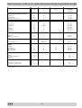
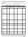
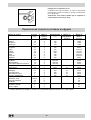
Consigli pratici per la cottura al forno
Cibo da cucinare Peso
(Kg)
Posizione cottura
ripiani dal basso
Temperatura
(°C)
Tempo di
preriscaldamento
(minuti)
Tempo di
cottura
(minuti)
Pasta
Lasagne 2,5 3 210 - 75-80
Cannelloni 2,5 3 210 - 75-80
Tagliatelle 2,5 3 210 - 75-80
Carni
Vitello 1,7 3 230 - 85-90
Pollo 1,5 3 220 - 110-115
Tacchino 3,0 3 MAX - 95-100
Anatra 1,8 3 230 - 120-125
Coniglio 2 3 230 - 105-110
Maiale 2,1 3 230 - 100-110
Agnello 1,8 3 230 - 90-95
Pesci
Sgombri 1,1 3 210-230 - 55-60
Dentice 1,5 3 210-230 - 60-65
Trota al cartoccio 1,0 3 210-230 - 40-45
Pizza
Napoletana 1,0 3 MAX 15 30-35
Torte
Biscotti 0,5 3 180 15 30-35
Crostata 1,1 3 180 15 30-35
Torta al cioccolato 1 3 200 15 45-50
Torta lievitata 1 3 200 15 50-55
Cottura al grill
Toast n.° 4 4 10
Braciole di maiale 1,5 4 30
Sgombri 1,1 4 35
Cottura al girarrosto
Vitello allo spiedo 1 2 80
Pollo allo spiedo 2 2 90
NB: i tempi di cottura sono indicativi e possono essere modificati in base ai propri gusti personali. Nelle cotture al
grill la leccarda va posta sempre al 1° ripiano a partire dal basso.

13
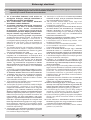
Important safety warnings
1 These instructions are only for those countries whose
symbols appear in the booklet and on the matriculation
plate of the appliance.
2 This appliance is intended for non-professional use
within the home.
3 Before using the appliance, read the instructions in this
owner’s manual carefully since you should find all the
instruction you require to ensure safe installation, use
and maintenance. Always keep this owner’s manual close
to hand since you may need to refer to it in the future.
4 When you have removed the packing, check that the appliance
is not damaged. If you have any doubts, do not use the
appliance, contact your nearest Ariston Service Centre. Never
leave the packing components (plastic bags, foamed
polystyrene, nails, etc.) within the reach of children since
they are a source of potential danger.
5 The appliance must be installed only by a qualified person in
compliance with the instructions provided. The manufacturer
declines all responsibility for improper installation which may
harm persons and animals and damage property.
6 The electrical safety of this appliance can only be guaranteed
if the cooker is correctly and efficiently earthed, in compliance
with current regulations on electrical safety. Always ensure
that the earthing is efficient; if you have any doubts call in a
qualified electrician to check the system. The manufacturer
declines all responsibility for damage resulting from a system
which has not been earthed.
7 Before plugging the appliance into the mains, check that the
specifications indicated on the date plate correspond to those
of the electrical and gas mains system of your home.
8 Check that the electrical capacity of the system and sockets
will support the maximum power of the hob, as indicated on
the data plate. If you have any doubts, call in a qualified
technician.
9 An omnipolar switch with a contact opening of at least 3 mm
or more, is required for the installation.
10 If the socket and hob plug are not compatible, have the socket
replaced with a suitable model by a qualified technician who
should also check that the cross-section of the socket cable
is suited to the power absorbed by the appliance. The use of
adaptors, multiple sockets and/or extensions, is not
recommended. If their use can not be avoided, remember to
use only single or multiple adapters and extensions which
comply with current safety regulations. In these cases, never
exceed the maximum current capacity indicated on the single
adaptor or extension and the maximum power indicated on
the multiple adapter.
11 Do not leave the appliance plugged in if it is not in use. Switch
off the main switch and gas supply when you are not using
the cooker.
12 The openings and slots used for ventilation and dispersion of
heat on the rear and below the control panel must never be
covered.
13 The user must not replace the supply cable of this appliance.
Always call an after-sales servicing centre authorised by the
manufacturer in the case of cable damage or replacement.
14 This appliance must be used for the purpose for which it was
expressly designed. Any other use (e.g. heating rooms) is
considered to be improper and consequently dangerous. The
manufacturer declines all responsibility for damage resulting
from improper and irresponsible use.
15 A number of fundamental rules must be followed when using
electrical appliances. The following are of particular
importance:
· do not touch the appliance when your hands or feet are
wet
· do not use the appliance barefooted
· never allow the Mains Cable to be stretched, pulled or
damaged if the Cooker is moved for cleaning etc. Do not
use the cooker if the Mains Cable is damaged, consult a
qualified electrician.
· do not allow the cooker to be used unsupervised by
children or persons unfamiliar with it.
16 Always switch off the electrical supply to the cooker and
allow it to cool down before carrying out any cleaning operations
etc.
17 If you are no longer using an appliance of this type, remember
to make it unserviceable by unplugging the appliance from
the mains and cutting the supply cable. Also make all
potentially dangerous parts of the appliance, safe, above all
for children who could play with the appliance.
18 To avoid accidental spillage do not use cookware with uneven
or deformed bottoms on the burners or on the electric plates.
19 Special care should be taken when using chip pans etc. in
order to avoid splashing or spillage of hot oil. They should not
be used unattended since overheated oil may boil over and
could also ignite.
20 Parts of this appliance, cooking surfaces, retain heat for
considerable periods after switching off. Care should, therefore,
be taken when touching these areas before they have
completely cooled down.
21 Never use flammable liquids such as alcohol or gasoline,
etc. near the appliance when it is in use.
22 When using small electric appliances near the hob, keep the
supply cord away from the hot parts.
23 Make sure the knobs are in the “•”/”¡” position when the
appliance is not in use.
24 When the appliance is in use, the heating elements and
some parts of the oven door become extremely hot. Make
sure you don't touch them and keep children well away.
25 Gas units need a regular air replacement for a correct
functioning. Make sure that the requirements requested
in the “Positioning” paragraph are all observed in the
owner’s manual.
26 If the cooker is placed on a pedestal, take the necessary
precautions to prevent the same from sliding off the pedestal
itself.
27 Warning: never place hot containers or items and flamma-
ble materials inside the dishwarmer drawer.
28 This owner’s manual is for a class 1 appliance (installed
independently) or class 2, subclass 1 appliances (installed
between two cabinets).
To maintain the EFFICIENCY and SAFETY of this appliance, we recommend:
• call only the Service Centers authorized by the manufacturer
• always use original Spare Parts

14
Installation
The following instructions should be read by a qualified technician
to ensure that the appliance is installed, regulated and technically
serviced correctly in compliance with current regulations.
Important: remember to unplug the appliance from the mains
before regulating the appliance or carrying out any
maintenance work.
Positioning
Important: This unit may be installed and used only in perma-
nently ventilated rooms in accordance with current National Regu-
lations. The following requirements must be observed:
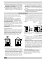
a) The room must be equipped with an exhaust system that
vents the combustion fumes to the outside. It may consist of
a hood or an electric fan that automatically starts each time
the appliance is turned on.
A Flue or Branched Flue System Directly to the outside
(only for cooking appliances)
b)
The room must also have a system to permit proper air circulation, needed
for combustion to occur normally. The flow of air needed for combustion
must not be less than 2 m
3
/h per kW of installed power. The air circulation
system may take air directly from the outside by means of a pipe with an
inner cross section of at least 100 cm
2
; the opening must not be able to be
accidentally blocked. For those appliances not equipped with a safety
device for accidental flame loss, the ventilation apertures must be in-
creased by 100%, with the minimum being 200cm
2
(Fig. A). The system
can also provide the air needed for combustion by indirect means, i.e. from
adjacent rooms fitted with air circulation tubes as described above. How-
ever, these rooms must not be common rooms or bedrooms. (Fig. B).
Detail A Adjacent Room to be
Room Ventilated
A
Examples of Ventilation Increased Opening Between
Openings Comburent Air Door and Floor
Fig. A Fig. B
c) Intensive and prolonged use of the appliance may result in
the need for supplemental air circulation, e.g. opening win-
dows or increasing mechanical venting (if present).
d) Liquified petroleum gas is heavier than the air and, therefore,
settles downwards. Thus, rooms containing LPG cylinders
must also be equipped with apertures to the outside for ven-
tilation of gas in the case of leaks. LPG cylinders must not,
therefore, be installed or stored in rooms or storage areas
that are below ground level (cellars, etc.) whether they are
partially or completely full. It is a good idea to keep only the
cylinder being used in the room, positioned so that it is not
subject to heat produced by external sources (ovens, fire-
places, stoves, etc. ) which are able to increase the tempera-
ture of the cylinder above 50°C.
Levelling Your Appliance (only on certain models)
4 support feet which are adjusted using screws are located
in the lower part of the cooker. These level off the oven
when necessary. It is essential that the cooker be standing
level.
Mounting the legs (only on certain models)
Press-fit legs are supplied which fit under the base of your
cooker.
Installation of the cooker
The appliance can be installed next to cabinets, provided the
height does not exceed that of the hob. If the cooker is placed
touching walls or sides of neighbouring cabinets, these must be
capable of withstanding a temperature rise of 50°C above room
temperature. For a correct installation of the cooker the following
precautions must be followed:
a) The cooker may be located in a kitchen, a kitonen/diner or
bed sitting room, but not in a bathroom or shower room.
b) The furniture units next to the cooker, that is higher than the
working boards, must be placed at least 600 mm from the
edge of the board. Curtains must not be fitted immediately
behind the cooker or within 110 mm. of the sides of the cooker.
c) The hoods must be installed according to the requirements
in the hood handbook.
d) Wall cabinets may be fitted in line with the sides of the base
units, providing that the lower edge of the wall cabinet is a
minimum of 420 mm. above the worktop. The minimum
distance combustible material kitchen units can be fitted
directly above the worktop is 700 mm
(Fig. C and D)
.

15
HOOD
420
Min.
min. 650 mm. with hood
min.
700 mm. without hood
mm.
600
Min. mm.
420
Min. mm.
HOOD
900
Min. mm.
420
Min.
min.
650
mm. with hood
min.
700
mm. without hood
mm.
420
Min. mm.
Fig. C Fig. D
e) The wall in contact with the back of the cooker must be of
flameproof material.
Connecting the gas
The appliance should be connected to the mains or to a gas
cylinder in compliance with current directives. Before making the
connection, check that the cooker is regulated for the gas supply
you are using. If not, follow the instructions indicated in the
paragraph “Adapting to different types of gas”. On some models
the gas supply can be connected on the left or on the right, as
necessary; to change the connection, reverse the position of the
hose holder with that of the cap and replace replace the gasket
(supplied with the appliance). When using liquid gas from a cylinder,
install a pressure regulator which complies with current directive.
Important: check that the supply pressure complies with the
values indicated in table 1 “Characteristics of the burners and
nozzles” since this will ensure safe operation, correct consumption
and ensure a longer life to your appliance.
Connection with hose
Make the connection using a gas hose complying with the the
characteristics provided in current directive. The internal diameter
of the pipe used is as follows:
- 8mm for liquid gas;
- 13mm for methane gas.
When installing the hose, remember to take the following
precautions:
• No part of the hose should touch parts whose temperature
exceeds 50°C;
• The length of the hose should be less than 1500 mm;
• The hose should not be subject to twisting or pulling, and
should not have bends or kinks.
• The hose should not touch objects with sharp edges, any
moving parts, and it should not be crushed;
• The full length of the hose should be easy to inspect in order
to check its condition;
Check that the hose fits firmly into place at the two ends and fix
it with clamps complying to current directive.If any of the above
recommendations can not be adopted, flexible metal pipes should
be used.
Should the cooker be installed according to the conditions of
Class 2, subdivision 1, only a flexible metal pipe which is in
compliance with current safety standards should be used to make
the connection to the gas mains.
Connecting a flexible jointless stainless steel pipe to a
threaded attachment
Remove the hose holder fitted on the appliance. The gas supply
pipe fitting is a threaded 1/2 gas cylindrical male attachment.
Only pipes and gaskets complying with current directives. The
full length of the pipe must not exceed 2000 mm.
Tight control
Important: when installation has been completed, check the
pipe fitting for leaks with a soapy solution. Never use a flame.
Once the connection has been made, ensure that the flexible
metal tube does not touch any moving parts and is not crushed.
Connecting the supply cable to the mains
Install a normalised plug corresponding to the load indicated on
the data plate. When connecting the cable directly to the mains,
install an omnipolar circuit-breaker with a minimum contact
opening of 3 mm between the appliance and the mains. The
omnipolar circuit breaker should be sized according to the load
and should comply with current regulations (the earth wire should
not be interrupted by the circuit breaker).
The supply cable should be positioned so that it does not reach
a temperature of more than 50°C with respect to the room tem-
perature, along its length. Before making the connection, check
that:
• the limiter valve and the home system can support the
appliance load (see data plate);
• the mains is properly earthed in compliance with current
directives and regulations;
• there is easy access to the socket and omnipolar circuit
breaker, once the hob has been installed.
N.B: never use reducers, adaptors or shunts since they can
cause heating or burning.
Adapting the cooker to different types of gas
In order to adapt the cooker to a different type of gas with respect
to the gas for which it was produced (indicated on the label
attached to the lid), follow these steps:
a) replace the hose holder mounted on the appliance with that
supplied in the bag of “cooker accessories”.
Important: the hose holder for liquid gas is marked 8, the hose
holder for methane gas is marked 13. Always fit the sealing
gasket.
b) Replacing the burner nozzles on the hob:
• remove the grids and slide the burners from their housings;
• unscrew the nozzles using a 7 mm socket spanner, and
replace them with nozzles for the new type of gas (see table
1 “Burner and nozzle characteristics”).
• replace all the components by repeating the steps in reverse
order.
c) Minimum regulation of the hob burners:
•
turn the tap to minimum;
• remove the knob and adjust the regulation screw, which is
positioned in or next to the tap pin, until the flame is small but
steady.
N.B.: in the case of liquid gas, the regulation screw must be
screwed in to the bottom.
• check that the flame does not turn off when you turn the tap

16
quickly from high to low.
d) Regulating the primary air of the burners:
The primary air of the burners requires no regulation.
Adapting to different types of gas
In order to adapt the oven to a different type of gas with
respect to the gas for which it was manufactured (indi-
cated on the label), follow these simple steps:
a) Replacing the oven burner nozzle
· open the oven door fully
· pull out the sliding oven bottom
· unscrew the burner fastening screws
V
· remove screw “V” and then the oven burner;
· Unscrew the oven burner nozzle using the special
socket spanner for the nozzles, or a 7 mm socket span-
ner, and replace it with a nozzle suited to the new type
of gas (see Table 1).
Take particular care handling the spark plug wires
and the thermocouple pipes.
· Replace all the parts, following the steps described
above in the reverse order.
b) Minimum regulation of the gas oven burner with thermostat:
• light the burner as described in the paragraph “the oven knob”
of the instruction booklet.
• turn the knob to Max for about 10 minutes and then turn the
knob to the Min setting;
• remove the knob;
• regulate the screw positioned outside the thermostat pin
until the flame is small but steady.
N.B.: in the case of liquid gas, the regulation screw must
be screwed in to the bottom.
• check that the burner does not turn off when you turn the
knob from Max to Min and and when you open and close
the oven door quickly.
Adapting the gas grill to different types of gas
Replacing the nozzle of the grill burner:
• remove the screw and then slide out the grill burner “V”
(see Fig. E);
• unscrew the grill burner nozzle using the special socket
spanner for the nozzles (see Fig. F) or better still a 7 mm
socket spanner; replace the nozzle with a nozzle for the new
type of gas (see table 1).
V
I
Fig. E Fig. F
Regulating the Primary Air for the Oven Burner
The oven burner do not need to be regulated in terms of
primary air.
Important
On completion of the operation, replace the old rating sticker
with one indicating the new type of gas used. This sticker is
available from our Service Centres.
Note
Should the pressure of the gas used be different (or vary) from
the recommended pressure, it is necessary to fit a suitable
pressure regulator onto the inlet pipe in compliance with current
National Regulations relative to “regulators for channelled gas”.

17
Burner and nozzle characteristics
Table 1 Liquid Gas Natural Gas
Burner Diameter
(mm)
Thermal Power
kW (p.c.s.*)
By-Pass
1/100
Nozzle
1/100
Flow*
g/h
Nozzle
1/100
Flow*
l/h
Nozzle
1/100
Flow*
l/h
Nominal Reduced (mm) (mm) *** ** (mm) (mm)
Fast
(Large)(R)
100 3,00 0,7 41 86 218 214 116 286 143 286
Semi Fast
(Medium)(S)
75 1,90 0,4 30 70 138 136 106 181 118 181
Auxiliary
(Small)(A)
55 1,00 0,4 30 50 73 71 79 95 80 95
Oven - 2,60 1,0 52 78 189 186 119 248 132 248
Grill - 2,50 - - 80 182 179 122 238 139 227
Supply
Pressures
Nominal (mbar)
Minimum (mbar)
Maximum (mbar)
28-30
20
35
37
25
45
20
17
25
13
6,5
18
* At 15°C and 1013 mbar- dry gas
** Propane P.C.S. = 50,37 MJ/Kg
*** Butane P.C.S. = 49,47 MJ/Kg
Natural P.C.S. = 37,78 MJ/m
3
Technical Characteristics
Inner dimensions of the oven:
Width: 43.5 cm
Depth: 43.5 cm
Height: 31 cm
Inner Volume of the Oven:
58 lt
Innder dimensions of the plate plate warmer:
Width: 46 cm
Depth: 42 cm
Height: 8.5 cm
Voltage and Frequency of Power Supply:
see data plate
Burners:
adaptable for use with all the types of gas indicated on
the data plate
This appliance conforms with the following European
Economic Community directives:
- 73/23/EEC of 19/02/73 (Low Voltage) and subsequent
modifications;
- 89/336/EEC of 03/05/89 (Electromagnetic Compatibility)
and subsequent modifications;
- 90/396/EEC of 29/06/90 (Gas) and subsequent
modifications (only for models which use gas);
- 93/68/EEC of 22/07/93 and subsequent modifications.
- 2002/96/EC
The European Directive 2002/96/EC on Waste Electrical
and Electronic Equipment (WEEE), requires that old
household electrical appliances must not be disposed of
in the normal unsorted municipal waste stream. Old
appliances must be collected separately in order to optimise
the recovery and recycling of the materials they contain
and reduce the impact on human health and the
environment. The crossed out “wheeled bin” symbol on the
product reminds you of your obligation, that when you di-
spose of the appliance it must be separately collected.
Consumers should contact their local authority or retailer
for information concerning the correct disposal of their old
appliance.
S
S
R
A
K6 G21S/R
K6 G21/R

18
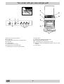
The cooker with gas oven and gas grill
C
J
A Tray for Catching Overflows
B Gas Burner
C Instantaneous Electronic Lighting Device
D Top Grate
E Control Panel
F Adjustable Feet or Legs
G Dripping Pan or Baking Sheet
J Safety Device (only on a few models)
K Oven Rack
L Electronic Lighting for Hob Burners
M Oven and Grill Control Knob
N Control Knobs for Gas Burners on Hob
O Button for Oven and Rotisserie Light (only on a few
models)
P Timer Knob
M
P L
O
N
F
A
E
K
G
D
B

19
The different functions and uses of the oven
The various functions included in the cooker are selected by
operating the control devices located on the cooker control panel.
Control Knobs for the Gas Burners on the Hob
The position of the gas burner controlled by each one of the
knobs is shown by a symbol of a solid ring:
•. To light one of the
burners, hold a lighted match or lighter near the burner. Press
down and turn the corresponding knob in the counter-clockwise
direction to the maximum
setting. Each burner can be oper-
ated at its maximum, minimum or intermediate power. Shown on
the knob are the different symbols for off
• (the knob is on this
setting when the symbol lines up with the reference mark on the
control panel), for maximum
and minimum .
To obtain these settings, turn the knob counter-clockwise with
respect to the off position. To turn off the burner, turn the knob
clockwise until it stops (corresponding again with the
• symbol).
Electronic Lighting of the Hob Burners
Some models are equipped with instant electronic lighting of the
gas burners located on the hob, which can be identified by the
presence of an igniter device (see detail C). This device is acti-
vated by lighting pressing on the “L” button, identified by the
1
symbol. To turn on a burner, simply press the “L” button and
then press while, at the same time, pressing in and turning the
control knob for the burner in the anticlockwise direction until the
burner lights. To light the burner immediately, it is recom-
mended that the button be pressed first and then the knob
turned.
Caution: If the burner accidentally goes out, turn off the burner
using the knob and wait at least one minute before relight-
ing.
Models with Hob Gas Burner Safety Devices to Prevent
Leaks (only on a few models)
These models can be identified by the presence of the device
itself (see detail J).
Important: Since the hob burners are equipped with a safety
device, you must hold the control knob in for about 3 seconds
after the burner has been lighted to allow the gas to pass until the
safety thermocouple has heated.
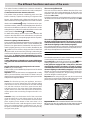
Notice: The first time you use your appliance, we recom-
mend that you set the thermostat to the highest setting
and leave the oven on for about half an hour with nothing
in it, with the oven door shut. Then, open the oven door
and let the room air. The odour that is often detected dur-
ing this initial use is due to the evaporation of substances
used to protect the oven during storage and until it is in-
stalled.
Attention: Only use the bottom shelf of the oven when
using the rotisserie to cook (where present). For all other
types of cooking, never use the bottom shelf and never
place anything on the bottom of the oven when it is in
operation because this could damage the enamel. Always
place your cookware (dishes, aluminium foil, etc. etc.) on
the grate provided with the appliance inserted especially
along the oven guides.
The oven and grill knob (M)
This knob is used to select the different functions of the oven
and choose the right cooking temperature for the food to be
prepared in the oven among the temperatures shown on the
knob (from Min to Max).
To light the oven burner, hold a lighted match or lighter near hole
“F” and turn the oven knob counter anti clockwise up to the Max
position.
F
The models equipped with a safety device on oven burner,
the knob must be kept pressed in for about 6 seconds to
activate the flame failure device. (For the models provided
with electronic lighting see the relative paragraph).
The cooking temperature is selected by matching the desired
temperature with the permanent reference on the panel; the com-
plete range of temperatures is shown below:
Min • 160 • 180 • 220 Max
150 155 170 200 250
The selected temperature is reached automatically and it is kept
constant by the knob-controlled thermostat.
To use the grill, turn the knob clockwise till to setting
, after
holding a lighted match or a lighter close to the grill burner.
In the grill burner equipped with a safety device, the knob
must be held pressed in for about 6 seconds in order to
activate the flame failure device (for the model provided with
electronic lighting see the relative paragraph). In this way the
infrared ray comes on for browning the food or cooking roast,
chops, sausages, roast-beef, etc.; for grill cooking, place a drip-
pan under the grill to catch the grease.
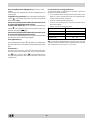
Important: when using the grill, the oven door must be left
partly open by positioning the deflector “D” between door and
panel to prevent the cooker knobs from overheating.
D
Important Notice: In the event the flame for the oven acciden-
tally goes out, turn the control knob for the burner to the off
position and do not relight the burner for at least one minute.

20
Oven and grill electronic lighting device (L) (only on a few
models)
Some models are equipped with electronic lighting device on
oven and grill.
To light the oven gas burner press in the botton marked by the
symbol
1
, press deeply and turn the oven knob clockwise, till
to the position “Max”.
It is necessary to hold pressed in the knob for about 4 seconds
in order to activate the flame failure device.
To light on the grill burner press in the bottom marked by the
symbol
1
, press deeply and turn the oven knob counter clock
wise till to the position
(grill).
It is necessary to hold pressed in the knob for about 4 seconds
in order to activate the flame failure device.
In case of lack of electricity light the oven or grill manuall, following
the instruction of “the oven knob paragraph”.
Oven light button (O)
This is marked by the symbol
I
and switchs on the light inside
the oven so that you can control the cooking without opening the
door.
Timer Knob (P)
In order to use the timer, it must be wound by turning the
"P" knob almost one complete turn in the clockwise direc-
tion
. Then, turning it back , set the desired time by
lining up the number for the minutes with the mark on the
control panel.
Practical Advice on Using the Burners
To use the burners as efficiently as possible, some basic
guidelines should be followed:
• Use cookware that is the right size for each burner (see
table) in order to prevent the flame from spreading be-
yond the bottom of the cookware.
• Only use cookware with flat bottoms.
• As soon as the boiling point is reached, turn the knob to
the lowest setting.
• Always use lids with pots and pans.
Bruciatore ø Diametro recipienti (cm)
Rapido (R) 24 – 26
Semi Rapido (S) 16 – 20
Ausiliario (A) 10 – 14
N.B.: On models equipped with a reduction grid, the grid
should only be used with the auxiliary burner when cookware
with a diameter of less than 12 cm is used.
La pagina si sta caricando...
La pagina si sta caricando...
La pagina si sta caricando...
La pagina si sta caricando...
La pagina si sta caricando...
La pagina si sta caricando...
La pagina si sta caricando...
La pagina si sta caricando...
La pagina si sta caricando...
La pagina si sta caricando...
La pagina si sta caricando...
La pagina si sta caricando...
La pagina si sta caricando...
La pagina si sta caricando...
La pagina si sta caricando...
La pagina si sta caricando...
La pagina si sta caricando...
La pagina si sta caricando...
La pagina si sta caricando...
La pagina si sta caricando...
La pagina si sta caricando...
La pagina si sta caricando...
La pagina si sta caricando...
La pagina si sta caricando...
La pagina si sta caricando...
La pagina si sta caricando...
La pagina si sta caricando...
La pagina si sta caricando...
La pagina si sta caricando...
La pagina si sta caricando...
La pagina si sta caricando...
La pagina si sta caricando...
La pagina si sta caricando...
La pagina si sta caricando...
La pagina si sta caricando...
La pagina si sta caricando...
La pagina si sta caricando...
La pagina si sta caricando...
La pagina si sta caricando...
La pagina si sta caricando...
La pagina si sta caricando...
La pagina si sta caricando...
La pagina si sta caricando...
La pagina si sta caricando...
La pagina si sta caricando...
La pagina si sta caricando...
La pagina si sta caricando...
La pagina si sta caricando...
-
 1
1
-
 2
2
-
 3
3
-
 4
4
-
 5
5
-
 6
6
-
 7
7
-
 8
8
-
 9
9
-
 10
10
-
 11
11
-
 12
12
-
 13
13
-
 14
14
-
 15
15
-
 16
16
-
 17
17
-
 18
18
-
 19
19
-
 20
20
-
 21
21
-
 22
22
-
 23
23
-
 24
24
-
 25
25
-
 26
26
-
 27
27
-
 28
28
-
 29
29
-
 30
30
-
 31
31
-
 32
32
-
 33
33
-
 34
34
-
 35
35
-
 36
36
-
 37
37
-
 38
38
-
 39
39
-
 40
40
-
 41
41
-
 42
42
-
 43
43
-
 44
44
-
 45
45
-
 46
46
-
 47
47
-
 48
48
-
 49
49
-
 50
50
-
 51
51
-
 52
52
-
 53
53
-
 54
54
-
 55
55
-
 56
56
-
 57
57
-
 58
58
-
 59
59
-
 60
60
-
 61
61
-
 62
62
-
 63
63
-
 64
64
-
 65
65
-
 66
66
-
 67
67
-
 68
68


Indesit K6G21(B)/R Guida utente
- Categoria
- Barbecue
- Tipo
- Guida utente
- Questo manuale è adatto anche per
in altre lingue
- slovenčina: Indesit K6G21(B)/R Užívateľská príručka
- română: Indesit K6G21(B)/R Manualul utilizatorului
Documenti correlati
Altri documenti
-
Whirlpool C 24 G (W)I Guida utente
-
-
-
Electrolux EHS7405K Manuale utente
-
United HHP-7267 User Instructions
-
RAVAK Classic II 1300 double washbasin Guida d'installazione
-
-
 UniPOS FD6110L Manuale utente
-
 UniPOS FD6130L Manuale del proprietario
-
 UniPOS FD6120&6130L Manuale utente


