Lindy 38264 Manuale utente
- Categoria
- Switch KVM
- Tipo
- Manuale utente
Questo manuale è adatto anche per

© LINDY Group - FIRST EDITION (May 2019)
KVM Over IP Extender
User Manual English
Benutzerhandbuch Deutsch
Manuel Utilisateur Français
Manuale Italiano
No. 38264 – Transmitter No. 38265 – Receiver
lindy.com
Tested to Comply with
FCC Standards
For Home and Office Use!


User Manual English
Introduction
Thank you for purchasing the Lindy KVM Over IP Extender system. This product has been designed to
provide trouble free, reliable operation. It benefits from both a LINDY 2-year warranty and free lifetime
technical support. To ensure correct use, please read this manual carefully and retain it for future
reference.
The Lindy KVM Over IP Extender lets you control an HDMI and USB source through a standard Ethernet
network, reaching a maximum resolution of 4K30Hz and adding a convenient IR extension feature to let
you control the remote appliance through a native IR remote control. This system can work both in point
to point (using one transmitter No.38264 and receiver No.38265 directly connected with an Ethernet cable)
and point to multi-point (using one transmitter and many receivers connected through a dedicated Ethernet
Switch or via a dedicated VLAN) configurations, enabling the control of a single system from different
remote locations.
Package Contents
Transmitter Unit (No.38264)
Transmitter Unit
Multi-country Power Supply
USB Type A Male to Type A Male cable
IR Transmitter Cable
This manual
Receiver Unit (No.38265)
Receiver Unit
Multi-country Power Supply
IR Receiver Cable
This manual
Specification
Supports HDMI 1.4b, HDCP 1.4 (Max resolution 4K@30Hz 4:4:4 – 8 bit colour depth)
Supports 8/10/12 bit colour depths at 1080p
Supports USB HID devices (Keyboard & Mouse only)
Supports IR signals extension (25 to 56kHz)
Max Distance in point to point configuration: 150m (492.12ft) using Cat.5e/6 UTP cable
Supports point to multi-point configurations through a dedicated network or dedicated VLAN

User Manual English
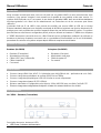
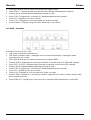
Overview
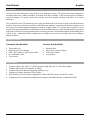
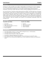
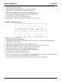
No. 38264 – Transmitter
Port, button and LED description:
Power LED: Power indicator
Status LED: Status indicator - slow flash: normal operation / quick flash: abnormal operation
HDMI LED: Indicates the presence of an HDMI signal when lit
USB-PC port: Connect this port to a host device’s USB port
Reset button: Press this button to re-initialize the unit
DC/5V port: Connect to the DC connector of the included power supply
UTP Network port: Connect a Cat.5e/6 cable
IR-TX port: Connect the included IR Transmitter cable
HDMI IN port: Connect the video source using an HDMI cable
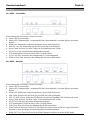
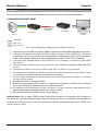
No. 38265 – Receiver
Port, button and LED description:
Power LED: Power indicator
Status LED: Status indicator - slow flash: normal operation / quick flash: abnormal operation
HDMI LED: Indicates the presence of an HDMI signal when lit
USB button: Press to get control of the source USB device
USB 1 & USB 2 ports: Connect these ports to a standard USB keyboard and mouse
Reset button: Press this button to re-initialize the unit
DC/5V port: Connect to the DC connector of the included power supply
UTP Network port: Connect a Cat.5e/6 cable
IR-RX port: Connect the included IR Receiver cable
EDID button: Press for 3 seconds to copy the connected display EDID to all receivers within the
same network segment
HDMI OUT port: Connect to an HDMI display / projector using an HDMI cable

User Manual English
Installation
Please refer to the following installation examples to set up your system.
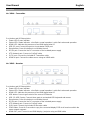
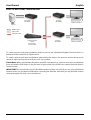
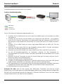
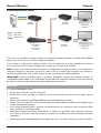
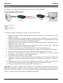
POINT TO POINT CONFIGURATION
In this configuration please follow these steps:
1. Connect your HDMI source to the HDMI Transmitter using a High Speed HDMI cable (not included).
2. Connect one end of the Cat.5e/6 cable (maximum length 150m or 492.12ft – not included) to the
RJ45 (UTP) port on the Transmitter, and the other end of the cable to the RJ45 (UTP) port of the
Receiver. Lindy recommends using solid core installation Cat.5e UTP cable or higher.
3. Connect your HDMI display device to the HDMI OUT port on the Receiver using a High Speed
HDMI cable.
4. Connect a free USB port on the source device to the USB-PC port on the Transmitter using the
included USB Type A cable.
5. Connect a USB keyboard and mouse to the USB 1 and USB 2 ports on the Receiver.
6. To use the IR remote control functionality, connect the included IR Transmitter cable to the 3.5mm
IR port on the Transmitter and the IR Receiver cable to the IR port on the Receiver.
7. Place the IR Transmitter in front of the IR port of the equipment you want to control, ensuring the
Eye is in a clear line of sight.
8. Power on both the HDMI source and display.
9. Plug the included DC power supply into the Transmitter and Receiver. The power LED will
illuminate on both units to show they are receiving power.
10. The devices will start to communicate and set up the link. When the link is set up the Status LED
will illuminate and flash slowly on both units.
11. You can now start using the remote console.
Please Note: In order to copy the EDID check that the Transmitter and Receiver are connected and
powered on correctly. When the display shows ‘Wait Link Up’ press and hold the EDID button on the
Receiver for at least 3 seconds and release when the display becomes blank. The EDID has now been
successfully updated.
Up to 150m (492.12ft)
HDMI Cable
USB Cable
Cat.5e/6 Cable
Control Console
Source
Transmitter
(No.38264)
Receiver
(No.38265)

User Manual English
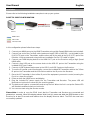
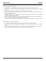
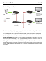
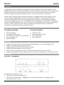
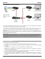
POINT TO MULTI POINT CONFIGURATION
To create a point to multi point installation please be sure to use a dedicated Gigabit Ethernet Switch or a
dedicated VLAN created on a Gigabit switch.
To install a point to multi-point configuration please follow the steps in the previous section taking care to
repeat all steps involving the receiver for each unit installed.
Please Note: When using multiple Receivers and USB input devices in a point to multi-point configuration
press and hold the USB button on any Receiver to gain control of the HDMI source device from that specific
control console.
IMPORTANT! As the extender uses the Broadcast protocol please ensure that you are using a dedicated
network switch or a port based VLAN before connecting the extender, otherwise you may flood the network
causing disruption for other connected devices.
HDMI Cable
USB Cable
Cat.5e/6 Cable
Control Console 1
Source
Control Console 2
Transmitter
(No.38264)
Transmitter
(No.38264)
Transmitter
(No.38264)
Transmitter
(No.38264)
Transmitter
(No.38264)
Receiver
(No.38265)
Receiver
(No.38265)
Ethernet Gigabit
Switch
(i.e. No.25047 -
Not Included)

User Manual English
Troubleshooting
There is no display on the screen.
Check that the DC plug and jack used by the external power supply are firmly connected.
Check that the Cat.5e/6 or higher cable is plugged in correctly and that the Status LED is flashing
slowly.
Check that the HDMI source and display are both powered on and active.
Power off all the devices, then power on in this order: first, the Transmitter and Receivers, then the
display and finally the source.
For some HDMI devices it may be helpful to unplug and re-plug their HDMI connection to re-initiate
the HDMI handshake and recognition.
Reduce the length of HDMI cable used, or use a higher quality cable. Please refer to the Specification
section for the maximum distance/resolution/cable combinations.
Check no other IP device is generating traffic on the same network dedicated to the extender system.
USB Keyboard or mouse are not working
Check that the DC plug and jack used by external power supply are firmly connected.
Check that the CAT5e/6 or higher cable is plugged in correctly and that the Status LED is flashing
slowly.
Check that the USB keyboard and mouse work correctly when connected directly to the source device.
If you are using wireless USB devices, please replace them with wired devices.

User Manual English
Einführung
Wir freuen uns, dass Ihre Wahl auf ein LINDY-Produkt gefallen ist und danken Ihnen für Ihr Vertrauen.
Sie können sich jederzeit auf unsere Produkte und einen guten Service verlassen. Dieses Lindy KVM
Over IP Extendersystem unterliegt einer 2-Jahres LINDY Herstellergarantie und lebenslangem
kostenlosen, technischen Support. Bitte lesen Sie diese Anleitung sorgfältig und bewahren Sie sie auf.
Der Lindy KVM Over IP Extender ermöglicht die Kontrolle einer HDMI- und USB-Quelle über ein Standard-
Ethernetnetzwerk. Dabei kann eine maximale Auflösung von 4K30Hz erreicht werden. Eine komfortable
IR-Erweiterung erlaubt die Steuerung des entfernten Geräts mit der vorhandenen IR-Fernbedienung.
Dieses System unterstützt sowohl Punkt-zu-Punkt- (ein Transmitter No. 38264 und ein Receiver No.
38265 werden direkt mit einem Ethernetkabel verbunden) als auch Punkt-zu-Mehrpunkt-Konfigurationen
(ein Transmitter und viele Receiver werden mit einem dedizierten Ethernet Switch oder einem dedizierten
VLAN verbunden), wobei die Kontrolle eines Systems von verschiedenen dezentralen Stellen aus
ermöglicht wird.
Lieferumfang
Transmitter (No. 38264)
Transmitter
Multi-Country Netzteil
USB-Kabel Typ A Stecker / Stecker
IR-Transmitterkabel
Dieses Handbuch
Receiver (No. 38265)
Receiver
Multi-Country Netzteil
IR-Receiverkabel
Dieses Handbuch
Spezifikationen
Unterstützt HDMI 1.4b, HDCP 1.4 (max. Auflösung 4K@30Hz 4:4:4 – 8 Bit Farbtiefe)
Unterstützt 8/10/12 Bit Farbtiefe bei 1080p
Unterstützt USB-HID-Geräte (nur Maus und Tastatur)
Unterstützt IR-Signalverlängerung (25 bis 56kHz)
Max. Distanz bei Punkt-zu-Punkt-Konfiguration: 150m (492.12ft) mit Cat.5e/6 UTP-Kabel
Unterstützt Punkt-zu-Mehrpunkt-Konfigurationen mit einem dedizierten Netzwerk oder dediziertem
VLAN

Benutzerhandbuch Deutsch
Überblick
No. 38264 – Transmitter
Beschreibung der Anschlüsse, Tasten und LEDs:
Power LED: Stromanzeige
Status LED: Statusanzeige – langsames Blinken: Normalbetrieb / schnelles Blinken: anomaler
Betrieb
HDMI LED: Aufleuchten zeigt Vorhandensein eines HDMI-Signals an
USB-PC Port: Zur Verbindung mit dem USB Port des Hostcomputers
Reset-Taste: Drücken Sie diese Taste zum Reinitialisieren des Geräts
DC/5V Port: Zum Anschluss des beiliegenden Netzteils
UTP Netzwerkport: Zum Anschluss eines Cat.5e/6-Kabels
IR-TX Port: Zum Anschluss des beiliegenden IR-Transmitterkabels
HDMI IN Port: Zum Anschluss der Videoquelle mit einem HDMI-Kabel
No. 38265 – Receiver
Beschreibung der Anschlüsse, Tasten und LEDs:
Power LED: Stromanzeige
Status LED: Statusanzeige – langsames Blinken: Normalbetrieb / schnelles Blinken: anomaler
Betrieb
HDMI LED: Aufleuchten zeigt Vorhandensein eines HDMI-Signals an
USB-Taste: Drücken Sie die Taste zur Kontrolle des USB-Quellgeräts
USB 1 & USB 2 Ports: Verbinden Sie diese Ports mit einer Standard-USB-Tastatur und -maus
Reset-Taste: Drücken Sie diese Taste zum Reinitialisieren des Geräts
DC/5V Port: Zum Anschluss des beiliegenden Netzteils
UTP Netzwerkport: Zum Anschluss eines Cat.5e/6-Kabels
IR-RX Port: Zum Anschluss des beiliegenden IR-Receiverkabels
EDID-Taste: Drücken der Taste für 3 Sekunden zum Kopieren der EDID des angeschlossenen
Displays zu allen Receivern innerhalb desselben Netzwerksegments
HDMI OUT Port: Zum Anschluss eines HDMI Displays/Projektors mit einem HDMI-Kabel

Benutzerhandbuch Deutsch
Installation
Installationsbeispiele zum Einrichten eines Systems:
Punkt-zu-Punkt-Konfiguration
Gehen Sie bei dieser Konfiguration folgendermaßen vor:
1. Schließen Sie Ihre HDMI-Quelle mit einem High-Speed-HDMI-Kabel (nicht enthalten) am HDMI
Transmitter an.
2. Schließen Sie ein Ende des Cat.5e/6-Kabels (max. Länge 150m oder 492.12ft – nicht enthalten)
am RJ45 (UTP) Port des Transmitters an und das andere Ende des Kabels am RJ45 (UTP) Port
des Receivers. Lindy empfiehlt die Verwendung von Cat.5e (oder höher) UTP-Kabeln mit starren
Adern.
3. Schließen Sie Ihr HDMI Display mit einem High-Speed-HDMI-Kabel am HDMI OUT Port des
Receivers an.
4. Verbinden Sie einen freien USB Port des Quellgeräts mit dem USB-PC Port des Transmitters.
Verwenden Sie dazu das beiliegende USB-Kabel Typ A.
5. Verbinden Sie eine USB-Tastatur und –maus mit den Ports USB 1 und USB 2 am Receiver.
6. Um die IR-Fernbedienungsfunktion zu verwenden, schließen Sie das beiliegende IR-
Transmitterkabel am 3.5mm IR Port des Transmitters an und das IR-Receiverkabel am IR Port des
Receivers.
7. Platzieren Sie den IR Transmitter vor dem IR Port des Geräts, das Sie steuern möchten. Das IR-
Auge muss direkte Sichtverbindung haben.
8. Schalten Sie HDMI-Quelle und das Display ein.
9. Schließen Sie die beiliegenden Netzteile an Transmitter und Receiver an. Die Power LED wird auf
beiden Geräten aufleuchten um anzuzeigen, dass sie mit Strom versorgt werden.
10. Die Geräte beginnen zu kommunizieren und eine Verbindung aufzubauen. Sobald die Verbindung
hergestellt ist, wird die Status LED aufleuchten und auf beiden Geräten langsam blinken.
11. Die Bedienkonsole ist nun einsatzbereit..
Beachten Sie bitte, dass für das Kopieren der EDID-Daten Transmitter und Receiver korrekt
angeschlossen und eingeschaltet sind. Wenn das Display ‘Wait Link Up’ anzeigt, drücken und halten Sie
bitte die EDID-Taste auf dem Receiver für mindestens 3 Sekunden und lassen Sie los, wenn die Anzeige
auf dem Display erlischt. Die EDID ist dann upgedated.
bis 150m (492.12ft)
HDMI-Kabel
USB-Kabel
Cat.5e/6-Kabel
Bedienkonsole
Quelle
Transmitter
(No.38264)
Receiver
(No.38265)

Benutzerhandbuch Deutsch
Punkt-zu-Mehrpunkt-Konfiguration
segr
Für eine Punkt-zu-Mehrpunkt-Konfiguration verwenden Sie bitte einen dedizierten Gigabit Ethernet Switch
oder ein dediziertes VLAN auf einem Gigabit Switch.
Zur Installation einer Punkt-zu-Mehrpunkt-Konfiguration folgen Sie bitte den Schritten in der Anleitung
oben (unter ‚Punkt-zu-Punkt-Konfiguration‘). Achten Sie darauf, dass Sie den Schritt zum Anschluss des
Receivers für jeden einzelnen Receiver wiederholen.
Achten Sie bitte darauf, dass Sie die USB-Taste auf jedem Receiver gedrückt halten, wenn Sie mehrere
Receiver und USB-Eingabegeräte in einer Punkt-zu-Mehrpunkt-Konfiguration verwenden, um von der
entsprechenden Konsole Kontrolle über die HDMI-Quelle zu erhalten.
Achtung! Da der Extender ein Broadcastprotokoll nutzt, vergewissern Sie sich, dass Sie einen dedizierten
Netzwerkswitch oder ein portbasiertes VLAN verwenden, ehe Sie den Extender anschließen. Anderenfalls
könnten Sie das Netzwerk mit Daten überfluten, was zu Störungen bei anderen angeschlossenen Geräten
führen kann.
HDMI-Kabel
USB-Kabel
Cat.5e/6-Kabel
Bedienkonsole 1
Quelle
Bedienkonsole 2
Transmitter
(No.38264)
Transmitter
(No.38264)
Transmitter
(No.38264)
Transmitter
(No.38264)
Transmitter
(No.38264)
Receiver
(No.38265)
Receiver
(No.38265)
Ethernet Gigabit
Switch
(z.B. No.25047 –
nicht enthalten)

Benutzerhandbuch Deutsch
Fehlersuche
Der Bildschirm zeigt kein Bild.
Überprüfen Sie, ob der DC-Stecker des Netzteils fest in der Buchse sitzt.
Überprüfen Sie, ob das Cat.5e/6-Kabel korrekt angeschlossen ist und die Status LED langsam blinkt.
Überprüfen Sie, ob HDMI-Quelle und das Display eingeschaltet und aktiv sind.
Schalten Sie alle Geräte aus und dann in dieser Reihenfolge wieder ein: Transmitter, Receiver, Display
und zum Schluss das Quellgerät.
Bei einigen HDMI-Geräten ist es hilfreich, die HDMI-Verbindung zu trennen und dann erneut eine
Verbindung herzustellen, um HDMI Handshake und –Erkennung neu anzustoßen.
Reduzieren Sie die Länge des verwendeten HDMI-Kabels oder verwenden Sie ein höherwertiges
Kabel. Im Abschnitt ‚Spezifikationen’ finden Sie Angaben zu maximaler Entfernung, Auflösung und
Kabel.
Prüfen Sie, ob kein anderes IP-Gerät Datenverkehr im dedizierten Netz des Extendersystems erzeugt.
USB-Tastatur und –Maus funktionieren nicht
Überprüfen Sie, ob der DC-Stecker des Netzteils fest in der Buchse sitzt.
Überprüfen Sie, ob das Cat.5e/6-Kabel korrekt angeschlossen ist und die Status LED langsam blinkt.
Überprüfen Sie, ob USB-Tastatur und –Maus korrekt funktionieren, wenn sie direkt am Quellgerät
angeschlossen werden.
Bei Verwendung kabelloser USB-Geräte ersetzen Sie diese bitte mit Geräten mit Kabel

Manuel Utilisateur Français
Introduction
Nous sommes heureux que votre choix se soit porté sur un produit LINDY et vous remercions de votre
confiance. Vous pouvez compter à tout moment sur la qualité de nos produits et de notre service. Ce
système KVM Extender sur IP est soumis à une durée de garantie LINDY de 2 ans et d’une assistance
technique gratuite à vie. Merci de lire attentivement ces instructions et de les conserver pour future
référence.
L'extender KVM sur IP de LINDY vous permet de contrôler une source HDMI et USB via un réseau
Ethernet standard, atteignant une résolution maximale de 4K30Hz et ajoutant une fonction d'extension IR
pratique pour vous permettre de contrôler l'appareil distant via une télécommande IR native. Ce système
peut fonctionner aussi bien en configuration point à point (en utilisant un émetteur n° 38264 et un récepteur
n° 38265 directement connectés avec un câble Ethernet) qu'en configuration multipoint (en utilisant un
émetteur et plusieurs récepteurs connectés via un commutateur Ethernet dédié ou via un VLAN dédié),
permettant de contrôler un système unique depuis différents emplacements distants.
Contenu de l’emballage
Emetteur (No.38264)
Emetteur (Transmitter)
Alimentation multi-pays
Câble USB Type A mâle/mâle
Câble émetteur IR
Ce manuel
Récepteur (No.38265)
Récepteur (Receiver)
Alimentation multi-pays
Câble récepteur IR
Ce manuel
Spécifications
Prise en charge HDMI 1.4b, HDCP 1.4 (résolution max. 4K@30Hz 4:4:4 – profondeur de coul. 8 bit)
Prise en charge des profondeurs de couleur 8/10/12 bit en 1080p
Prise en charge des périphériques USB HID (clavier et souris uniquement)
Prise en charge des signaux IR (25 à 56kHz)
Distance maximale en configuration point à point: 150m (492.12ft) avec un câble Cat.5e/6 UTP
Prise en charge des configurations multipoint à l’aide d’un réseau dédié ou d’un VLAN
Vue d’ensemble
No. 38264 – Emetteur (Transmitter)
Description des ports, boutons et LED:
LED Power: indicateur d’alimentation

Manuel Utilisateur Français
LED Status: indicateur d’état – clignotement lent: fonctionnement conforme / clignotement rapide:
fonctionnement non conforme
LED HDMI: indique la présence d’un signal HDMI si allumé
Port USB-PC: à connecter à un port USB de votre hôte
Bouton Reset: appuyez sur ce bouton pour réinitialiser l’unité
Port DC/5V: connecte la prise DC ronde de l’alimentation fournie
Port réseau UTP: connecte un câble Cat.5e/6
Port IR-TX: connecte le câble émetteur IR fourni
Port HDMI IN: connecte la source vidéo en utilisant un câble HDMI
No. 38265 – Récepteur (Receiver)
Description des ports, boutons, LED:
LED Power: indicateur d’alimentation
LED Status: indicateur d’état – clignotement lent: fonctionnement conforme / clignotement rapide:
fonctionnement non conforme
LED HDMI: indique la présence d’un signal HDMI si allumé
Bouton USB: appuyez sur ce bouton pour contrôler du périphérique USB de la source
Ports USB 1 & USB 2: connectez ces ports à la souris et au clavier
Bouton Reset: appuyez sur ce bouton pour réinitialiser l’unité
Port DC/5V: connecte la prise DC ronde de l’alimentation fournie
Port réseau UTP: connecte un câble Cat.5e/6
Port IR-RX: connecte le câble capteur IR inclus
Bouton EDID: appuyez sur ce bouton pendant 3 secondes pour copier l’EDID de l’affichage connecté
sur tous les récepteurs connectés sur le même segment réseau
Port HDMI OUT: Connecte un écran HDMI / projecteur en utilisant un câble HDMI

Manuel Utilisateur Français
Installation
Merci de vous référer aux exemples d’installation suivant pour mettre en place votre installation.
CONFIGURATION POINT A POINT
Pour cette configuration veuillez suivre les étapes suivantes:
1. Connectez la source HDMI à l’émetteur HDMI en utilisant un câble HDMI High Speed (non fourni).
2. Connectez une extrémité du câble Cat.5e/6 (longueur maximale 150m ou 492.12ft – non fourni)
au port RJ45 (UTP) de l’émetteur et l’autre extrémité de ce câble au port RJ45 (UTP) du récepteur.
LINDY recommande l’utilisation de câble d’installation monobrin Cat.5e UTP ou supérieur.
3. Connectez votre affichage HDMI au port HDMI OUT sur le récepteur en utilisant un câble HDMI
High Speed.
4. Connectez un port USB de la source au port USB-PC sur l’émetteur en utilisant le câble USB Type
A inclus.
5. Connectez un clavier et une souris USB aux ports USB 1 et USB 2 sur le récepteur.
6. Pour utiliser la fonctionnalité de contrôle IR, connectez le câble émetteur IR inclus au port IR 3.5mm
sur l’émetteur et le câble capteur IR au port IR sur le récepteur.
7. Placez le câble IR émetteur en face du capteur IR de votre équipement à contrôler, en assurant
une ligne de mire directe.
8. Alimentez la source et l’affichage HDMI.
9. Branchez les alimentations DC incluses sur l’émetteur et le récepteur. La LED power va s’allumer
sur les deux unités pour indiquer qu’elles sont bien alimentées.
10. Les appareils vont communiquer et établir une liaison. Lorsque cette liaison sera effective la LED
Status va s’allumée et clignoter lentement sur les deux unités.
11. Vous pouvez démarrer l’utilisation sur la console distante.
Merci de noter: Afin de copier l’EDID veuillez vérifier que l’émetteur et le récepteur sont connectés et
bien alimentés. Lorsque l’affichage indique ‘Wait Link Up’ appuyez tout en maintenant le bouton EDID sur
le récepteur pendant au moins 3 secondes et relâchez-le lorsque l’affichage devient inactif. L’EDID a été
mise à jour avec succès.
Jusqu’à 150m
(492.12ft)
Câble HDMI
Câble USB
Câble Cat.5e/6
Console de
contrôle
Source
Emetteur
(No.38264)
Récepteur
(No.38265)

Manuel Utilisateur Français
CONFIGURATION MULTIPOINT
Pour créer une installation multipoint veuillez vous assurer d’utiliser un réseau un switch réseau Gigabit
dédié ou un VLAN créé sur un switch Gigabit manageable.
Pour installer la configuration multipoint veuillez suivre les étapes de la section précédente en prenant
soin de répéter toutes les étapes impliquant le récepteur pour chaque unité installée.
Note: Lorsque vous utilisez plusieurs récepteurs et périphériques d'entrée USB dans une configuration
multipoint, appuyez et maintenez enfoncer le bouton USB de n'importe quel récepteur pour prendre le
contrôle du périphérique source HDMI à partir de cette console de commande spécifique.
IMPORTANT! Comme l’extender utilise le protocole Broadcast, veuillez vous assurer d’utiliser un
commutateur réseau dédié ou un VLAN basé sur port avant de connecter l’extender, sinon vous risquez
de saturer le réseau et de perturber les autres périphériques connectés.
Dépannage
Il n’y a pas d’affichage à l’écran.
Vérifiez que la fiche DC est bien connectée.
Vérifiez que le câble Cat.5e/6 ou supérieur est correctement branché et que la LED Status clignote
lentement.
Vérifiez que la source et l’affichage HDMI sont tous deux alimentés et actifs.
Eteignez tous les appareils, puis allumez-les dans cet ordre: d’abord l’émetteur et le récepteur, puis
l’écran et finalement la source.
Pour certains appareils HDMI, il peut être utile de débranchez puis rebrancher leurs connexions HDMI
pour réinitialiser le handshake HDMI.
Réduisez la longueur des câbles HDMI utilisés, ou utilisez une qualité de câble supérieure. Merci de
vous référer à la section Spécifications pour connaître les combinaisons distance/résolutions/câbles
maximales.
Vérifiez qu’aucun autre périphérique IP ne génère du trafic sur le réseau dédié au système extender.
Câble HDMI
Câble USB
Câble Cat.5e/6
Console de
Contrôle 1
Source
Console de
Contrôle 2
Transmitter
(No.38264)
Transmitter
(No.38264)
Transmitter
(No.38264)
Transmitter
(No.38264)
Emetteur
(No.38264)
Récepteur
(No.38265)
Récepteur
(No.38265)
Switch Ethernet
Gigabit
(ex. No.25047 –
non fourni)

Manuel Utilisateur Français
Clavier et souris USB ne fonctionne pas
Vérifiez que la fiche DC est bien connectée
Vérifiez que le câble Cat.5e/6 ou supérieur est correctement branché et que la LED Status clignote
lentement.
Vérifiez que le clavier et la souris USB fonctionnent correctement lorsqu’ils sont directement connectés
à la source.
Veuillez utiliser des périphériques USB filaires, les claviers et souris sans fil ne sont pas pris en charge.

Manuale Italiano
Introduzione
Vi ringraziamo per aver acquistato il sistema KVM Over IP Extender Lindy. Questo prodotto è stato
progettato per garantirvi la massima affidabilità e semplicità di utilizzo ed è coperto da 2 anni di garanzia
LINDY oltre che da un servizio di supporto tecnico a vita. Per assicurarvi di farne un uso corretto vi
invitiamo a leggere attentamente questo manuale e a conservarlo per future consultazioni.
Il KVM Over IP Extender Lindy consente di controllare una sorgente HDMI e USB attraverso un rete
Ethernet standard, raggiungendo la risoluzione massima di 4K30Hz a cui aggiunge la funzione di
estensione del segnale IR per controllare le sorgenti anche attraverso il loro telecomando IR nativo.
Questo sistema può funzionare sia in modalità punto-punto (collegando un trasmettitore Art.38264 e un
ricevitore Art.38265 direttamente con un cavo Ethernet) e punto-multipunto (utilizzando un trasmettitore
e diversi ricevitori tramite uno Switch Ethernet dedicato o una VLAN riservata), consentendo di
controllare un singolo sistema da più postazioni remote.
Contenuto della confezione
Trasmettitore (Art.38264)
Unità Trasmittente
Alimentatore Multi-country
Cavo USB Tipo A Maschio a Tipo A Maschio
Cavo trasmettitore IR
Questo Manuale
Ricevitore (No.38265)
Unità Ricevente
Alimentatore Multi-country
Cavo ricevitore IR
Questo Manuale
Specifiche
Supporto HDMI 1.4b, HDCP 1.4 (Risoluzione Max 4K@30Hz 4:4:4 – 8 bit profondità colore)
Supporto profondità colore 8/10/12 bit a 1080p
Supporto dispositivi USB HID (Solo tastiera e mouse)
Supporta ripetizione segnali IR (da 25 a 56kHz)
Distanza Max in modalità punto-punto: 150m (492.12ft) utilizzando cavo Cat.5e/6 UTP
Supporto configurazione punto-multipunto tramite uno switch di rete dedicato o una VLAN riservata
Panoramica
Art. 38264 – Trasmettitore
Descrizione Porte, pulsanti e LED:
LED Power: Indicazione alimentazione
LED Status: Indicatore stato – lampeggio lento: normale funzionamento / lampeggio rapido:
funzionamento non corretto

Manuale Italiano
LED HDMI: quando acceso indica la presenza di un segnale HDMI
Porta USB-PC: Collegate questa porta ad una porta USB libera del dispositivo sorgente
Pulsante Reset: Premete questo pulsante per riavviare l’unità
Porta DC/5V: Collegate qui il connettore DC dell’alimentatore fornito a corredo
Porta UTP: Collegate qui un cavo Cat.5e/6
Porta IR-TX: Collegate qui il cavo trasmettitore IR fornito a corredo
Porta HDMI IN: Collegate la sorgente video utilizzando un cavo HDMI
Art. 38265 – Ricevitore
Descrizione Porte, pulsanti e LED:
LED Power: Indicazione alimentazione
LED Status: Indicatore stato – lampeggio lento: normale funzionamento / lampeggio rapido:
funzionamento non corretto
LED HDMI: quando acceso indica la presenza di un segnale HDMI
Pulsante USB: Premete questo pulsante per ottenere il controllo delle porte USB della sorgente
Porte USB 1 & USB 2: Collegate queste porte ad una tastiera ed un mouse USB standard
Pulsante Reset: Premete questo pulsante per riavviare l’unità
Porta DC/5V: Collegate qui il connettore DC dell’alimentatore fornito a corredo
Porta UTP: Collegate qui un cavo Cat.5e/6
Porta IR-RX: Collegate qui il cavo ricevitore IR fornito a corredo
Pulsante EDID: Premete per 3 secondi per copiare il segnale EDID su tutti i ricevitori presenti nello
stesso segmento di rete
Porta HDMI OUT: Collegate qui il vostro schermo / proiettore HDMI utilizzando un cavo HDMI

Manuale Italiano
Installazione
Vi preghiamo di far riferimento a questi esempi per creare la vostra installazione
CONFIGURAZIONE PUNTO-PUNTO
Per realizzare questa configurazione seguite i passi qui sotto elencati:
1. Collegate la vostra sorgente HDMI all’unità Trasmittente utilizzando un cavo HDMI High Speed
HDMI (non incluso).
2. Collegate un capo del cavo Cat.5e/6 (lunghezza massima 150m o 492.12ft – non incluso) alla porta
RJ45 (UTP) sull’unità Trasmittente e l’altro capo alla porta RJ45 (UTP) sull’unità Ricevente. Lindy
raccomanda l’uso di cavi Cat.5e UTP Solid Core o superiore.
3. Collegate il vostro schermo HDMI alla porta HDMI OUT dell’unità Ricevente utilizzando un cavo
HDMI High Speed (non incluso).
4. Collegate una porta USB libera del vostro dispositivo sorgente alla porta USB-PC dell’unità
Trasmittente utilizzando il cavo USB Type A incluso.
5. Collegate una tastiera e mouse USB alle porte USB 1 e USB 2 sull’unità Ricevente.
6. Per usare la funzionalità di estensione dei segnali IR collegate i cavi Trasmettitore e Ricevitore IR
forniti a corredo alle rispettive porte IR da 3.5mm sulle unità Trasmittente e Ricevente.
7. Posizionate il Trasmettitore IR di fronte alla porta IR del dispositivo che volete controllare
assicurandovi che non esistano ostacoli alla trasmissione.
8. Accendete la vostra sorgente e schermo HDMI.
9. Collegate il connettore DC degli alimentatori forniti a corredo alle porte di alimentazione delle unità
Trasmittente e Ricevente e ad delle prese di corrente. Il LED Power si illuminerà su entrambe le
unità,
10. I dispositivi cominceranno a comunicare e creeranno la connessione. Quando la procedura sarà
terminata il LED Status si illuminerà e lampeggerà lentamente su entrambe le unità.
11. Potete ora iniziare ad utilizzare la postazione di controllo remota.
Nota Bene: Per copiare il segnale EDID controllate che Trasmettitore e Ricevitore siano connessi ed
alimentati correttamente. Quando lo schermo presenta la dicitura: ‘Wait Link Up’ tenete premuto il tasto
EDID sul ricevitore per 3 almeno 3 secondi e rilasciatelo quando lo schermo diventerà vuoto. A questo
punto le informazioni EDID saranno state correttamente aggiornate.
Fino a 150m (492.12ft)
Cavo HDMI
Cavo USB
Cavo Cat.5e/6
Postazione di controllo
Sorgente
Trasmettitore
(Art.38264)
Ricevitore
(Art.38265)
La pagina sta caricando ...
La pagina sta caricando ...
La pagina sta caricando ...
La pagina sta caricando ...
-
 1
1
-
 2
2
-
 3
3
-
 4
4
-
 5
5
-
 6
6
-
 7
7
-
 8
8
-
 9
9
-
 10
10
-
 11
11
-
 12
12
-
 13
13
-
 14
14
-
 15
15
-
 16
16
-
 17
17
-
 18
18
-
 19
19
-
 20
20
-
 21
21
-
 22
22
-
 23
23
-
 24
24


Lindy 38264 Manuale utente
- Categoria
- Switch KVM
- Tipo
- Manuale utente
- Questo manuale è adatto anche per
in altre lingue
- English: Lindy 38264 User manual
- français: Lindy 38264 Manuel utilisateur
- Deutsch: Lindy 38264 Benutzerhandbuch
Documenti correlati
-
Lindy 32338 Manuale utente
-
-
-
-
-
-
-
-
-
