Mode AVIC F80 DAB Manuale utente
- Categoria
- Microfoni
- Tipo
- Manuale utente

Black plate (1,1)
Installation Manual
Manuel d’installation
NAVIGATION AV SYSTEM
SYSTEME DE NAVIGATION AV
SISTEMA DI NAVIGAZIONE AV
SISTEMA DE NAVEGACIÓN AV
NAVIGATIONS-/AV-SYSTEM
AV NAVIGATIESYSTEEM
AVIC-F88DAB
AVIC-F80DAB
AVIC-F980DAB
AVIC-F980BT
AVIC-F9880DAB
AVIC-F9880BT
English NederlandsDeutschEspañolItalianoFrançais
<CRD4952-B>1

Black plate (2,1)
Precautions
Your new product and this manual 3
Important safeguards 3
Connection
Precautions before connecting the
system 5
Before installing this product 5
To prevent damage 6
– Notice for the blue/white lead 6
Parts supplied 7
Connecting the power cord (1) 8
Connecting the power cord (2) 10
Connecting the system 12
Connecting to separately sold power
amp 13
Connecting an iPod / iPhone or an Android
device 14
Attaching identification labels to USB
cables 15
Connecting an iPhone with Lightning
connector 15
– Connecting via the USB port
(iPhone) 15
– Connecting via the HDMI port
(iPhone) 16
– Connecting via the RGB input
(iPhone) 16
Connecting an iPhone with 30-pin
connector 17
– Connecting via the AUX input
(iPhone) 17
– Connecting via the RGB input
(iPhone) 18
Connecting the Android™ device 18
– Connecting via the HDMI port (Android
device) 18
– Connecting via the MHL port (Android
device) 19
Connecting via the USB port (Android
device) 19
Securing the High Speed HDMI
®
Cable 20
Connecting a rear view camera 20
Connecting the external video
component 21
– Using AV input 21
– Using an AUX input 22
Connecting an HDMI device 23
Connecting the rear display 24
– When using a rear display connected to
rear video output 24
Installation
Precautions before installation 25
To avoid electromagnetic interference 25
Before installing 25
– For AVIC-F88DAB and AVIC-F80DAB
users 26
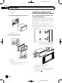
Installing this product 26
– Installation notes 26
– Parts supplied 27
– Before installing this product 27
– Installation with the holder 27
– Installation using the screw holes on
the side of this product 28
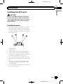
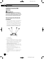
Installing the GPS aerial 29
– Installation notes 29
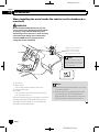
– When installing the aerial inside the
vehicle (on the dashboard or rear
shelf) 30
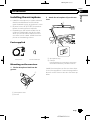
Installing the microphone 31
– Parts supplied 31
– Mounting on the sun visor 31
– Installation on the steering column 32
– Adjusting the microphone angle 32
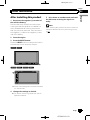
After installation
After installing this product 33
<CRD4952-B>2
Contents
Engb
2

Black plate (3,1)
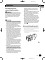
Your new product and this
manual
! The navigation features of this product
(and the rear view camera option if pur-
chased) are intended solely to aid you in
the operation of your vehicle. It is not a sub-
stitute for your attentiveness, judgement
and care when driving.
! Never use this product to route to hospi-
tals, police stations, or similar facilities in
an emergency. Please call the appropriate
emergency number.
! Do not operate this product, any applica-
tions, or the rear view camera option (if pur-
chased) if doing so will divert your attention
in any way from the safe operation of your
vehicle. Always observe safe driving rules
and follow all existing traffic regulations. If
you experience difficulty in operating this
product or reading the display, park your
vehicle in a safe location and apply the
handbrake before making the necessary
adjustments.
! This manual explains how to install this
product in your vehicle. Operation of this
product is explained in the separate man-
uals.
! Do not install this product where it may (i)
obstruct the driver’s vision, (ii) impair the
performance of any of the vehicle’s operat-
ing systems of safety features, including
airbags, hazard lamp buttons, or (iii) impair
the driver’s ability to safely operate the vehi-
cle. In some cases, it may not be possible
to install this product because of the vehi-
cle type or the shape of the vehicle interior.
! Model icons shown in this manual indicate
that the description is intended for the
models indicated by the icons.
If the following icon is shown, the descrip-
tion is applied only to the model shown.
e.g.)
F88DAB
! The graphical symbol placed on
the product means direct current.
Important safeguards
WARNING
Pioneer does not recommend that you install
this product yourself. This product is de-
signed for professional installation only. We
recommend that only authorised Pioneer ser-
vice personnel, who have special training
and experience in mobile electronics, set up
and install this product. NEVER SERVICE
THIS PRODUCT YOURSELF. Installing or
servicing this product and its connecting
cables may expose you to the risk of electric
shock or other hazards, and can cause da-
mage to this product that is not covered by
warranty.
! Read this manual fully and carefully before
installing this product.
! Keep this manual handy for future refer-
ence.
! Pay close attention to all warnings in this
manual and follow the instructions care-
fully.
! This product may in certain circumstances
display inaccurate position of your vehicle,
the distance of objects shown on the
screen, and compass directions. In addi-
tion, the system has certain limitations, in-
cluding the inability to identify one-way
streets, temporary traffic restrictions and
potentially unsafe driving areas. Please ex-
ercise your own judgement in the light of
actual driving conditions.
! As with any accessory in your vehicle’s in-
terior, this product should not divert your
attention from the safe operation of your
vehicle as it may result in serious injury or
death. If you experience difficulty in operat-
ing the system or reading the display,
please make adjustments while safely
parked.
! Please remember to wear your seat belt at
all times while operating your vehicle. If
you are in an accident, your injuries can be
considerably more severe if your seat belt
is not properly fastened.
<CRD4952-B>3
Engb
3
English
Section
01
Precautions

Black plate (4,1)
! Certain country and government laws may
prohibit or restrict the placement and use
of this product in your vehicle. Please com-
ply with all applicable laws and regulations
regarding the use, installation and opera-
tion of this product.
<CRD4952-B>4
Engb
4
Section
01
Precautions

Black plate (5,1)
Precautions before
connecting the system
WARNING
Do not take any steps to tamper with or dis-
able the handbrake interlock system which
is in place for your protection. Tampering
with or disabling the handbrake interlock
system could result in serious injury or
death.
CAUTION
! If you decide to perform the installation
yourself, and have special training and ex-
perience in the mobile electronics instal-
lations, please carefully follow all of the
steps in the installation manual.
! Secure all wiring with cable clamps or
electrical tape. Do not allow any bare wir-
ing to remain exposed.
! Do not directly connect the yellow lead of
this product to the vehicle battery. If the
lead is directly connected to the battery,
engine vibration may eventually cause
the insulation to fail at the point where
the wire passes from the passenger com-
partment into the engine compartment. If
the yellow lead’s insulation tears as a re-
sult of contact with metal parts, short-cir-
cuiting can occur, resulting in
considerable danger.
! It is extremely dangerous to allow cables
to become wound around the steering col-
umn or gearstick. Be sure to install this
product, its cables, and wiring away in
such so that they will not obstruct or hin-
der driving.
! Make sure that the cables and wires will
not interfere with or become caught in
any of the vehicle’s moving parts, espe-
cially the steering wheel, gearstick, hand-
brake, sliding seat tracks, doors, or any of
the vehicle’s controls.
! Do not route wires where they will be ex-
posed to high temperatures. If the insula-
tion heats up, wires may become
damaged, resulting in a short circuit or
malfunction and permanent damage to
the product.
! Do not cut the GPS aerial cable to shorten
it or use an extension to make it longer.
Altering the aerial cable could result in a
short circuit or malfunction.
! Do not shorten any leads. If you do, the
protection circuit (fuse holder, fuse resis-
tor or filter, etc.) may fail to work properly.
! Never feed power to other electronic pro-
ducts by cutting the insulation of the
power supply lead of this product and tap-
ping into the lead. The current capacity of
the lead will be exceeded, causing over-
heating.
Before installing this product
! Use this product with a 12-volt battery and
negative earthing only. Failure to do so may
result in a fire or malfunction.
! To avoid shorts in the electrical system, be
sure to disconnect the (–) battery cable be-
fore installation.
<CRD4952-B>5
Engb
5
English
Section
02
Connection

Black plate (6,1)
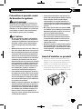
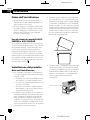
To prevent damage
WARNING
! Use speakers over 50 W (maximum input
power) and between 4 W to 8 W (impe-
dance value). Do not use 1 W to 3 W speak-
ers for this product.
! The black lead is earth. Please earth this
lead separately from the earth of high-cur-
rent products such as power amps. Do not
earth more than one product together
with the earth from another product. For
example, you must separately earth any
amp unit away from the earth of this pro-
duct. Connecting earths together can
cause a fire and/or damage the products if
their earths became detached.
! When replacing the fuse, be sure to only
use a fuse of the rating prescribed on this
product.
! When disconnecting a connector, pull the
connector itself. Do not pull the lead, as
you may pull it out of the connector.
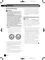
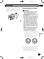
! This product cannot be installed in a vehi-
cle without ACC (accessory) position on
the ignition switch.
A
C
C
O
N
S
T
A
R
T
O
F
F
O
N
S
T
A
R
T
O
F
F
ACC position No ACC position
! To avoid short-circuiting, cover the discon-
nected lead with insulating tape. It is espe-
cially important to insulate all unused
speaker leads, which if left uncovered may
cause a short circuit.
! Attach the connectors of the same colour
to the corresponding coloured port, i.e.,
blue connector to the blue port, black to
black, etc.
! Refer to the owner’s manual for details on
connecting the power amp and other units,
then make connections accordingly.
! Since a unique BPTL circuit is employed,
do not directly earth the * side of the
speaker lead or connect the * side of an-
other side of the speaker lead together. Be
sure to connect the * side of the speaker
lead to the * side of the speaker lead on
this product.
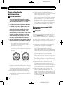
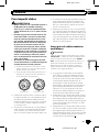
Notice for the blue/white lead
Important
When this product is in “Power OFF” mode, the
control signal is also turned off. If “Power OFF”
mode is cancelled, the control signal is output
again and the aerial is extended with the auto aer-
ial function (if the aerial is being used). Be careful
so that the extended aerial does not come into
contact with any obstacles.
! When the ignition switch is turned on (ACC
ON), a control signal is output through the
blue/white lead. Connect to an external
power amp’s system remote control term-
inal, the auto-aerial relay control terminal,
or the aerial booster power control terminal
(max. 300 mA 12 V DC). The control signal
is output through the blue/white lead, even
if the audio source is switched off.
! Be sure not to use this lead as the power
supply lead for the external power amps.
Such connection could cause excessive
current drain and malfunction.
! Be sure not to use this lead as the power
supply lead for the auto-aerial or aerial
booster. Such connection could cause ex-
cessive current drain and malfunction.
<CRD4952-B>6
Engb
6
Section
02
Connection

Black plate (7,1)
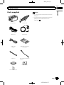
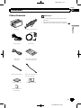
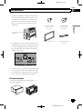
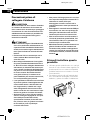
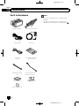
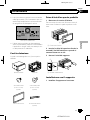
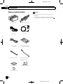
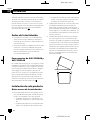
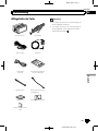
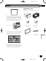
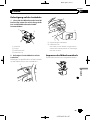
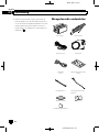
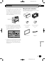
Parts supplied
This product Power cord
GPS aerial Microphone
USB cable
(2 pcs.)
USB cable identifica-
tion labels
Lock tie*1 Vehicle Bus conversion
cable*2
Metal sheet Clamp (3 pcs.)
Double-sided tape
Notes
! (*1) These parts are supplied with AVIC-
F88DAB.
! (*2) These parts are supplied with AVIC-
F88DAB, AVIC-F80DAB and AVIC-
F980DAB.
<CRD4952-B>7
Engb
7
English
Section
02
Connection

Black plate (8,1)
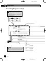
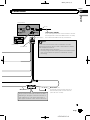
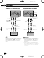
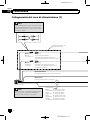
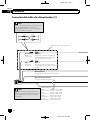
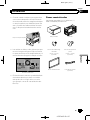
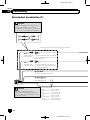
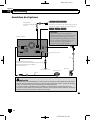
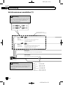
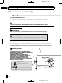
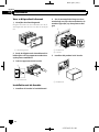
Connecting the power cord (1)
Depending on the types of vehicles, the
function of *2 and *4 may be different. In this
case, be sure to connect *1 to *4 and *3 to *2
as shown in the figure.
Connect leads of the
same colour to each other.
Yel lo w (*2)
Back-up
(or accessory)
Red (*4)
Accessory
(or back-up)
Yel lo w (*1)
To terminal supplied with
power regardless of ignition
switch position.
Red (*3)
To electric terminal controlled by
ignition switch (12 V DC) ON/OFF.
Orange/white
To lighting switch terminal.
Black (earth)
To vehicle (metal) body.
Note
In some vehicles, the ISO connector may be divided
into two. In this case, be sure to connect to both
connectors.
Note
*2 *1
*4 *3
ISO connector
Speaker leads
White: Front left
White/black: Front left
Grey: Front right
Grey/black: Front right
Green: Rear left
Green/black: Rear left
Violet: Rear right
Violet/black: Rear right
<CRD4952-B>8
Engb
8
Section
02
Connection

Black plate (9,1)
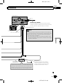
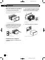
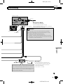
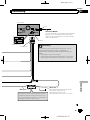
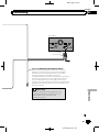
Note
The pin position of the ISO connector will differ
depending on the types of vehicles. Connect *5
and *6 when Pin 5 is an aerial control type. In
other types of vehicles, never connect *5 and *6.
Yellow/black (MUTE)
If you use equipment with a mute function, connect
that equipment to the Audio Mute lead. If not, keep
the Audio Mute lead free of any connections.
Power cord
Audio source will be set to mute or attenuate, while the
following sounds will not be muted or attenuated. For details,
refer to Operation Manual.
— Voice guidance of the navigation
— Incoming ringtone and incoming voice of the mobile phone
that is connected to this product via Bluetooth wireless
technology
This product
14 cm
Fuse (10 A)
Blue/white (*5)
Blue/white (*6)
To auto-aerial relay control terminal or
aerial booster power control terminal
(max. 300 mA 12 V DC).
Power supply
<CRD4952-B>9
Engb
9
English
Section
02
Connection

Black plate (10,1)
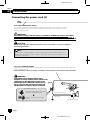
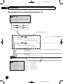
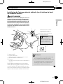
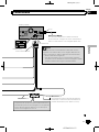
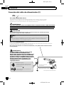
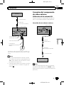
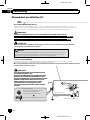
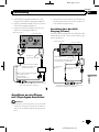
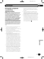
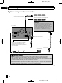
Connecting the power cord (2)
Pink (CAR SPEED SIGNAL INPUT)
This product is connected here to detect the distance the vehicle travels. Always connect the
vehicle’s speed detection circuit. Failure to make this connection will increase errors in the
vehicle’s location display.
LIGHT GREEN LEAD AT POWER CONNECTOR IS
DESIGNED TO DETECT PARKED STATUS AND MUST BE
CONNECTED TO THE POWER SUPPLY SIDE OF THE
HANDBRAKE SWITCH. IMPROPER CONNECTION OR
USE OF THIS LEAD MAY VIOLATE APPLICABLE LAW
AND MAY RESULT IN SERIOUS INJURY OR DAMAGE.
Light green (PARKING BRAKE)
Used to detect the ON/OFF status of the handbrake. This lead must be connected to the power supply side
of the handbrake switch.
If this connection is made incorrectly or omitted, certain functions of this product will be unusable.
Power supply side
Earth side
Handbrake switch
Connection method
Clamp the lead of the power supply
side of the handbrake switch.
Clamp firmly with needle-nosed
pliers.
The position of the speed detection circuit and the position of the handbrake switch vary
depending on the vehicle model. For details, consult your authorised Pioneer dealer or an
installation professional.
Note
WARNING
CAUTION
It is strongly suggested that the speed pulse wire be connected for accuracy of navigation
and better performance.
IMPROPER CONNECTION MAY RESULT IN SERIOUS DAMAGE OR INJURY INCLUDING
ELECTRICAL SHOCK, AND INTERFERENCE WITH THE OPERATION OF THE VEHICLE´S
ANTILOCK BRAKING SYSTEM, AUTOMATIC GEARBOX AND SPEEDOMETER INDICATION.
WARNING
<CRD4952-B>10
Engb
10
Section
02
Connection

Black plate (11,1)
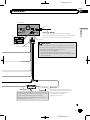
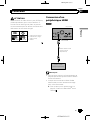
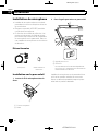
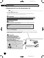
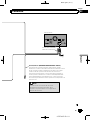
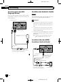
Violet/white (REVERSE-GEAR SIGNAL INPUT)
This is connected so that this product can detect whether
the vehicle is moving forwards or backwards. Connect the
violet/white lead to the lead whose voltage changes when
the reverse gear is engaged. Unless connected, the sensor
may not detect your vehicle travelling forward/backward
properly, and thus the position of your vehicle detected by
the sensor may be misaligned from the actual position.
When you use a rear view camera, please make
sure to connect this lead. Otherwise you cannot
switch to the rear view camera picture.
This product
Note
Power cord
Power supply
<CRD4952-B>11
Engb
11
English
Section
02
Connection

Black plate (12,1)
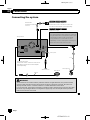
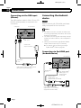
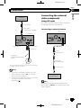
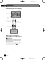
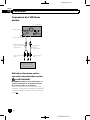
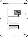
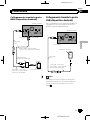
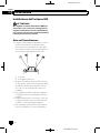
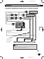
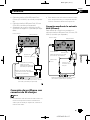
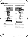
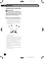
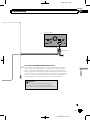
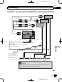
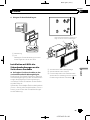
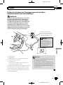
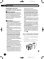
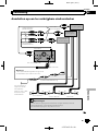
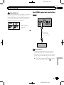
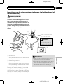
Connecting the system
This product
Wired remote input
Please refer to the instruction manual for
the Hard-wired remote control adapter
(sold separately).
3.55 m
Aerial jack
Vehicle aerial
Microphone
3 m
Vehicle Bus
conversion cable
15.8 cm
WARNING
Vehicle Bus adapter input
Please refer to the instruction manual for
the Vehicle Bus adapter (sold separately).
· To avoid the risk of accident and the potential violation of applicable laws, this product should
never be used while the vehicle is being driven except for navigation purposes. And, also rear
displays should not be in a location where it is a visible distraction to the driver.
· In some countries, the viewing of images on a display inside a vehicle even by persons other than
the driver may be illegal. Where such regulations apply they must be obeyed and this product’s
video source should not be used.
GPS aerial
CAUTION:
For improved Digital Radio reception, make sure
a Digital Radio aerial with phantom power input
(active type) is used. Pioneer recommends
using AN-DAB1 or CA-AN-DAB.001 (sold
separately). Current consumption of the Digital
Radio aerial should be 100 mA or less.
DAB aerial input
F80DAB F980DABF88DAB
F80DAB F980DABF88DAB
<CRD4952-B>12
Engb
12
Section
02
Connection

Black plate (13,1)
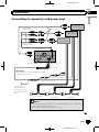
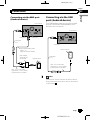
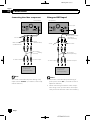
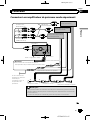
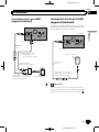
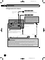
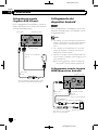
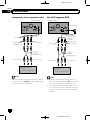
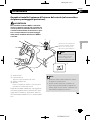
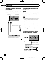
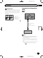
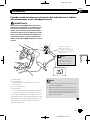
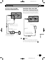
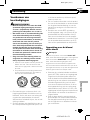
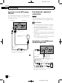
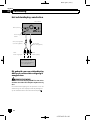
Connecting to separately sold power amp
System remote control
Power cord
Blue/white
Power amp
(sold separately)
Power amp
(sold separately)
Power amp
(sold separately)
Front speaker
Rear speaker
Subwoofer
RCA
cables
(sold separately)
This product
15 cm
Rear outputs
(REAR OUTPUT)
Front outputs
(FRONT OUTPUT)
To system control terminal of the power amp
(max. 300 mA 12 V DC).
White, Red (SWL, SWR)
Notes
· You can change the RCA output of the subwoofer depending on your subwoofer
system. (Refer to Operation Manual.)
· The subwoofer output of this product is monaural.
If your vehicle is
equipped with an
auto-aerial, connect
this lead to a power
amp.
Power supply
<CRD4952-B>13
Engb
13
English
Section
02
Connection

Black plate (14,1)
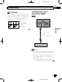
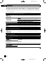
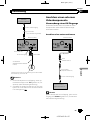
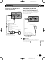
Connecting an iPod / iPhone or an Android device
Find your device and the function you want to operate from the list below, and refer to the page for the connection.
p Depending on the device, some functions may not be available.
iPhone (5, 5c, 5s, 6, 6 Plus)/iPod touch (5th generation)
iPod (audio)
Apple CarPlay
AVICSYNC App
Refer to Connecting via the USB port (iPhone) on page 15.
AppRadio Mode
AVICSYNC App
F88DAB
Refer to Connecting via the HDMI port (iPhone) on page 16.
F80DAB F980DAB
F980BT
F9880DAB
F9880BT
Refer to Connecting via the RGB input (iPhone) on page 16.
iPhone 3GS/iPod touch (2nd, 3rd generation)/iPod classic (80GB, 160GB)/iPod nano (3rd, 4th, 5th, 6th gen-
eration)
iPod (audio)
iPod (video)
Refer to Connecting via the AUX input (iPhone) on page 17.
iPhone (4, 4s)/iPod touch (4th generation)
iPod (audio)
iPod (video)
AppRadio Mode
AVICSYNC App
Refer to Connecting via the RGB input (iPhone) on page 18.
iPod nano (7th generation)
iPod (audio) Refer to Connecting via the USB port (iPhone) on page 15.
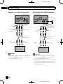
Android device
F88DAB
AppRadio Mode
HDMI port
Refer to Connecting via the HDMI port (Android device) on page 18.
MHL port
Refer to Connecting via the MHL port (Android device) on page 19.
AVICSYNC App
F88DAB
F80DAB
Android Auto
Refer to Connecting via the USB port (Android device) on page 19.
AVICSYNC App
<CRD4952-B>14
Engb
14
Section
02
Connection

Black plate (15,1)
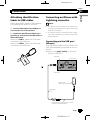
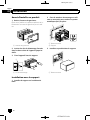
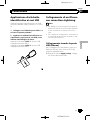
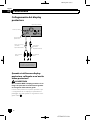
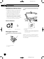
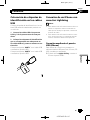
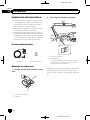
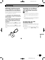
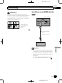
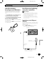
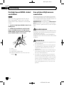
Attaching identification
labels to USB cables
Attach identification labels to USB cables be-
fore installing this product in a vehicle.
1 Connect USB cables to the USB port 1
and 2 on the rear of this product.
2 Attach the identification labels corre-
sponding to each port to the USB cables as
illustrated below.
Attach the “PORT 1” label to the USB cable
connected to the USB port 1.
Attach the “PORT 2” label to the USB cable
connected to the USB port 2.
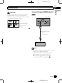
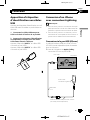
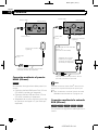
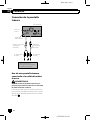
Connecting an iPhone with
Lightning connector
Notes
! For details on how to connect an external de-
vice using a separately sold cable, refer to the
manual for the cable.
! For details concerning the connection, opera-
tions and compatibility of iPhone, refer to Op-
eration Manual.
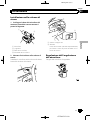
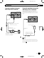
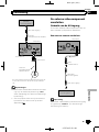
Connecting via the USB port
(iPhone)
The USB interface cable for iPod / iPhone (CD-
IU52) (sold separately) is required for the con-
nection.
p When using Apple CarPlay, connect the
iPhone to USB port 1.
This product
USB port 1
iPhone with
Lightning connector
USB cable
1.5 m
USB interface cable for iPod / iPhone
(CD-IU52) (sold separately)
USB port 2
<CRD4952-B>15
Engb
15
English
Section
02
Connection

Black plate (16,1)
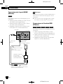
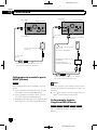
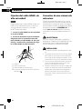
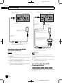
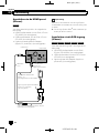
Connecting via the HDMI port
(iPhone)
F88DAB
The following cables are required for the con-
nection.
! HDMI interface cable for iPod / iPhone
(CD-IH202) (sold separately)
! USB interface cable for iPod / iPhone (CD -
IU52) (sold separately)
! Lightning Digital AV Adapter (Apple Inc.
products) (sold separately)
This product
USB port 1
USB interface cable for iPod / iPhone
(CD-IU52) (sold separately)
iPhone with
Lightning connector
High Speed HDMI
®
Cable
(Type A - A)
(supplied with CD-IH202)
HDMI port
Lightning Digital AV Adapter
(Apple Inc. products)
(sold separately)
USB cable
1.5 m
Note
When you connect the High Speed HDMI
®
Cable,
use the lock tie to fix it securely.
= For details, refer to Securing the High Speed
HDMI
®
Cable on page 20.
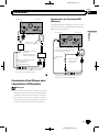
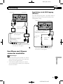
Connecting via the RGB input
(iPhone)
F80DAB F980DAB F980BT
F9880DAB
F9880BT
The following cables are required for the con-
nection.
! VGA/USB interface cable for iPod / iPhone
(CD-IV202AV) (sold separately)
! USB interface cable for iPod / iPhone (CD -
IU52) (sold separately)
! Lightning to VGA Adapter (Apple Inc. pro-
ducts) (sold separately)
<CRD4952-B>16
Engb
16
Section
02
Connection

Black plate (17,1)
Lightning to VGA Adapter
(Apple Inc. products)
(sold separately)
This product
USB port 1
RGB input
iPhone with
Lightning connector
USB interface cable for iPod / iPhone
(CD-IU52) (sold separately)
VGA/USB interface cable
for iPod / iPhone
(CD-IV202AV) (sold separately)
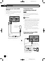
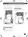
Connecting an iPhone with
30-pin connector
Notes
! For details on how to connect an external de-
vice using a separately sold cable, refer to the
manual for the cable.
! For details concerning the connection, opera-
tions and compatibility of iPhone, refer to Op-
eration Manual.
Connecting via the AUX input
(iPhone)
The USB interface cable for iPod / iPhone (CD-
IU201V) (sold separately) is required for the
connection.
This product
USB interface cable for iPod / iPhone
(CD-IU201V) (sold separately)
USB cable
1.5 m
iPhone with
30-pin connector
AUX input
USB port 1
USB port 2
Mini-jack extension cable
(supplied with CD-IU201V)
<CRD4952-B>17
Engb
17
English
Section
02
Connection

Black plate (18,1)
Connecting via the RGB input
(iPhone)
The USB interface cable for iPod / iPhone (CD-
IU201S) (sold separately) is required for the
connection.
USB cable
1.5 m
USB interface cable for iPod / iPhone
(CD-IU201S) (sold separately)
This product
USB port 1
RGB input
iPhone with
30-pin connector
Connecting the Android
™
device
F88DAB
App Connectivity Kit (CD-AH200) (sold sepa-
rately) is required for the connection.
Notes
! For details on how to connect an external de-
vice using a separately sold cable, refer to the
manual for the cable.
! For details concerning the connection and op-
erations of Android device, refer to Operation
Manual.
! When you connect the High Speed HDMI
®
Cable, use the lock tie to fix it securely.
= For details, refer to Securing the High
Speed HDMI
®
Cable on page 20.
Connecting via the HDMI port
(Android device)
USB cable
1.5 m
This product
Android device
USB port 2
HDMI port
High Speed HDMI
®
Cable (Type A - A)
(supplied with
CD-AH200)
USB - micro USB cable
(Type USB A - micro USB B)
(supplied with CD-AH200)
Adapter cable
(HDMI Type A - D)
(supplied with CD-AH200)
<CRD4952-B>18
Engb
18
Section
02
Connection

Black plate (19,1)
Connecting via the MHL port
(Android device)
USB cable
1.5 m
This product
Android device
USB port 2
HDMI port
High Speed HDMI
®
Cable
(Type A - A)
(supplied with CD-AH200)
USB - micro USB cable
(Type USB A - micro USB B)
(supplied with CD-AH200)
MHL adapter
(supplied with
CD-AH200)
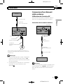
Connecting via the USB
port (Android device)
The USB interface cable for use with Android
devices (CD-MU200) (sold separately) is re-
quired for the connection.
USB cable
1.5 m
USB - micro USB cable
(Type USB A - micro USB B)
(supplied with CD-MU200)
This product
Android device
USB port 2
Note
For details on how to connect an external device
using a separately sold cable, refer to the manual
for the cable.
<CRD4952-B>19
Engb
19
English
Section
02
Connection

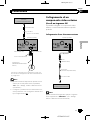
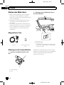
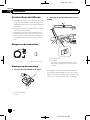
Black plate (20,1)
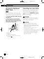
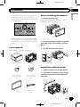
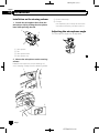
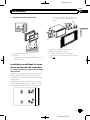
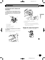
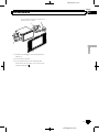
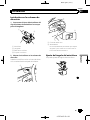
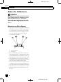
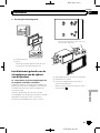
Securing the High Speed
HDMI
®
Cable
F88DAB
Be sure to fix the High Speed HDMI
®
Cable
with the lock tie, when you connect the exter-
nal device with the High Speed HDMI
®
Cable.
1 Insert the High Speed HDMI
®
Cable into
the HDMI port.
2 Wrap the lock tie around the hook
above the HDMI port and the High Speed
HDMI
®
Cable, and then tighten it to secure
the High Speed HDMI
®
Cable.
1
2
3
1 Hook
2 Lock tie
3 High Speed HDMI
®
Cable
p Do not tighten up the lock tie more than
necessary.
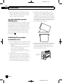
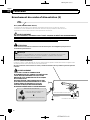
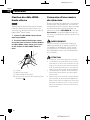
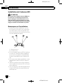
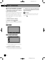
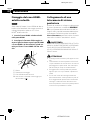
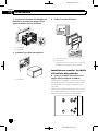
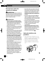
Connecting a rear view camera
When this product is used with a rear view
camera, it is possible to automatically switch
from the video to rear view image when the
gearstick is moved to REVERSE (R). Camera
View mode also allows you to check what is
behind you while driving.
WARNING
USE INPUT ONLY FOR REVERSE OR MIRROR
IMAGE REAR VIEW CAMERA. OTHER USE MAY
RESULT IN INJURY OR DAMAGE.
CAUTION
! The screen image may appear reversed.
! The rear view camera is used as an aid to
keep an eye on trailers, or backing into a tight
parking spot. Do not use this function for en-
tertainment purposes.
! Objects in rear view may appear closer or
more distant than in reality.
! Please note that the image area shown by the
rear view camera may differ slightly when full-
screen images are displayed when backing
and when checking the rear of the vehicle
while moving forward.
<CRD4952-B>20
Engb
20
Section
02
Connection
La pagina sta caricando ...
La pagina sta caricando ...
La pagina sta caricando ...
La pagina sta caricando ...
La pagina sta caricando ...
La pagina sta caricando ...
La pagina sta caricando ...
La pagina sta caricando ...
La pagina sta caricando ...
La pagina sta caricando ...
La pagina sta caricando ...
La pagina sta caricando ...
La pagina sta caricando ...
La pagina sta caricando ...
La pagina sta caricando ...
La pagina sta caricando ...
La pagina sta caricando ...
La pagina sta caricando ...
La pagina sta caricando ...
La pagina sta caricando ...
La pagina sta caricando ...
La pagina sta caricando ...
La pagina sta caricando ...
La pagina sta caricando ...
La pagina sta caricando ...
La pagina sta caricando ...
La pagina sta caricando ...
La pagina sta caricando ...
La pagina sta caricando ...
La pagina sta caricando ...
La pagina sta caricando ...
La pagina sta caricando ...
La pagina sta caricando ...
La pagina sta caricando ...
La pagina sta caricando ...
La pagina sta caricando ...
La pagina sta caricando ...
La pagina sta caricando ...
La pagina sta caricando ...
La pagina sta caricando ...
La pagina sta caricando ...
La pagina sta caricando ...
La pagina sta caricando ...
La pagina sta caricando ...
La pagina sta caricando ...
La pagina sta caricando ...
La pagina sta caricando ...
La pagina sta caricando ...
La pagina sta caricando ...
La pagina sta caricando ...
La pagina sta caricando ...
La pagina sta caricando ...
La pagina sta caricando ...
La pagina sta caricando ...
La pagina sta caricando ...
La pagina sta caricando ...
La pagina sta caricando ...
La pagina sta caricando ...
La pagina sta caricando ...
La pagina sta caricando ...
La pagina sta caricando ...
La pagina sta caricando ...
La pagina sta caricando ...
La pagina sta caricando ...
La pagina sta caricando ...
La pagina sta caricando ...
La pagina sta caricando ...
La pagina sta caricando ...
La pagina sta caricando ...
La pagina sta caricando ...
La pagina sta caricando ...
La pagina sta caricando ...
La pagina sta caricando ...
La pagina sta caricando ...
La pagina sta caricando ...
La pagina sta caricando ...
La pagina sta caricando ...
La pagina sta caricando ...
La pagina sta caricando ...
La pagina sta caricando ...
La pagina sta caricando ...
La pagina sta caricando ...
La pagina sta caricando ...
La pagina sta caricando ...
La pagina sta caricando ...
La pagina sta caricando ...
La pagina sta caricando ...
La pagina sta caricando ...
La pagina sta caricando ...
La pagina sta caricando ...
La pagina sta caricando ...
La pagina sta caricando ...
La pagina sta caricando ...
La pagina sta caricando ...
La pagina sta caricando ...
La pagina sta caricando ...
La pagina sta caricando ...
La pagina sta caricando ...
La pagina sta caricando ...
La pagina sta caricando ...
La pagina sta caricando ...
La pagina sta caricando ...
La pagina sta caricando ...
La pagina sta caricando ...
La pagina sta caricando ...
La pagina sta caricando ...
La pagina sta caricando ...
La pagina sta caricando ...
La pagina sta caricando ...
La pagina sta caricando ...
La pagina sta caricando ...
La pagina sta caricando ...
La pagina sta caricando ...
La pagina sta caricando ...
La pagina sta caricando ...
La pagina sta caricando ...
La pagina sta caricando ...
La pagina sta caricando ...
La pagina sta caricando ...
La pagina sta caricando ...
La pagina sta caricando ...
La pagina sta caricando ...
La pagina sta caricando ...
La pagina sta caricando ...
La pagina sta caricando ...
La pagina sta caricando ...
La pagina sta caricando ...
La pagina sta caricando ...
La pagina sta caricando ...
La pagina sta caricando ...
La pagina sta caricando ...
La pagina sta caricando ...
La pagina sta caricando ...
La pagina sta caricando ...
La pagina sta caricando ...
La pagina sta caricando ...
La pagina sta caricando ...
La pagina sta caricando ...
La pagina sta caricando ...
La pagina sta caricando ...
La pagina sta caricando ...
La pagina sta caricando ...
La pagina sta caricando ...
La pagina sta caricando ...
La pagina sta caricando ...
La pagina sta caricando ...
La pagina sta caricando ...
La pagina sta caricando ...
La pagina sta caricando ...
La pagina sta caricando ...
La pagina sta caricando ...
La pagina sta caricando ...
La pagina sta caricando ...
La pagina sta caricando ...
La pagina sta caricando ...
La pagina sta caricando ...
La pagina sta caricando ...
La pagina sta caricando ...
La pagina sta caricando ...
La pagina sta caricando ...
La pagina sta caricando ...
La pagina sta caricando ...
La pagina sta caricando ...
La pagina sta caricando ...
La pagina sta caricando ...
La pagina sta caricando ...
La pagina sta caricando ...
La pagina sta caricando ...
La pagina sta caricando ...
La pagina sta caricando ...
La pagina sta caricando ...
La pagina sta caricando ...
La pagina sta caricando ...
La pagina sta caricando ...
La pagina sta caricando ...
La pagina sta caricando ...
La pagina sta caricando ...
La pagina sta caricando ...
La pagina sta caricando ...
La pagina sta caricando ...
La pagina sta caricando ...
La pagina sta caricando ...
La pagina sta caricando ...
La pagina sta caricando ...
-
 1
1
-
 2
2
-
 3
3
-
 4
4
-
 5
5
-
 6
6
-
 7
7
-
 8
8
-
 9
9
-
 10
10
-
 11
11
-
 12
12
-
 13
13
-
 14
14
-
 15
15
-
 16
16
-
 17
17
-
 18
18
-
 19
19
-
 20
20
-
 21
21
-
 22
22
-
 23
23
-
 24
24
-
 25
25
-
 26
26
-
 27
27
-
 28
28
-
 29
29
-
 30
30
-
 31
31
-
 32
32
-
 33
33
-
 34
34
-
 35
35
-
 36
36
-
 37
37
-
 38
38
-
 39
39
-
 40
40
-
 41
41
-
 42
42
-
 43
43
-
 44
44
-
 45
45
-
 46
46
-
 47
47
-
 48
48
-
 49
49
-
 50
50
-
 51
51
-
 52
52
-
 53
53
-
 54
54
-
 55
55
-
 56
56
-
 57
57
-
 58
58
-
 59
59
-
 60
60
-
 61
61
-
 62
62
-
 63
63
-
 64
64
-
 65
65
-
 66
66
-
 67
67
-
 68
68
-
 69
69
-
 70
70
-
 71
71
-
 72
72
-
 73
73
-
 74
74
-
 75
75
-
 76
76
-
 77
77
-
 78
78
-
 79
79
-
 80
80
-
 81
81
-
 82
82
-
 83
83
-
 84
84
-
 85
85
-
 86
86
-
 87
87
-
 88
88
-
 89
89
-
 90
90
-
 91
91
-
 92
92
-
 93
93
-
 94
94
-
 95
95
-
 96
96
-
 97
97
-
 98
98
-
 99
99
-
 100
100
-
 101
101
-
 102
102
-
 103
103
-
 104
104
-
 105
105
-
 106
106
-
 107
107
-
 108
108
-
 109
109
-
 110
110
-
 111
111
-
 112
112
-
 113
113
-
 114
114
-
 115
115
-
 116
116
-
 117
117
-
 118
118
-
 119
119
-
 120
120
-
 121
121
-
 122
122
-
 123
123
-
 124
124
-
 125
125
-
 126
126
-
 127
127
-
 128
128
-
 129
129
-
 130
130
-
 131
131
-
 132
132
-
 133
133
-
 134
134
-
 135
135
-
 136
136
-
 137
137
-
 138
138
-
 139
139
-
 140
140
-
 141
141
-
 142
142
-
 143
143
-
 144
144
-
 145
145
-
 146
146
-
 147
147
-
 148
148
-
 149
149
-
 150
150
-
 151
151
-
 152
152
-
 153
153
-
 154
154
-
 155
155
-
 156
156
-
 157
157
-
 158
158
-
 159
159
-
 160
160
-
 161
161
-
 162
162
-
 163
163
-
 164
164
-
 165
165
-
 166
166
-
 167
167
-
 168
168
-
 169
169
-
 170
170
-
 171
171
-
 172
172
-
 173
173
-
 174
174
-
 175
175
-
 176
176
-
 177
177
-
 178
178
-
 179
179
-
 180
180
-
 181
181
-
 182
182
-
 183
183
-
 184
184
-
 185
185
-
 186
186
-
 187
187
-
 188
188
-
 189
189
-
 190
190
-
 191
191
-
 192
192
-
 193
193
-
 194
194
-
 195
195
-
 196
196
-
 197
197
-
 198
198
-
 199
199
-
 200
200
-
 201
201
-
 202
202
-
 203
203
-
 204
204


Mode AVIC F80 DAB Manuale utente
- Categoria
- Microfoni
- Tipo
- Manuale utente
in altre lingue
- français: Mode AVIC F80 DAB Manuel utilisateur
- español: Mode AVIC F80 DAB Manual de usuario
- Deutsch: Mode AVIC F80 DAB Benutzerhandbuch
- Nederlands: Mode AVIC F80 DAB Handleiding
Documenti correlati


Altri documenti
-
Pioneer AVH-X8800BT Manuale del proprietario
-
Pioneer AVH-X8700BT Guida d'installazione
-
Pioneer AVIC Z7210 DAB Guida d'installazione
-
-
Pioneer AVIC-F80DAB-C Manuale utente
-
Pioneer CD-IV202AV Manuale utente
-
Pioneer SPH-DA02 Manuale utente
-
-
-