Hangar 9 HAN2370 Manuale del proprietario
- Categoria
- Giocattoli telecomandati
- Tipo
- Manuale del proprietario

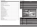
Tiger 30cc
Instruction Manual
Bedienungsanleitung
Manuel d’utilisation
Manuale di Istruzioni

2EN
NOTICE
All instructions, warranties and other collateral documents are subject to change at the sole discretion of Horizon
Hobby, LLC. For up-to-date product literature, visit horizonhobby.com or www.towerhobbies.com and click on the
support or resources tab for this product.
Age Recommendation: Not For Children Under 14 Years. This Is Not A Toy.
SAFETY WARNINGS AND PRECAUTIONS
Read and follow all instructions and safety precautions before use. Improper use can result in fi re, serious injury and
damage to property.
Components
Use only with compatible components. Should any compatibility questions exist, please refer to the product
instructions, component instructions or contact the appropriate Horizon Hobby offi ce.
Flight
Fly only in open areas to ensure safety. It is recommended fl ying be done at radio control fl ying fi elds. Consult local
ordinances before choosing a fl ying location.
Propeller
Always keep loose items that can become entangled in the propeller away from the prop. This includes loose clothing
or other objects such as pencils and screwdrivers. Keep your hands away from the propeller as injury can occur.
Batteries
Always follow the manufacturer’s instructions when using and disposing of any batteries. Mishandling of Li-Po
batteries can result in fi re causing serious injury and damage.
Small Parts
This kit includes small parts and should not be left unattended near children as choking and serious injury could result.
MEANING OF SPECIAL LANGUAGE
The following terms are used throughout the product literature to indicate various levels of potential harm when
operating this product:
WARNING: Procedures, which if not properly followed, create the probability of property damage, collateral damage,
and serious injury OR create a high probability of superfi cial injury.
CAUTION: Procedures, which if not properly followed, create the probability of physical property damage AND a
possibility of serious injury.
NOTICE: Procedures, which if not properly followed, create a possibility of physical property damage AND a little or
no possibility of injury.
WARNING: Read the ENTIRE instruction manual to become familiar with the features of the product before
operating. Failure to operate the product correctly can result in damage to the product, personal property and
cause serious injury.
This is a sophisticated hobby product. It must be operated with caution and common sense and requires some basic
mechanical ability. Failure to operate this Product in a safe and responsible manner could result in injury or damage
to the product or other property. This product is not intended for use by children without direct adult supervision. Do
not attempt disassembly, use with incompatible components or augment product in any way without the approval
of Horizon Hobby, LLC. This manual contains instructions for safety, operation and maintenance. It is essential to
read and follow all the instructions and warnings in the manual, prior to assembly, setup or use, in order to operate
correctly and avoid damage or serious injury.
SAFE OPERATING RECOMMENDATIONS
• Inspect your model before every fl ight to ensure it is airworthy.
• Be aware of any other radio frequency user who may present an interference problem.
• Always be courteous and respectful of other users in your selected fl ight area.
• Choose an area clear of obstacles and large enough to safely accomodate your fl ying activity.
• Make sure this area is clear of friends and spectators prior to launching your aircraft.
• Be aware of other activities in the vicinity of your fl ight path that could cause potential confl ict.
• Carefully plan your fl ight path prior to launch.
• Abide by any and all established AMA National Model Aircraft Safety Code.
BEFORE STARTING ASSEMBLY
• Remove parts from bag.
• Inspect fuselage, wing panels, rudder and stabilizer for damage.
• If you fi nd damaged or missing parts, contact your place of purchase.
• Charge transmitter and receiver batteries.
• Center trims and sticks on your transmitter.
• For a computer radio, create a model memory for this particular model.
• Bind your transmitter and receiver, using your radio system’s instructions.
NOTICE: Rebind the radio system once all control throws are set. This will keep the servos from moving to their
endpoints until the transmitter and receiver connect. It will also guarantee the servo reversal settings are saved in the
radio system.
FAA INFORMATION
If you own this product, you may be required to register with the FAA.
For up-to-date information on how to register with the FAA, please visit https://registermyuas.faa.gov/.
For additional assistance on regulations and guidance on UAS usage, visit knowbeforeyoufl y.org/.

3 EN
Tiger 30cc ARF
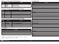
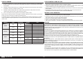
# Required Part # Description
1 DLEG0031 DLE-30cc Gas Rear Carb w/Elec Ig &
1 EFLM4160A Power 160 BL Outrunner Motor, 245Kv
1 EFLM4180A Power 180 BL Outrunner Motor, 195Kv
1 EVOA100 Optical Ignition Kill Switch
1 GPMA1676 Float Set Avistar 30cc/EP Trainer ARF
1 GPMG4795 Rimfi re 1.60 63-62-250 Outrunner Brushless
1 HAN237013 Float Mounting Parts Set:Tiger 30cc
2 KXSB50005S30 F-Tek 5000mAh 5S 18.5V 30C, EC5
1 OSMG1533 GT33 Gas Engine
2 SPMX70006S30 7000mah 6S 22.2V Smart 30C; IC5
OPTIONAL PARTS
Part # Description
HAN237001 Fuselage
HAN237002 Wing Set
HAN237003 Tail Set
HAN237004 Cowling
HAN237005 Canopy Top Hatch
HAN237006 Wheel Pants
HAN237007 Wing Tube
HAN237008 Tailwheel Assy
HAN237009 Decal Set
HAN237010 Main Landing Gear
HAN237011 Wheels
HAN237012 Fuel Tank; 14oz
REPLACEMENT PARTSTABLE OF CONTENTS
Notice ......................................................................................................................................................................2
Meaning of Special Language ..................................................................................................................................2
Safety Warnings and Precautions .............................................................................................................................2
Safe Operating Recommendations ...........................................................................................................................2
Before Starting Assembly .........................................................................................................................................2
FAA Information .......................................................................................................................................................2
Replacement Parts ...................................................................................................................................................3
Optional Parts ..........................................................................................................................................................3
Required for Completion, All Power Options ..............................................................................................................4
Required for Completion, Gas Engine Installation......................................................................................................4
Required for Completion, Electric Motor Installation .................................................................................................4
Required Adhesives .................................................................................................................................................4
Tools Required .........................................................................................................................................................4
Removing Wrinkles ..................................................................................................................................................5
Building Precautions ................................................................................................................................................5
Transportation and Storage ......................................................................................................................................5
Replacement Covering .............................................................................................................................................5
Checking Blind Nuts.................................................................................................................................................5
For the Visually Challenged ......................................................................................................................................5
Aileron Servo Installation .........................................................................................................................................5
Flap Servo Installation (Optional) ..............................................................................................................................9
Wing and Stabilizer Installation ..............................................................................................................................10
Elevator Servo Installation ......................................................................................................................................12
Rudder and Fin Installation.....................................................................................................................................14
Rudder Servo Installation .......................................................................................................................................15
Tail Wheel Installation ............................................................................................................................................15
Main Landing Gear Installation ...............................................................................................................................16
Receiver and Receiver Battery Installation..............................................................................................................17
Electric Motor Box Assembly ..................................................................................................................................18
Electric Motor Installation .......................................................................................................................................20
Gas Engine Installation ...........................................................................................................................................22
Fuel Tank Assembly and Installation .......................................................................................................................25
Cowling and Spinner Installation ............................................................................................................................26
Center of Gravity ....................................................................................................................................................28
Control Throws ......................................................................................................................................................28
Prefl ight Checklist ..................................................................................................................................................29
Daily Flight Checks ................................................................................................................................................29
Limited Warranty ...................................................................................................................................................29
Warranty and Service Contact Information .............................................................................................................30
Instructions for Disposal of WEEE by Users in the European Union ..........................................................................30
Academy of Model Aeronautics National Model Aircraft Safety Code .......................................................................30

4EN
REQUIRED FOR COMPLETION, GAS ENGINE INSTALLATION
REQUIRED FOR COMPLETION, ALL POWER OPTIONS
REQUIRED FOR COMPLETION, ELECTRIC MOTOR INSTALLATION
# Required Part # Description
1 GPMQ4775 Spinner 3-inch Nylon Aluminum White
4 SPMA3002 Heavy-Duty Servo Extension 9-inch
2 SPMA3004 Heavy-Duty Servo Extension 18-inch
1 SPMAR9350 AR9350 9 Channel AS3X Receiver
# Required Part # Description
1 DUB799 Tygon Gas Tubing,3ft Medium
1 DLEG0435* DLE-35RA Rear Exhaust Gas w/Elec Ig
1 HAN116 Fuel Filler with "T" and Overfl ow Fitting
1 MASWM18X10NO1 Master Airscrew 18x10 Maple Propeller
1 SPM9530 Spektrum 3-Wire Switch Harness
2 SPMB2000LPRX 2000mAh 2S 7.4V LiPo Rx Battery
8 SPMSA6380 A6380 H-T/H-S Digital HV Servo
# Required Part # Description
1 APC18010E Electric Propeller, 18 x 10E
1 SPMXCA506 IC5 Battery Series Harness 4-inch 10AW
1 CSE010013100 Talon HV120 ESC 010-0131-00
1 GPMG4796 Rimfi re 1.70 63-62-200 Outrunner
7 SPMSA6380 A6380 H-T/H-S Digital HV Servo
2 SPMX50006S30 5000mah 6S 22.2V Smart 30C; IC5
TOOLS REQUIRED
Description
Box or open end wrench: 10mm, 7/16-inch, 1/2-inch
Clamps
Covering iron
Cutoff wheel for rotary tool
Drill
Drill bit set, metric and english
Epoxy brushes
Felt-tipped pen
Flat blade screwdriver
Flat fi le
Flux paste
Heat gun
Hemostats
Hex wrench set, metric and english
Hobby knife with #11 blade
Hobby scissors
Hobby square
Hook and loop tape
Light machine oil
Low tack tape
Medium grit sandpaper
Mixing cups
Mixing sticks
Pencil
Phillips screwdriver #1, #2
Pin vise
Pliers
Razor saw
Rotary tool
Ruler
Sanding drum for rotary tool
Scissors
Side cutter
Silver solder
Stepped reamer
Toothpicks
Torch or soldering iron
Vise grips
Wire cutter
REQUIRED ADHESIVES
Description
15-minute epoxy
30-minute epoxy
Thin CA
Medium CA
Threadlock, low and high strength
* Use of the DLE-35RA Rear Exhaust engine may require up to 12 ounces (340g) of additional nose weight to properly
balance this model.

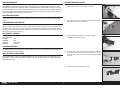
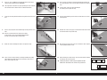
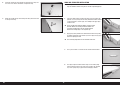
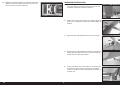
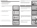
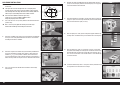
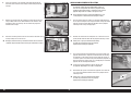
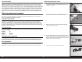
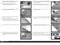
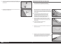
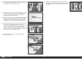
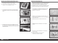
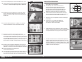
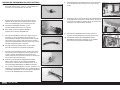
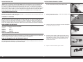
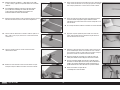
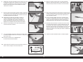
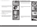
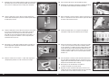
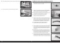
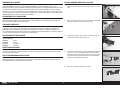
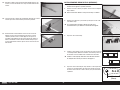
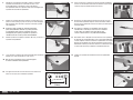
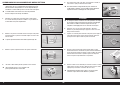
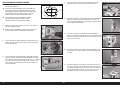
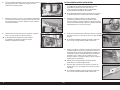
1. Use a hobby knife with a #11 blade to remove the covering on the
top of the wing near the wing root for the servo leads.
5. Prepare both the left and right aileron servos.
3. Install the grommets and eyelets in the servos. Follow any
instructions included with the servo.
2. Use a hobby knife with a #11 blade to remove the covering on the
bottom of the wing for the servo opening.
4. Center the aileron servo using the radio system. Place a servo arm
on the aileron servo perpendicular to the servo centerline. Use side
cutters to remove and arms that may interfere with the operation of
the servo.
AILERON SERVO INSTALLATION
5 EN
Tiger 30cc ARF
REMOVING WRINKLES
The covering of your model may develop wrinkles during shipping. Use a covering iron (HAN101) with a sealing iron
sock (HAN141) to remove them. Start with a lower heat setting and use caution while working around areas where
the colors overlap to prevent separating the colors. It is also advised to use caution around the canopy as it is plastic
and could distort with excessive heat. Avoid using too much heat, which could also separate the colors. Placing a cool
damp cloth on adjacent colors will also help prevent the separation of the colors while removing wrinkles. Only use a
heat gun (HAN100) once the covering iron has been used.
BUILDING PRECAUTIONS
Prepare the work surface prior to beginning the build. The surface should be soft and free of any sharp objects. We
recommend resting the airframe parts on a soft towel or pit mat to prevent scratching or denting the surface of the
aircraft.
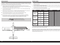
TRANSPORTATION AND STORAGE
When transporting and storing your model, you will need a minimum of 80 inches (2.1m) in length, and 19 inches
(50cm) in height to accommodate the size of the fuselage. We also recommend the use of wing and stabilizer bags to
help protect these surfaces during transport and storage. The control horns and linkages can cause damage to other
surfaces even when placed in storage bags. Always transport and store the wings and stabilizer so the linkages do not
contact other panels to prevent damage.
REPLACEMENT COVERING
Your model is covered with MonoKote® fi lm in the following colors. If repairs are required, order these coverings to
make those repairs.
TOPQ0201 Red
TOPQ0204 White
TOPQ0226 Sapphire Blue
TOPQ0205 Aluminum
CHECKING BLIND NUTS
When building the aircraft, you will be required to thread machine screws into blind nuts. We recommend pre-threading
the screws to make sure the blind nuts are clear of any debris. If the screws do not thread in easily, clear the threads
using the appropriate tap and tap handle.
FOR THE VISUALLY CHALLENGED
A copy of this manual can be found at www.horizonhobby.com under the tab for this particular model. Feel free to
download this manual and use a PDF viewer to zoom in on any text or images that may be in question when building
from the printed manual.

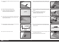
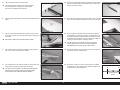
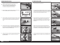
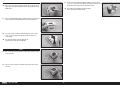
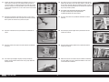
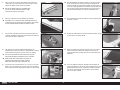
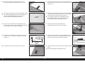
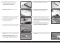
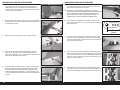
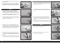
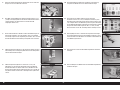
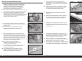
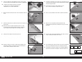
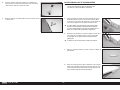
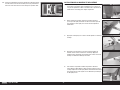
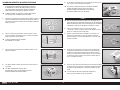
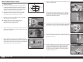
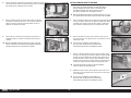
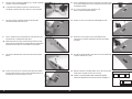
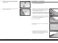
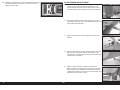
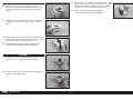
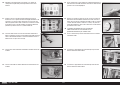
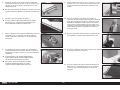
6. Secure an 18-inch (460mm) servo extension to the servo using a
commercially available retainer (SPMA3054).
The length of the extension may vary depending on servo selection.
The extension listed is uitable for the recommended servos.
7. Tie or tape the string located inside the wing to the end of the servo
lead.
9. Route the servo lead through the hole in the top of the wing.
10. Fit the servo in the wing with the servo output toward the leading
edge. Mark the locations for the servo mounting screws using a
pencil, then remove the servo.
8. Use the string to pull the servo lead through the wing and out at the
root.
We left a small amount of the string on the aileron
servo lead so it can be quickly differentiated between
the flap servo lead that will be installed later.
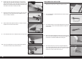
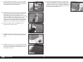
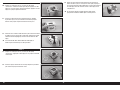
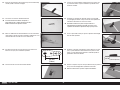
11. Use a pin vise and a 5/64-inch (2mm) drill bit to drill the holes for
the servo mounting screws in the locations marked in the previous
step.
If using a drill, make sure not to drill through
the covering on the top of the wing.
12. Thread a servo mounting screw into each of the holes in the servo
mounting holes.
14. After the CA has fully cured, secure the servo to the cover using the
screws provided with the servo.
15. When mounting the aileron servos, the servo arms will face toward
the wing tips on each wing panel.
Installing the aileron servos facing the opposite direction
allows their connection to the receiver using a Y-Harness.
13. Remove the screws, then apply a small amount of thin CA to harden
the threads made in the previous step.
6EN

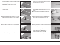
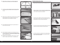
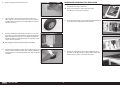
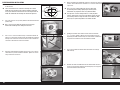
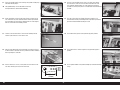
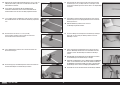
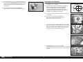
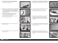
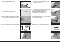
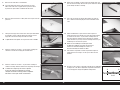
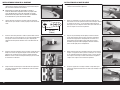
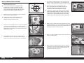
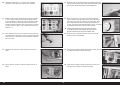
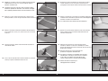
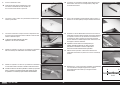
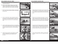
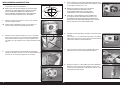
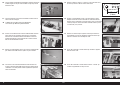
16. Use low-tack tape to hold the aileron/fl ap centered when installing
the linkage.
17. Slide a retainer over the barrel of the clevises.
There are an equal number of threaded clevises
and solder clevises. Make sure to sort the clevises
so they can be used in the correct locations.
19. When attaching the clevis to the servo arm, use the hole that is 5/8
in (16mm) from the center of the servo horn.
20. Attach the clevis to the aileron servo arm.
18. Thread a 4-40 nut on the threaded end of a short pushrod. Thread
the clevis on the pushrod until the end of the pushrod is visible
between the forks of the clevis.
21. Hold the pushrod perpendicular to the hinge line. Mark the aileron
where the pushrod crosses onto the aileron using a felt-tipped pen.
22. Position the control horn centered on the mark made in the previous
step. The holes for the clevis in the control horn will align with the
hinge line.
There is a hardwood plate in the ailerons that the
control horns will be mounted to. Make sure the
control horn is positioned over this plate.
24. Wrap a piece of low-tack tape 3/8 inch (9.5mm) from the end of
a 5/64-inch (2mm) drill bit. This will act a stop to prevent drilling
through the aileron.
25. Use a drill and the drill bit from the previous step to drill the holes for
the control horn mounting screws.
Do not drill through the top surface of the aileron.
23. Use a felt-tipped pen to mark the mounting locations for the control
horn screws.
7 EN
Tiger 30cc ARF
5/8 inch
(16mm)

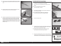
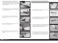
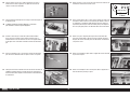
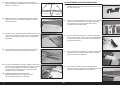
26. Use a #1 Phillips screwdriver to thread a #4 x 1/2 inch sheet metal
screw into each of the holes. Remove the screws before proceeding.
It is important to prepare and harden the surrounding wood
when mounting the control horns. Failure to do so may result
in the control horns not being as secure as necessary.
27. Place 2-3 drops of thin CA in each of the holes. Allow the CA to fully
cure before proceeding.
29. Attach a solder-type clevis to the center hole of the aileron control
horn.
30. Hold the pushrod against the clevis. Use a felt-tipped pen to mark
the edge of the clevis on the pushrod.
28. Mount the control horn to the aileron using four #4 x 1/2 inch sheet
metal screws. Tighten the screws using a #1 Phillips screwdriver.
31. Remove the pushrod from the servo. Use side cutters to trim the
pushrod 3/8 inch (9.5mm) past the mark made in the previous step.
This will be inserted into the solder clevis.
32. Use medium grit sandpaper to lightly scuff the pushrod. Use a paper
towel and isopropyl alcohol to remove any debris or oils from the
pushrod.
If the mark is removed, make sure to replace it on the pushrod.
33. Apply a small amount of fl ux paste to the pushrod. This will help
draw the solder along the pushrod wire and into the clevis.
34. Hold the pushrod and clevis using pliers or hemostats. Use a torch or
soldering iron to heat the clevis and wire. Use silver solder to secure
the clevis to the pushrod wire.
Align the clevis with the mark on the pushrod wire
to achieve the correct length of the pushrod.
Once the solder has cooled, pull hard on the pushrod wire
and clevis to make sure it has been soldered securely
in place. Failure to correctly solder the clevises can
result in pushrod failure and the loss of the model.
Use silver solder when assembling the pushrod.
8EN

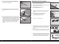
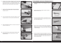
35. Remove the nut and clevis from the threaded end of the pushrod.
Slide a retainer on the pushrod wire and over the barrel of the solder
clevis.
36. Attach the solder clevis to the control horn. Slide the retainer over
the forks of the clevis to secure it to the control horn.
37. Thread the nut and threaded clevis back into place on the pushrod.
Attach the threaded clevis to the servo arm. Make sure to adjust
the clevis to center the aileron when the servo is centered. Apply
a drop of threadlock on the threads of the pushrod near the clevis.
Thread the nut over the threadlock and against the clevis. Use pliers
to tighten the nut against the clevis, then slide the retainer over the
forks of the clevis.
Operational flaps are optional on this model. They can
be added at any time during the life of the model.
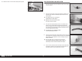
1. Use a razor saw to cut the two dowels connecting the fl ap and
aileron.
There is a gap between the flap and aileron
where these dowels are located.
2. Use medium grit sandpaper to sand the dowels smooth with the
face of the aileron and fl ap.
If the covering becomes damaged, use a covering iron
and white covering to replace any damaged covering.
4. Install the fl ap servos in the wing. The procedure is the same as the
aileron servos. When installing the fl ap servos, the servo arm on
both servos will face toward the left wingtip.
Installing the flap servos facing the same direction allows
their connection to the receiver using a Y-Harness.
5. Prepare the pushrod for the fl aps. This is the same procedure as the
pushrod for the aileron. When attaching the clevis to the servo arm,
use the hole that is 5/8 in (16mm) from the center of the servo horn.
3. Prepare the two fl ap servos.
FLAP SERVO INSTALLATION (OPTIONAL)
9 EN
Tiger 30cc ARF
5/8 inch
(16mm)

6. Install the control horn and complete the pushrod. These steps are
the same as the aileron control horn and pushrod steps.
7. Route the lead for the fl ap servo through the wing and out the hole
in the top of the wing.
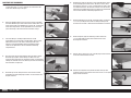
The wing must be installed before the stabilizer, as it is essential to
align the stabilizer with the wing for the aircraft to perform properly.
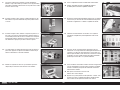
1. Test fi t the dowel into the leading edge of the wing. The dowel will
protrude 1/2 inch (13mm) from the wing. Remove the dowel and mix
a small amount of 5-minute epoxy. Use a toothpick to apply epoxy
inside the hole.
There are two larger diameter dowels, and one smaller
diameter dowel. The two larger diameter dowels are
used at the leading edge, and the smaller diameter
dowel at the trailing edge as an alignment pin.
2. Apply epoxy to the portion of the dowel that fi ts into the wing. Slide
the dowel into position, and remove any excess epoxy using a paper
towel and isopropyl alcohol.
The remaining wing dowel can be installed at this time.
3. Use a pencil to mark a centerline on the smaller diameter dowel.
4. Use epoxy to glue the dowel into the wing near the trailing edge.
Insert the dowel up to the line made in the previous step. Remove
any excess epoxy using a paper towel and isopropyl alcohol.
WING AND STABILIZER INSTALLATION
10EN

5. Slide the wing tube into the wing tube socket.
The wing tube may be a tight fit in the socket. Polishing
the wing tube with fine sand paper or steel wool will
help ease the installation of the wing tube.
6. Slide the wing panels together. There should be no gap between the
panels.
7. Slide the canopy hatch forward to release the tab at the rear near
the top of the fuselage. Lift the canopy hatch from the fuselage and
set it aside.
Pilot shown is optional and not included with the model.
8. Use a hobby knife and #11 blade to remove the covering from the
slot at the rear of the fuselage for the stabilizer.
9. Use a hobby knife and #11 blade to remove the covering at the rear
of the fuselage. Remove the tail post from the fuselage.
The tail post is left in position at the factory to prevent damage
and maintain the structural integrity of the fuselage during
shipping and must be removed to install the stabilizer.
10. Slide the wing into position, guiding the dowels in the wing into the
holes in the fuselage. Make sure the leads from the ailerons (and
fl aps) are inside the fuselage.
11. Secure the wing to the fuselage using the two 1/4-20 x 2 inch nylon
bolts. Use a fl at screwdriver to tighten the bolts, securing the wing.
12. Place the stabilizer in position. Make sure to slide the stabilizer
as far forward in the fuselage as possible. Use a hobby knife and
#11 blade to remove the covering between the slot for the fi n and
the opening for the tab on the fi n. Use care to only cut through the
covering as not to damage the underlying structure.
Use low heat on your covering iron to seal the edges of the
covering. High heat may result in the covering pulling back
and exposing bare balsa when the fin is glued in place.
13. Fit the fi n into position. The fi n will help in aligning the stabilizer to
the fuselage, as it keys into both items.
14. Stand back 8-10 feet (2-3 meters) and check that the stabilizer
is aligned with the wing. Lightly sand the stabilizer saddle on the
fuselage to correct any misalignment.
11 EN
Tiger 30cc ARF
AA
A=A

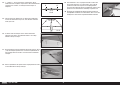
15. Measure from each wing tip to each stabilizer tip. Adjust the
stabilizer so the measurements are the same for both sides.
16. Place two T-pins into the stabilizer on both sides of the fuselage.
These will help return the stabilizer to the correct position in the
fuselage.
18. Use an epoxy brush to apply epoxy to the exposed wood in the
stabilizer slot of the fuselage.
19. Slide the stabilizer into position. Check the alignment to verify it
is correctly positioned. Use a paper towel and isopropyl alcohol to
remove any epoxy from the fuselage and stabilizer. Allow the epoxy
to fully cure before proceeding.
Regularly check the stab alignment while the epoxy is curing to
make sure it does not move and sets in a misaligned angle.
17. Remove the fi n and stabilizer from the fuselage. Mix 1 ounce (30ml)
of 30-minute epoxy and use an epoxy brush to apply it to the
exposed wood on the top and bottom of the stabilizer.
1. Prepare both elevator servos by installing the grommets and eyelets.
Do not install the screw that secures the servo arm to the servo.
2. Mount an elevator servo in the fuselage with the output facing the
front of the fuselage. The steps for mounting servos are the same as
in the section for the aileron servo installation.
3. Prepare the clevis by sliding a retainer on the barrel of the clevis.
Thread a 4-40 nut, then the clevis, on the threaded end of a long
pushrod. Attach the clevis to the elevator control horn.
4. Use a stiff ruler and two clamps to hold the elevator in position while
installing the elevator control horn and elevator pushrod.
5. Slide the pushrod into the pushrod tube in the fuselage. Make sure
to use the hole closest the stabilizer on the side where both the
rudder and elevator pushrods exit.
ELEVATOR SERVO INSTALLATION
12EN
AA
A=A

6. Position the control horn so the holes in the control horn align
with the hinge line. The pushrod will cause the control horn to fall
naturally on the elevator. Mark the location for the control horn
mounting screws on the elevator.
7. Move the control horn away from the elevator. Use a pin vise and
7/64-inch (2.5mm) drill bit to drill the holes for the control horn
mounting screws. Use care to drill the holes straight and parallel in
the elevator.
Unlike the aileron control horns, the elevator control
horns use a backplate on the opposite side of the
control surface. Failure to fit this backplate will result
in control failure and possible loss of the model.
9. The socket head cap screws will thread into the control horn back
plate. Use a 3/32-inch hex wrench to tighten all four screws.
Do not over-tighten the screws and damage the
underlying structure of the elevator.
10. When attaching the clevis to the servo arm, use the hole that is 5/8
in (16mm) from the center of the servo horn.
8. Use four 4-40 x 3/4 inch socket head cap screws to attach the
control horn to the elevator.
11. Attach a solder-type clevis to the elevator servo arm. Hold the
pushrod against the clevis. Use a felt-tipped pen to mark the edge of
the clevis on the pushrod.
12. Remove the pushrod from the fuselage. Remove the clevis from the
elevator servo arm. Cut the pushrod and solder the clevis on the
pushrod using the technique outlined for the aileron pushrods.
Once the solder has cooled, pull hard on the pushrod wire
and clevis to make sure it has been soldered securely
in place. Failure to correctly solder the clevises can
result in pushrod failure and the loss of the model.
14. Install the remaining control horn on the opposite elevator.
13. Reinstall the pushrod and connect it to the servo arm and control
horn. With the radio system on and elevator servo centered, adjust
the clevis to center the elevator. Use threadlock near the threaded
clevis, then tighten the nut against the clevis to secure the clevis.
Slide all retainers over the forks of the clevises to complete the
pushrod installation.
13 EN
Tiger 30cc ARF
5/8 inch
(16mm)

15. Complete the pushrod installation for the remaining elevator. Once
complete, make sure to install the screws that secure the servo
arms in the servos. Turn off the radio system.
1. Fit the fi n in position. Use a hobby square to make sure the fi n is
square to the stabilizer. If not, lightly sand the fi n where it fi ts into
the stabilizer and fuselage to correct the alignment.
3. Apply epoxy to the exposed wood inside the rear of the fuselage.
4. Apply epoxy to the exposed wood on the fi n where it will contact the
fuselage. Also apply epoxy under the fi n to glue it to the top of the
fuselage where the covering was removed.
2. Remove the fi n from the fuselage. Mix 1 ounce (30ml) of 30-minute
epoxy and use an epoxy brush to apply it to the exposed wood in the
stabilizer.
5. Fit the fi n into position and check the alignment. Use low-tack tape
to hold the fi n in position until the epoxy fully cures. Continually
check the fi n to make sure it remains aligned with the stabilizer as
the epoxy cures.
RUDDER AND FIN INSTALLATION
14EN

1. Prepare the rudder pushrod and install the rudder control horn
following the procedure outlined for the elevator control horn.
Unlike the aileron control horns, the rudder control
horn uses a backplate on the opposite side of the
control surface. Failure to fit this backplate will result
in control failure and possible loss of the model.
2. When attaching the clevis to the rudder servo horn, use the hole that
is 5/8 inch (16mm) from the center of the servo arm.
4. Install the rudder servo in the fuselage with the servo output facing
the rear of the aircraft. Align the rudder pushrod with the hole in the
arm the clevis will be attached. Mount the servo following the same
procedure as the aileron and elevator servos.
5. Prepare and secure the clevis for the rudder pushrod that completes
the rudder pushrod. The steps are outlined in the aileron servo
pushrod installation.
3. Center the rudder servo using the radio system. Install the servo arm
on the servo perpendicular to the servo centerline. Use side cutters
to remove any arms that may interfere with the operation of the
servo,
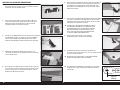
1. Mark the bottom of the rudder 1
1
/
2
and 2
1
/
2
inches (38mm and
63mm) back from the rudder hinge line.
2. Use a rotary tool and cut-off wheel to make a slot that is centered on
the bottom of the rudder between the two marks. Use a hobby knife
with a #11 blade to carefully trim the slot until the tail wheel bushing
fi ts into the slot, fl ush with the bottom of the rudder.
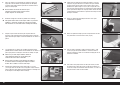
4. Guide the tiller arm from the tail wheel assembly through the
bushing. The bracket will rest fl at on the fuselage. If not, carefully
bend the tiller arm until the bracket rests fl at on the fuselage. The
vertical hole in the bracket will align with the rudder hinge line.
5. Center the bracket on the fuselage and use a felt-tipped pen to mark
the positions for the three mounting screws on the bottom of the
fuselage.
3. Mix a small amount of 5-minute epoxy and use it to glue the tail
wheel bushing in the rudder. Make sure to apply epoxy in the
slot and to the bushing. Remove any excess epoxy using a paper
towel and isopropyl alcohol. Allow the epoxy to fully cure before
proceeding.
RUDDER SERVO INSTALLATION TAIL WHEEL INSTALLATION
15 EN
Tiger 30cc ARF
5/8 inch
(16mm)

6. Remove the bracket. Use a drill and 5/64-inch (2mm) drill bit to
drill the holes for the mounting screws. Make sure to prepare the
holes by threading a #4 x 1/2 inch sheet metal screw into each hole.
Remove the screw and apply two to three drops on thin CA in each
hole. Allow the CA to fully cure before proceeding.
7. Attach the tail wheel bracket to the fuselage using three #4 washers
and three #4 x 1/2 inch sheet metal screws. Tighten the screws
using a #1 Phillips screwdriver.
8. Slide the wheel collar against the bracket. Use a .050” hex wrench
to tighten the setscrew in the wheel collar.
9. Use a fl at fi le to make a 1/4 inch wide fl at area on the tail gear wire.
1. Use a hobby knife and #11 blade to remove the covering from the
bottom of the fuselage for the landing gear mounting screws.
2. Use a rotary tool with a cut-off wheel to trim the axle to a length of
1
5
/
8
inches (41mm).
4. Attach the axle to the landing gear using the axle nut. Use 7/16 inch
and 1/2 inch wrench to tighten the nut, securing the axle. Make sure
the fl at areas face toward the bottom of the landing gear.
5. Slide a wheel collar on the axle. Place a drop of threadlock on a
6-32 x 3/4 inch socket head cap screw. Use the screw to secure the
wheel collar against the nut on the axle. Use a 7/64 inch hex wrench
to tighten the screw on the fl at areas on the axle.
3. Use a fl at fi le to make a 1/4 inch (6mm) wide fl at area at the end of
the axle. Make a second 1/4 inch (6mm) wide fl at area against the
nut on the axle.
10. Secure the tail wheel to the wire using a wheel collar. Tighten the
setscrew on the fl at area using a .050” hex wrench.
MAIN LANDING GEAR INSTALLATION
16EN

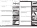
1. Install the receiver in the fuselage. Mount any remote receivers in
the fuselage using hook and loop tape.
Apply a small amount of 5-minute epoxy to the hook
and loop tape to secure it to the radio tray.
2. Secure the receiver battery in the fuselage. The battery location can
be changed to help in adjusting the Center of Gravity.
3. Remove the covering for the switch using a hobby knife with a
#11 blade. Use the opening that best fi ts the switch for your radio
system. Secure the switch in the side of the fuselage.
6. Apply a drop of light machine oil on the axle.
7. Slide the wheel on the axle. Secure the wheel using a wheel
collar and 6-32 x 1/4 inch socket head cap screw. Place a drop of
threadlock on the threads of the screw before tightening it using a
7/64 inch hex wrench.
8. Attach the landing gear to the fuselage using four 6-32 x 3/4 inch
socket head cap screws, four #6 washers and four #6 lock washers.
Apply a drop on the threads of each screw before threading them
through the landing gear and into the blind nuts. Tighten the screws
using a 7/64 inch hex wrench.
The landing gear will angle forward slightly when installed.
9. Attach the wheel pants to the landing gear using two 4-40 x 1/2 inch
machine screws and two #4 washers. Apply a drop of threadlock on
the threads of each screw before tightening them using a #1 Phillips
screwdriver.
RECEIVER AND RECEIVER BATTERY INSTALLATION
17 EN
Tiger 30cc ARF

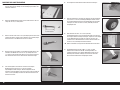
5. A second set of sides, as well as top and bottom pieces will fi t over
those previously installed.
Once the fit of the pieces has been checked, disassemble
the motor box and sort the pieces so they can be quickly
identified when assembling the motor box using epoxy.
STEP 1
We highly recommend using an epoxy with a cure time of at least
30 minutes or longer when assembling the motor box to allow
enough time to fully assemble it before the epoxy begins to cure.
6. Mix 1/2 ounces (15mL) of 30-minute epoxy. Use an epoxy brush to
apply epoxy to one side of the end plates.
7. Stack a second end plate on the fi rst, then apply epoxy to the plate.
Stack the third end plate. There will be epoxy between each of the
three end plates.
Assemble the motor box without mixing any epoxy first
to fully understand the fit of the components. Once epoxy
has been mixed, there will be a limited amount of time to
build the motor box before the epoxy begins to cure.
The motor box will be built in three steps. This
will allow time to assemble the motor box.
1. Locate the four end plates for the motor box. Three will be used for
the motor mounting, and one will be used when mounting the motor
box to the fi rewall.
2. Fit the three end plate in the wide slot in the motor box top/bottom.
The single end plate fi ts in the narrow slot.
The top/bottom has tabs along the sides.
3. Fit the motor box top/bottom on the end plates.
4. The motor box sides can then be fi t to the assembly.
The sides have notches that the tabs on the top/bottom will key into.
8. Apply epoxy to the area on the side plate where the end plates will
be in contact with the side plate. Position the end plates (previous
step and single plate) on the side plate. Continue working until the
motor box has the fi rst set of side plates and top/ bottom plates in
position.
9. Use low-tack tape to hold the motor box together until the epoxy
cures. Use a paper towel and isopropyl alcohol to remove any
excess epoxy.
It is critical to remove all excess epoxy or the
remaining pieces will not fit into position.
ELECTRIC MOTOR BOX ASSEMBLY
18EN

STEP 2
10. Mix 1/2 ounces (15mL) of 30-minute epoxy. Use an epoxy brush to
apply epoxy to one of the top/bottom plates. Apply epoxy to the top/
bottom plate.
11. Place a second top/bottom plate in position. Repeat until the second
set of side plates and top/bottom plates have been positioned.
STEP 3
13. Mix 1/2 ounces (15mL) of 30-minute epoxy. Apply epoxy to a single
square end plate.
14. Place the square end plate in position. Repeat for the fi nal square
end plate.
12. Use low-tack tape to hold the motor box together until the epoxy
cures. Use a paper towel and isopropyl alcohol to remove any
excess epoxy.
It is critical to remove all excess epoxy or the
remaining pieces will not fit into position.
15. Use low-tack tape to hold the motor box together until the epoxy
cures. Use a paper towel and isopropyl alcohol to remove any excess
epoxy. Allow the epoxy to fully cure before proceeding.
Use medium grit sandpaper to sand the motor
box if necessary for a finished took.
19 EN
Tiger 30cc ARF

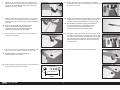
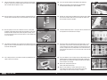
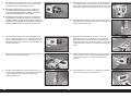
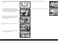
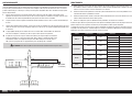
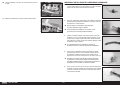
1. Measure and mark the locations for the motor box mounting screws
on the fi rewall.
These measurements are used when mounting the included
motor box to the firewall. Using a different motor or motor box
may require different measurements. Check the alignment of the
motor mor motor box after marking the firewall for alignment.
2. Use a drill and 7/32-inch (5.5mm) drill bit to drill the holes from the
previous step.
Drill a 1/8-inch (3mm) pilot hole first to prevent the larger
drill bit from wandering when drilling the final holes.
4. Attach the motor box to the fi rewall using the four 8-32 x 3/4 inch
socket head cap screws and four #8 washers. Tighten the screws
using a 9/64 inch hex wrench.
3. Use an 8-32 x 3/4 inch socket head cap screw and #8 washer to
pull the 8-32 blind nuts into the back of the fi rewall from inside the
fuselage. Use a 9/64 inch hex wrench for the screws. Remove the
screws once all blind nuts have been installed.
5. Attach the motor to the motor box using four 8-32 blind nuts, four #8
washers, four #8 lock washers and four 8-32 x 3/4 inch socket head
cap screws.
Use a 7/32-inch (5.5mm) drill bit to clear any epoxy from
the mounting holes. Drilling slightly larger mounting holes
will allow for any alignment when using different motors.
The Tiger 30cc has been designed to use a variety of power
systems. Please make sure to check the power system selected
has mounting holes that align with holes in the motor box. New
holes may be required dependant on the motor selection.
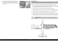
8. Remove the motor and motor box from the fi rewall. Mix 1/4 ounce
(8mL) of 5-minute epoxy. Slide the fi rewall so epoxy can be applied
in the fi nal locations for the fi rewall.
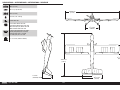
6. Position the fi rewall so the distance shown measures between
7
1
/
4
–7
3
/
4
inches (184mm–196mm). This measurement may vary
depending on motor selection. Verify the measurement is within this
range when the motor has been attached to the fi rewall.
7. Use a pencil to mark the location of the fi rewall on the fuselage
sides and top.
ELECTRIC MOTOR INSTALLATION
20EN
1 inch
(25mm)
1 inch
(25mm)
1 inch
(25mm)
1 inch
(25mm)
La pagina si sta caricando...
La pagina si sta caricando...
La pagina si sta caricando...
La pagina si sta caricando...
La pagina si sta caricando...
La pagina si sta caricando...
La pagina si sta caricando...
La pagina si sta caricando...
La pagina si sta caricando...
La pagina si sta caricando...
La pagina si sta caricando...
La pagina si sta caricando...
La pagina si sta caricando...
La pagina si sta caricando...
La pagina si sta caricando...
La pagina si sta caricando...
La pagina si sta caricando...
La pagina si sta caricando...
La pagina si sta caricando...
La pagina si sta caricando...
La pagina si sta caricando...
La pagina si sta caricando...
La pagina si sta caricando...
La pagina si sta caricando...
La pagina si sta caricando...
La pagina si sta caricando...
La pagina si sta caricando...
La pagina si sta caricando...
La pagina si sta caricando...
La pagina si sta caricando...
La pagina si sta caricando...
La pagina si sta caricando...
La pagina si sta caricando...
La pagina si sta caricando...
La pagina si sta caricando...
La pagina si sta caricando...
La pagina si sta caricando...
La pagina si sta caricando...
La pagina si sta caricando...
La pagina si sta caricando...
La pagina si sta caricando...
La pagina si sta caricando...
La pagina si sta caricando...
La pagina si sta caricando...
La pagina si sta caricando...
La pagina si sta caricando...
La pagina si sta caricando...
La pagina si sta caricando...
La pagina si sta caricando...
La pagina si sta caricando...
La pagina si sta caricando...
La pagina si sta caricando...
La pagina si sta caricando...
La pagina si sta caricando...
La pagina si sta caricando...
La pagina si sta caricando...
La pagina si sta caricando...
La pagina si sta caricando...
La pagina si sta caricando...
La pagina si sta caricando...
La pagina si sta caricando...
La pagina si sta caricando...
La pagina si sta caricando...
La pagina si sta caricando...
La pagina si sta caricando...
La pagina si sta caricando...
La pagina si sta caricando...
La pagina si sta caricando...
La pagina si sta caricando...
La pagina si sta caricando...
La pagina si sta caricando...
La pagina si sta caricando...
La pagina si sta caricando...
La pagina si sta caricando...
La pagina si sta caricando...
La pagina si sta caricando...
La pagina si sta caricando...
La pagina si sta caricando...
La pagina si sta caricando...
La pagina si sta caricando...
La pagina si sta caricando...
La pagina si sta caricando...
La pagina si sta caricando...
La pagina si sta caricando...
La pagina si sta caricando...
La pagina si sta caricando...
La pagina si sta caricando...
La pagina si sta caricando...
La pagina si sta caricando...
La pagina si sta caricando...
La pagina si sta caricando...
La pagina si sta caricando...
La pagina si sta caricando...
La pagina si sta caricando...
La pagina si sta caricando...
La pagina si sta caricando...
La pagina si sta caricando...
La pagina si sta caricando...
La pagina si sta caricando...
La pagina si sta caricando...
-
 1
1
-
 2
2
-
 3
3
-
 4
4
-
 5
5
-
 6
6
-
 7
7
-
 8
8
-
 9
9
-
 10
10
-
 11
11
-
 12
12
-
 13
13
-
 14
14
-
 15
15
-
 16
16
-
 17
17
-
 18
18
-
 19
19
-
 20
20
-
 21
21
-
 22
22
-
 23
23
-
 24
24
-
 25
25
-
 26
26
-
 27
27
-
 28
28
-
 29
29
-
 30
30
-
 31
31
-
 32
32
-
 33
33
-
 34
34
-
 35
35
-
 36
36
-
 37
37
-
 38
38
-
 39
39
-
 40
40
-
 41
41
-
 42
42
-
 43
43
-
 44
44
-
 45
45
-
 46
46
-
 47
47
-
 48
48
-
 49
49
-
 50
50
-
 51
51
-
 52
52
-
 53
53
-
 54
54
-
 55
55
-
 56
56
-
 57
57
-
 58
58
-
 59
59
-
 60
60
-
 61
61
-
 62
62
-
 63
63
-
 64
64
-
 65
65
-
 66
66
-
 67
67
-
 68
68
-
 69
69
-
 70
70
-
 71
71
-
 72
72
-
 73
73
-
 74
74
-
 75
75
-
 76
76
-
 77
77
-
 78
78
-
 79
79
-
 80
80
-
 81
81
-
 82
82
-
 83
83
-
 84
84
-
 85
85
-
 86
86
-
 87
87
-
 88
88
-
 89
89
-
 90
90
-
 91
91
-
 92
92
-
 93
93
-
 94
94
-
 95
95
-
 96
96
-
 97
97
-
 98
98
-
 99
99
-
 100
100
-
 101
101
-
 102
102
-
 103
103
-
 104
104
-
 105
105
-
 106
106
-
 107
107
-
 108
108
-
 109
109
-
 110
110
-
 111
111
-
 112
112
-
 113
113
-
 114
114
-
 115
115
-
 116
116
-
 117
117
-
 118
118
-
 119
119
-
 120
120


Hangar 9 HAN2370 Manuale del proprietario
- Categoria
- Giocattoli telecomandati
- Tipo
- Manuale del proprietario
in altre lingue
- English: Hangar 9 HAN2370 Owner's manual
- français: Hangar 9 HAN2370 Le manuel du propriétaire
- Deutsch: Hangar 9 HAN2370 Bedienungsanleitung
Documenti correlati
-
 Hangar 9 HANGAR 9 Ultra Stick 30cc Manuale del proprietario
-
 Hangar 9 HAN4885 Manuale del proprietario
-
Evolution 33cc Manuale del proprietario
-
 Hangar 9 HAN2345 Manuale del proprietario
-
 Hangar 9 HAN2890 Manuale del proprietario
-
 Hangar 9 HAN2530 Manuale del proprietario
-
 Hangar 9 HAN2820 Manuale del proprietario
-
 Hangar 9 HAN5065 Manuale del proprietario
-
 Hangar 9 HAN2990 Manuale del proprietario
-
 Hangar 9 HAN3185 Manuale del proprietario


Altri documenti
-
E-flite Habu 32x DF Manuale utente
-
arf EFL2790 Manuale del proprietario
-
Spektrum SPMSA6380 Manuale del proprietario
-
 Ion Science Tiger handheld VOC detector Manuale utente
-
Rothenberger Power threader SUPERTRONIC 1250 Manuale utente
-
Kreg KPHJ230 Manuale del proprietario
-
Westfalia 961197 Self Centering Dowelling Jig Manuale utente
