
TRADEMARK
All products and company names are trademarks or
registered trademarks of their respective holders.
These specifications are subject to change without notice.
Manual Revision 1.0
August 9, 1999
EP-MVP4FEP-MVP4F
EP-MVP4FEP-MVP4F
EP-MVP4F
ISAISA
ISAISA
ISA
/PCI Mainboard with Onboard AGP/PCI Mainboard with Onboard AGP
/PCI Mainboard with Onboard AGP/PCI Mainboard with Onboard AGP
/PCI Mainboard with Onboard AGP
VGA, PCI Audio, PCI IDE and SuperVGA, PCI Audio, PCI IDE and Super
VGA, PCI Audio, PCI IDE and SuperVGA, PCI Audio, PCI IDE and Super
VGA, PCI Audio, PCI IDE and Super
Multi-I/OMulti-I/O
Multi-I/OMulti-I/O
Multi-I/O

EP-MVP4F
User Notice
No part of this product, including the product and software may be reproduced,
transmitted, transcribed, stored in a retrieval system, or translated into any
language in any form without the express written permission of EPoX Computer
Company (hereinafter referred to as EPoX) except for documentation kept by the
purchaser for backup purposes.
We provide this manual “as is” without warranty of any kind, either expressed or
implied, including but not limited to the implied warranties or conditions of
merchantability or fitness for a particular purpose. In no event shall EPoX be
liable for any loss of profits, loss of business, loss of use or data, interruption of
business or for indirect, special incidental, or consequential damages of any kind,
even if EPoX has been advised of the possibility of such damages arising from any
defect or error in the manual or product. EPoX may revise this manual from time
to time without notice. For updated BIOS, drivers, or product release information
you may visit our websites at http://www.epox.com or http://www.epox.com.tw.
Products mentioned in this manual are mentioned for identification purposes only.
Product names appearing in this manual may or may not be registered trademarks
or copyrights of their respective companies. The product name and revision
number are both printed on the mainboard itself.
Handling Procedures
Static electricity can severely damage your equipment. Handle the EP-MVP4F and
any other device in your system with extreme care and avoid unnecessary contact
with system components on the mainboard. Always work on an antistatic surface
to avoid possible damage to the mainboard from static discharge. Always have the
power supply unplugged and powered off when inserting and removing devices
within the computer chassis. EPoX assumes no responsibility for any damage to
the EP-MVP4F mainboard that results from failure to follow instruction or failure
to observe safety precautions.
CAUTION
The EP-MVP4F mainboard is subject to
damage by static electricity. Always
observe the handling procedures.

EP-MVP4F
Technical Support Services
If you need additional information, help during installation or normal use of this
product, please contact your retailer. Your retailer will have the most current
information about your configuration. If your retailer cannot help, you may visit
our online technical support website and/or contact our support technicians at the
locations listed below.
Record your serial number before installing your EP-MVP4F mainboard. (The
serial number is located near the PCI slots at the edge of the board.)
EP-MVP4F serial number: _________________________________
Contacting Technical Support
EPoX technical support is working hard to answer all of your questions online.
From our website you can find answers to many common questions, drivers, BIOS
updates, tech notes, and important technical bulletins. If you are still unable to
locate the solution you are seeking, you always have the option to contact our
support technicians directly.
North American website (English language)
http://www.epox.com
European website (Multi-language)
http://www.epox.nl
Taiwan website (Chinese language)
http://www.epox.com.tw
Thank you for using EPoX mainboards!
Copyright 1999 EPoX Computer Company. All rights reserved.

EP-MVP4F
Table of Contents
Section 1 Introduction
Components Checklist ............................................... 1-1
Overview
EP-MVP4F Form-factor ............................................ 1-2
I/O Shield Connector ................................................. 1-3
Power-On/Off (Remote)............................................ 1-3
System Block Diagram...............................................1-4
Section 2 Features
EP-MVP4F Features ..................................................2-1
Section 3 Installation
EP-MVP4F Detailed Layout ...................................... 3-1
Easy Installation Procedure
Configure DIP Switch ................................................ 3-3
System Memory Configuration ................................. 3-5
Device Connectors ..................................................... 3-7
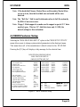
Section 4 Award BIOS Setup
BIOS Instructions ....................................................... 4-1
Standard CMOS Setup ................................................4-2
BIOS Features Setup .................................................. 4-3
Chipset Features Setup...............................................4-8
Power Management Setup.......................................... 4-11
PNP/PCI Configuration ............................................. 4-14
Load Setup Defaults ................................................... 4-16
Integrated Peripherals ................................................ 4-16
Sensor and CPU Speed Setup..................................... 4-21
Change Supervisor or User Password .......................4-23
IDE HDD Auto Detection .......................................... 4-24

EP-MVP4F
Save & Exit Setup ....................................................... 4-26
Exit Without Saving .................................................... 4-26
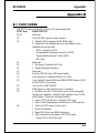
Section 5 Appendix
Appendix A
Memory Map ..............................................................A-1
I/O Map ....................................................................... A-1
Timer & DMA Channels Map .................................... A-2
Interrupt Map .............................................................. A-2
RTC & CMOS RAM Map ........................................... A-3
Appendix B
POST Codes................................................................ A-5
Unexpected Errors ..................................................... A-8
Appendix C
Load Setup Defaults ................................................... A-9
Appendix D
GHOST 5.1 Quick User’s Guide................................A-11

EP-MVP4F
Page Left Blank

IntroductionEP-MVP4F
Page 1-1
Section 1
INTRODUCTION
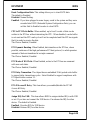
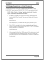
Components Checklist
üü
üü
ü A. (1) One mainboard
üü
üü
ü B. (1) One user’s manual
üü
üü
ü C. (1) Floppy ribbon cable
üü
üü
ü D. (1) ATA-66 IDE ribbon cable
üü
üü
ü E. (1) COM Port Connector
üü
üü
ü F. (1) Driver and utility
USER’S
MANUAL
EP-MVP4F
B
A
C
D
F
or
E

Introduction EP-MVP4F
Page 1-2
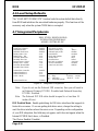
EP-MVP4F Form Factor
The EP-MVP4F is designed with MicroATX form factor - the new industry
standard of chassis. The MicroATX form factor is essentially a Baby-AT base-
board rotated 90 degrees within the chassis enclosure and a new mounting
configuration for the power supply. With these changes the processor is relocated
away from the expansion slots, allowing them all to hold full length add-in cards.
MicroATX defines a double height aperture to the rear of the chassis which can be
used to host a wide range of onboard I/O. Only the size and position of this
aperture is defined, allowing PC manufacturers to add new I/O features (e.g.; TV
input, TV output, joystick, modem, LAN, etc.) to systems. This will help systems
integrators differentiate their products in the marketplace, and better meet your
needs.
• Smaller size promotes a smaller system size.
• I/O shield does not need to be retooled in an ATX 2.01 or later. Mainboard
could be used in an ATX 2.01-compliant.
• A smaller power supply cam be used. High integration on mainboard reduces
the system costs.
Full length
slots
Expandable I/O
5 1/4"
Bay
3 1/2"
Bay
Figure 2: Summary of Micro ATX chassis features
CPU located near
Power Supply
Single chassis
fan for
system
Micro
ATX
Power
Supply
ATX power
connector
Floppy / IDE
connectors
close to
peripheral
bays

IntroductionEP-MVP4F
Page 1-3
Case (chassis) Power
ON/OFF button
ATX
POWER SUPPLY
Figure 4: Simple ATX Power
ON/OFF Controller
Power-On/Off (Remote)
The EP-MVP4F has a single 20-pin connector for ATX power supplies. For ATX
power supplies that support the Remote On/Off feature, this should be connected
to the systems front panel for system Power On/Off button. The systems power
On/Off button should be a momentary button that is normally open.
The EP-MVP4F has been designed with “Soft Off" functions. You can turn Off
the system from one of two sources: The first is the front panel Power On/Off
button, and the other is the "Soft Off" function (coming from the EP-MVP4F’s
onboard circuit controller) that can be controlled by the operating system.
Windows 95/98 will control this when the user clicks that they are ready to
Shutdown the system.
I/O Shield Connector
The EP-MVP4F is equipped with an I/O back panel.Please use the appropriate I/O
shield (figure 3).
J3
PS/2 Mouse
PS/2
KEYBOARD
COM1 VGA1
parallel port
Speaker
Joystick/Midi
USB port
Line_in
MIC
Figure 3

Introduction EP-MVP4F
Page 1-4
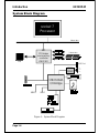
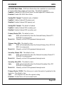
Figure 5: System Block Diagram
System Block Diagram
PAC
PCI Bridge
and memory
controller
VT82C501
socket 7
Processor
100/66 MHz
100/66 MHz
CRT
VT82C686A
I/O Bridge
USB 0 USB 1
AC97
CODEC
~
~
~
AMR Slot

FeaturesEP-MVP4F
Page 2-1
Section 2
FEATURES
EP-MVP4F Features:
• Intel Pentium
®
Processor, Pentium Processor with MMX technology,
AMD K6/K6-2/K6 III, Cyrix 6x86MX/MII, IDT C6/Winchip, and Rise mp6
series operating at 133 ~ 500MHz with 321 ZIF socket 7 provides
scalability to accept faster Processors in the future.
• Designed with VIA MVP4 AGPset.
• Supports up to 256 MB of DRAM (minimum of 8 MB) on board,
You can use 168-pin DIMM x 2. (please see Section 3-2).
• Supports (2) 32 bit PCI slots, (1) AMR Slot and provides (2) independent
high performance PCI IDE interfaces capable of supporting PIO Mode 3/4
and Ultra DMA 33/66 devices. The EP-MVP4F supports (2) PCI Bus Master
slots and a jumperless PCI INT# control scheme which reduces configura-
tion confusion when plugging in PCI card(s).
• Supports ATAPI (e.g. CD-ROM) devices on both Primary and Secondary
IDE interfaces.
• Designed with lntegrated Multi I/O: (1) floppy port, (1) parallel port
(EPP, ECP), and (2) serial ports (16550 Fast UART).
Note: Japanese “Floppy 3 mode” is also supported
• Features Award Plug & Play BIOS. With Flash Memory you can always
upgrade to the current BIOS as they are released. (http://www.epox.com
please visit our Technical Support section for the latest updates)
• EP-MVP4F utilizes a Lithium battery which provides environmental
protection and longer battery life.
• Software power-down when using Windows
®
95/98.

Features EP-MVP4F
Page 2-2
• Supports ring-in feature (remote power-on through external modem,
allows system to be turned on remotely).
• Resume by Alarm - Allows your system to turn on at a preselected time.
• Supports CPU Hardware sleep and SMM (System Management Mode).
• Supports USDM software to offer motherboard various status.
• Built-in WOL (Wake On Lan) Connector.
• Built-in Sound Blaster Compatible/DirectSound AC97 Audio.
• Built-in AGP 2D/3D Graphics Accelerator.

InstallationEP-MVP4F
Page 3-1
Section 3
INSTALLATION

Installation EP-MVP4F
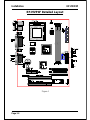
Page 3-2
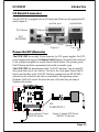
Figure 1
EP-MVP4F Detailed Layout

InstallationEP-MVP4F
Page 3-3
Easy Installation Procedure
The following must be completed before powering on your new system:
3-1. Configure Jumpers
3-2. System Memory Configuration
3-3. Device Connectors
Section 3-1
Configure Jumpers
We design this motherboard with the fastest jumpers to make your install fast and
easy.
Note: The jumpers as depicted as shown (Figure 1) in their correct physical orientation.
1WS
suB
kcolC
1234
NOzHM66
NOzHM57
NONOzHM38
NONOzHM09
NONOzHM59
NONONOzHM001
NONONOzHM501
NONONOzHM511
1WS
UPC
reilpitluM
6CTDI/xiryC/DMA
UPC
reilpitluM
2pihCniWTDI
567
NOX2
NONOX5.2
NOX3
X5.3
NONOX4
NONONOX5.4
NONOX533.2
NOX5.566.2
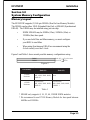
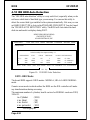
JP2: CPU Vcore Voltage Selection
SW1: CPU Speed Selection
2PJerocVUPC
7-1V0.2
8-2V2.2
9-3V4.2
01-4V8.2
11-5V9.2
21-6V2.3
SW1
17
2.0V
2.2V
2.4V
2.8V
2.9V
3.2V
JP2

Installation EP-MVP4F
Page 3-4
* Reserved
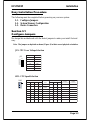
CPU Type SW1
CPU
Bus
Clock
CPU
Multiplier
Pentium/MMX
AMD K6/K6-2/K6III
IDT-C6
Cyrix /IBM
6x86MX/MII
IDT Winchip 2 Rise MP6
1234567
166MHz PR200 ON ON ON 66MHz
2.5X
PR233 ON ON ON 75MHz
PR266 233MHz ON ON ON ON 83MHz
PR300 *PR333 ON ON ON ON 95MHz
250MHz PR366 300MHz *PR366 ON ON ON ON ON 100MHz
200MHz PR266 200MHz ON ON 66MHz
3X
PR300 225MHz ON ON 75MHz
250MHz PR333 266Mhz ON ON ON 83MHz
PR400 *PR380 ON ON ON 95MHz
300MHz *PR433 *PR400 ON ON ON ON 100MHz
233MHz PR300 233MHz ON 66MHz
3.5X
PR333 ON 75MHz
*PR400 ON ON 83MHz
333MHz *PR466 *PR433 ON ON 95MHz
350MHz *PR500 *PR466 ON ON ON 100MHz
266MHz *PR333 266MHz ON ON ON 66MHz
4X
*PR400 ON ON ON 75MHz
333MHz *PR466 ON ON ON ON 83MHz
380MHz *PR533 ON ON ON ON 95MHz
400MHz *PR550 ON ON ON ON ON 100MHz
300MHz ON ON ON ON 66MHz
4.5X
450MHz ON ON ON ON ON ON 100MHz
333MHz ON ON ON 66MHz
5X475MHz ON ON ON ON 95MHz
*500MHz 266MHz ON ON ON ON ON 100MHz
366MHz ON ON 66MHz
5.5X
*550MHz 300MHz ON ON ON ON 100MHz
J7
WOL (Wakup On Lan) Connector
Reserved for NIC (Network Interface Card) to
Wake the System.

InstallationEP-MVP4F
Page 3-5
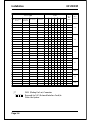
Section 3-2
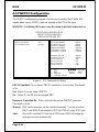
System Memory Configuration
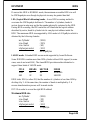
Memory Layout
The EP-MVP4F supports (2) 168-pin DIMMs (Dual In-line Memory Module).
The DIMMs can be either EDO (Extended Data Out) or SDRAM (Synchronized
DRAM). The DIMMs may be installed using just one chip.
• DIMM SDRAM may be 83MHz (12ns), 100MHz (10ns) or
125MHz (8ns) bus speed.
• If you use both 50ns and 60ns memory you must configure
your BIOS to read 60ns.
• When using Synchronous DRAM we recommend using the
4 clock variety over the 2 clock.
Figure 2 and Table 1 show several possible memory configurations using
yromeMlatoT
1MMID
)1/0knaB(
2MMID
)3/2knaB(
BM821=
mumixaM
*MARDS/ODE
,BM46,BM23,BM61,BM8
1XBM821
enoN
BM652=
mumixaM
*MARDS/ODE
,BM46,BM23,BM61,BM8
1XBM821
*MARDS/ODE
,BM46,BM23,BM61,BM8
1XBM821
DIMM 1
DIMM 2
Bank 0/1
Bank 2/3
-Synchronous
-EDO
Figure 2
* SDRAM only supports 8, 16, 32, 64, 128MB DIMM modules.
* We recommend to use PC100 Memory Module for bus speed between
66MHz and 100MHz.
Table 1

Installation EP-MVP4F
Page 3-6
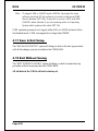
DIMM Module Installation
Figure 3 displays the notch marks and what they should look like on your DIMM
memory module.
DIMMs have 168-pins and two notches that will match with the onboard DIMM
socket. DIMM modules are installed by placing the chip firmly into the socket at
a 90 degree angle and pressing straight down (figure 4) until it fits tightly into the
DIMM socket (figure 5).
Figure 3
Figure 5
DIMM Module clip after installation
To remove the DIMM module simply press down both of the white clips on
either side and the module will be released from the socket.
Figure 4
DIMM Module clip before installation
CENTER KEY ZONE
(3.3 V DRAM)
LEFT KEY ZONE
(UNBUFFERED)

InstallationEP-MVP4F
Page 3-7
Section 3-3
Device Connectors
Please install the motherboard into the chassis.
PS/2 Mouse
PS/2
KEYBOARD
COM1 VGA1
parallel port
Speaker
Joystick/Midi
USB port
Line_in
MIC
Figure 6
J2: Chassis Panel Connector
• Power LED, Speaker, Reset
J3: Power_ON/OFF, Turbo LED, HDD LED, IR Connector
J4: CPU Fan Power
• A plug-in for the CPU Fan Power
J6: Chassis Fan Power
• A plug-in for the chassis Fan Power
J7: WOL (Wake On Lan) Connector
IDE1: Primary IDE Connector
IDE2: Secondary IDE Connector
FDD1: Floppy Controller Connector
PW1: ATX Power Connector
• 20-pin power connector
CD1: CD-ROM Audio_in Connector
MODEM1: Telephony Connector
• Pin1(Audio_in), Pin2/Pin3(GND), Pin4(Mic-out to Modem)

Installation EP-MVP4F
Page 3-8
Device Connectors (continued)
J2
Speaker - Connect to the system's speaker for beeping
1. Speaker 3. GND
2. N/C 4. GND
Reset - Closed to restart system.
Power LED - Power LED connector
1. Power LED(+) 4. NC
2. N/C 5. GND
3. GND
1
1
1
(This is connected to the power button on the case. Using the
Soft-Off by Pwr-BTTN feature, you can choose either Instant
Off (turns system off immediatly), or 4 sec delay (you need to
hold the button down for 4 seconds before the system turns off).
When the system is in 4 sec delay mode, there is a special feature
to make the system to go into suspend mode when the button is
pressed momentarily.)
Turbo LED indicator - LED ON when higher speed is selected
IDE LED indicator - LED ON when Onboard PCI IDE Hard
disks is activate
J3
1
+
+
IR Connector
1. VCC 4. GND
2. NC 5. IRTX
3. IRRX
1
Power On/Off
La pagina sta caricando ...
La pagina sta caricando ...
La pagina sta caricando ...
La pagina sta caricando ...
La pagina sta caricando ...
La pagina sta caricando ...
La pagina sta caricando ...
La pagina sta caricando ...
La pagina sta caricando ...
La pagina sta caricando ...
La pagina sta caricando ...
La pagina sta caricando ...
La pagina sta caricando ...
La pagina sta caricando ...
La pagina sta caricando ...
La pagina sta caricando ...
La pagina sta caricando ...
La pagina sta caricando ...
La pagina sta caricando ...
La pagina sta caricando ...
La pagina sta caricando ...
La pagina sta caricando ...
La pagina sta caricando ...
La pagina sta caricando ...
La pagina sta caricando ...
La pagina sta caricando ...
La pagina sta caricando ...
La pagina sta caricando ...
La pagina sta caricando ...
La pagina sta caricando ...
La pagina sta caricando ...
La pagina sta caricando ...
La pagina sta caricando ...
La pagina sta caricando ...
La pagina sta caricando ...
La pagina sta caricando ...
La pagina sta caricando ...
La pagina sta caricando ...
La pagina sta caricando ...
La pagina sta caricando ...
La pagina sta caricando ...
La pagina sta caricando ...
La pagina sta caricando ...
La pagina sta caricando ...
La pagina sta caricando ...
-
 1
1
-
 2
2
-
 3
3
-
 4
4
-
 5
5
-
 6
6
-
 7
7
-
 8
8
-
 9
9
-
 10
10
-
 11
11
-
 12
12
-
 13
13
-
 14
14
-
 15
15
-
 16
16
-
 17
17
-
 18
18
-
 19
19
-
 20
20
-
 21
21
-
 22
22
-
 23
23
-
 24
24
-
 25
25
-
 26
26
-
 27
27
-
 28
28
-
 29
29
-
 30
30
-
 31
31
-
 32
32
-
 33
33
-
 34
34
-
 35
35
-
 36
36
-
 37
37
-
 38
38
-
 39
39
-
 40
40
-
 41
41
-
 42
42
-
 43
43
-
 44
44
-
 45
45
-
 46
46
-
 47
47
-
 48
48
-
 49
49
-
 50
50
-
 51
51
-
 52
52
-
 53
53
-
 54
54
-
 55
55
-
 56
56
-
 57
57
-
 58
58
-
 59
59
-
 60
60
-
 61
61
-
 62
62
-
 63
63
-
 64
64
-
 65
65


EPOX EP-MVP4F Manuale utente
- Categoria
- Schede madri
- Tipo
- Manuale utente
in altre lingue
- English: EPOX EP-MVP4F User manual
Documenti correlati
Altri documenti
-
SOYO Super 7 SY-5EMA Manuale utente
-
 NiceHome PR300 Manuale del proprietario
-
Tyan TITAN TURBO ATX-2 Manuale utente
-
Kawai AnyTime ATX3L Manuale del proprietario
-
Peavey PRO Upgrade Kit Manuale del proprietario
-
3M Single Touch Displays Guida utente
-
Chamberlain LiftMaster PR433-4 Manuale del proprietario
-
Bticino M8TA Istruzioni per l'uso
