
User’s Manual
SR-Series
MOTION ANALYSIS SYSTEMS DIVISION
EASTMAN KODAK COMPANY

Table of Contents
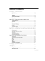
CHAPTER 1 - INTRODUCTION
Introduction ......................................................................................... 1.1
Table of contents ................................................................................. 1.2
Warranty .............................................................................................. 1.3
How to use this manual........................................................................ 1.4
Precautions .......................................................................................... 1.5
CHAPTER 2 - CONTROLS AND CONNECTORS
Visual introduction .............................................................................. 2.1
Processor.............................................................................................. 2.2
Processor rear panel............................................................................. 2.3
Processor front panel .......................................................................... 2.5
Camera................................................................................................. 2.6
Viewfinder display .............................................................................. 2.7
CHAPTER 3 - OPERATING THE MOTION CORDER SR SERIES
Getting started...................................................................................... 3.1
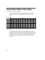
Preparing to make a recording............................................................. 3.2
Recording ............................................................................................ 3.8
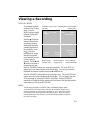
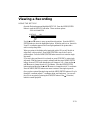
Viewing a recording ............................................................................ 3.9
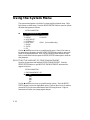
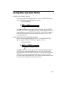
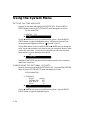
Using the system menu ........................................................................ 3.12
CHAPTER 4 - RECORDING STRATEGIES
Introduction ......................................................................................... 4.1
How the Processor stores images ........................................................ 4.2
Start...................................................................................................... 4.3
Center .................................................................................................. 4.4
End....................................................................................................... 4.5
Random................................................................................................ 4.6
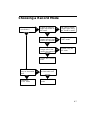
Choosing a record mode ...................................................................... 4.7
CHAPTER 5 - ROUTINE CARE
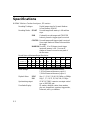
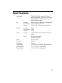
Specifications....................................................................................... 5.1
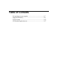
ADDENDUM
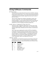
Using software command .................................................................... A.1
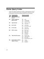
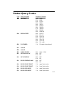
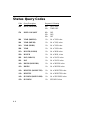
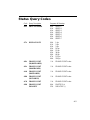
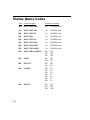
Status query codes ............................................................................... A.2
(continued)

Table of Contents
Moving Images to your computer........................................................ A.7
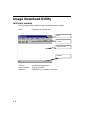
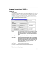
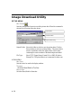
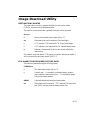
Image download utility ........................................................................ A.8
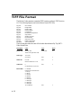
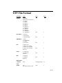
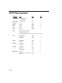
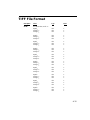
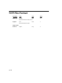
TIFF file format ................................................................................... A.12
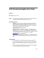
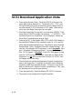
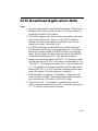
SCSI download application note.......................................................... A.17

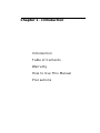
Chapter 1 - Introduction
Introduction
Table of Contents
Warranty
How to Use This Manual
Precautions

1.1
Introduction
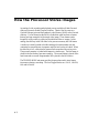
The KODAK Motion Corder Analyzer, SR series is designed to be a valuable
addition to the engineer’s problem solving tool kit. The compactness, ease of
operation, fast framing rates and instant video playback make evaluating your
most difficult motion related problems simple.
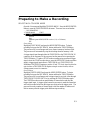
The live setup feature allows the user to see the image before recording so that
the time required to solve the problem is minimized. There is no guesswork
about exposure levels or image composition. What the user sees on the video
monitor is what will be captured in memory when the Trigger key is pressed.
The information in this manual will teach you how to operate the KODAK
Motion Corder Analyzer, SR series.

1.2
Warranty
NEW EQUIPMENT WARRANTY
KODAK MOTION CORDER ANALYZER, SR SERIES
Eastman Kodak Company, Motion Analysis Systems Division, warrants this KODAK
Motion Corder Analyzer, Model SR series and accessories manufactured by Eastman
Kodak Company, to function properly for one year from date of shipment, if the war-
ranty registration card was filled out and returned to KODAK San Diego within thirty
days of shipment.
Kodak agrees to perform the following equipment warranty services in the United States.
1. Repair service: If shipped to us, repairs will be made at no charge.
2. Parts replacement: Replacements parts installed under warranty will be provided
at no charge.
THIS WARRANTY DOES NOT APPLY UNDER THE FOLLOWING CONDITIONS:
Failure to operate the KODAK Motion Corder Analyzer, Model SR series in accordance
with Kodak’s written instructions, including environmental specifications listed in the
User’s Manual.
If there is evidence of the KODAK Motion Corder Analyzer, Model SR series being
subjected to accidental damage, misuse or abuse.
If the KODAK Motion Corder Analyzer, Model SR series has been repaired or tampered
with by persons other than Kodak personnel, customer personnel trained by Kodak or
without permission of Kodak.
Shipping damage is not covered by this warranty. The purchaser has the responsibility to
place a claim of damage in shipment with the carrier.
KODAK makes no other warranties, express or implied, including the implied warranties
of merchantability and fitness for a particular purpose. If this KODAK Motion Corder
Analyzer, Model SR series does not function properly during the warranty period,
KODAK will repair it without charge according to the terms stated above. Repair
without charge is KODAK’S only obligation under this warranty. KODAK will not be
responsible for any consequential or incidental damages resulting from the sale use or
improper functioning of this equipment even if loss or damage is caused by the negli-
gence or other fault of KODAK.
Manual Part Number 91000088-002 Rev. A
KODAK is a trademark.
© Copyright Eastman Kodak Company, 1998

1.3
How to Use This Manual
DEFINITION OF TERMS
You will notice as you read this manual that some of the information is pre-
sented as a NOTE, CAUTION or WARNING. It is important that you under-
stand the significance of these three terms.
NOTE
A note contains information that we wish to emphasize regarding the operation of
your Motion Corder SR series.
CAUTION
A caution is intended to warn you that a certain operation or condition may cause
harm to your Motion Corder SR series.
WARNING
A warning is important to the safety of everyone operating the Motion Corder SR
series and should not be disregarded under any circumstances.
CHAPTER ONE, INTRODUCTION
Contains the Warranty, precautions, introduction and how to use this manual.
CHAPTER TWO, CONTROLS AND CONNECTORS
An introduction to the components of your Motion Corder SR series. Explains
the use of each connector and control on the Camera and the Processor.
CHAPTER THREE, OPERATING THE MOTION CORDER SR SERIES
Explains how to make and playback a recording.
CHAPTER FOUR, RECORDING STRATEGIES
Provides a model for understanding how a solid state recorder works and also
provides the background information for selecting an appropriate record mode.
CHAPTER FIVE, SPECIFICATIONS
Contains specifications.
If you require additional information not included in this manual regarding the
care, technical service and operation of your Motion Corder SR series please
contact our service department in San Diego by calling:
800 - 854 - 7006

1.4
Precautions
TEMPERATURE
The KODAK Motion Corder Analyzer, SR series, is designed to operate satisfac-
torily in an environment where the ambient temperature is between -15 and 35
degrees Centigrade (5 and 95 degrees Fahrenheit), and there is no condensation
present.
STORAGE
Do not store the equipment in an area where the temperature will drop below -20
degrees or exceed 70 degrees Centigrade (-4 to 158 degrees Fahrenheit). Ensure
that moisture does not condense on the system.
SHIPPING
When shipping, use the shipping carton in which the unit was originally deliv-
ered. If you must frequently ship your Motion Corder SR series, you may wish
to purchase an accessory carrying case that has been designed for this purpose.
Do not ship the equipment in an area where the temperature will drop below -20
degrees or exceed 70 degrees Centigrade (-4 to 158 degrees Fahrenheit). Ensure
that moisture does not condense on the system.

1.5
Precautions
FEDERAL COMMUNICATIONS COMMISSION STATEMENTS
WARNING: This equipment generates, uses and can radiate radio frequency
energy and if not installed and used in accordance with the instruction manual,
may cause interference to radio communications. It has been tested and found to
comply with the limits for a Class “A” computing device pursuant to Subpart B
of Part 15 of the FCC Rules and VDE 0871 Class “B”, which are designed to
provide reasonable protection against such interference when operated in a
commercial environment. Operation of this equipment in a residential area is
likely to cause interference in which case the user at his own expense will be
required to take whatever measures may be required to correct the interference.
This device complies with Part 15 of the FCC Rules and VDE 0871. Operation is
subject to the following two conditions: (1) this device may not cause harmful
interference, and (2) this device must accept any interference received including
interference that may cause undesired operation.
WARNING
This product is grounded through the power cord. This protective ground con-
nection is essential for safe operation of the equipment. Avoid electrical shock
by plugging the power cord into a properly wired receptacle. A loss of the pro-
tective ground, for any reason, could result in electrical shock. Use the proper
power cord and insure that it is in good condition.
CAUTION
To avoid the risk of fire, use the fuse specified for the equipment. The proper
fuse is listed on the back panel of the equipment. To avoid the risk of an explo-
sion, do not operate this product in an explosive atmosphere.

Chapter 2 - Controls and
Connectors
Visual Introduction
Processor
Processor Rear Panel
Processor Front Panel
Camera
Viewfinder Display

2.1
Visual Introduction
THE KODAK MOTION CORDER ANALYZER, SR SERIES
The Motion Corder has several components; a Processor, Power Supply, Camera and
optional LCD Viewfinder or optional Viewfinder with Hi 8 VCR. The Camera, a
carrying handle and the viewfinder can be attached to the Processor by sliding their
mounting rails into the slots along the top and sides of the Processor case.

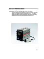
2.2
Processor
REAR PANEL
The rear panel of the Motion Corder Processor has a control panel, a connector
panel and the AC power input connector with fuses.
CONTROL PANEL
The control panel has eight
membrane push buttons that
control setup, recording and
playback.
CONNECTOR PANEL
The connector panel has a
power on indicator, different
types of trigger inputs, sync
inputs, and a video output.
POWER INPUT
The AC power input is a
standard IEC/CEE plug
connector. The KODAK
Motion Corder can be ordered
with input power of either 110
volts, 60 Hertz AC or 220
volts, 50 Hertz AC. The input
power line is fused at 6.3 Amperes. The power switch on the front panel of the
Processor turns the Motion Corder on and off.
CAUTION
The KODAK Motion Corder Analyzer must be turned off before connecting or
disconnecting the AC power cord.
REC
READY
TRIGGER
MODE STOP
MENU
ESC
ENTER
Y/CEXT IN
TRIGGER IN TRIGGER SW IN SYNC OUT VIDEO OUT
RS232C
POWER

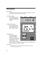
2.3
Processor Rear Panel Connectors
EXT IN
A BNC type connector that
accepts a synchronizing signal
input from an optional signal
generator, allowing the user to
control the start of each frame.
Y/C
A multipin connector that
carries the luminance and
chroma components of the
output video as separate signals.
Connect to video monitors and
VCRs equipped with the same
style video input connectors for
higher quality video.
POWER
An indicator light that illuminates when power is turned at the front panel of the
Processor.
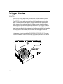
TRIGGER IN
A BNC type connector that accepts a TTL compatible signal to start or end a
recording depending upon the record mode selected. The input is connected to an
opto-isolator requiring roughly 10 milliamps drive current from a 5 volt source.
TRIGGER SW IN
A switch closure between the shield and the center conductor of this BNC type
connector will start or stop a recording depending upon the record mode selected.
SYNC OUT
A BNC type connector that provides a TTL compatible synchronizing signal at
the beginning of each picture frame.
VIDEO OUT
BNC type connector that carries the video output signal from the Motion Corder.
This output is designed to drive a 75 Ohm coaxial cable that can be connected to
a video monitor, VCR or hard copy video printer.
RS232C
A twenty five pin D subminiature connector for a serial data communication port.
This port is for connection to a remote computer and conforms to the RS232C
specification.
Y/C
EXT IN
TRIGGER IN TRIGGER SW IN SYNC OUT VIDEO OUT
RS232C
POWER

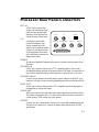
2.4
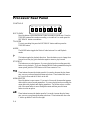
Processor Rear Panel
CONTROLS
REC READY
Press this button to place the Motion Corder in a ready to record state. Press the
TRIGGER button next to make a recording, or to return to Live mode press the
REC READY button a second time.
TRIGGER
To start a recording first press the REC READY button and then press the
TRIGGER button.
MODE
The MODE button toggles the Motion Corder between Live and Playback
modes.
This button toggles the playback direction. Press the button once to change from
forward to reverse play, press the button again to return to play forward.
STOP/ESC
This button serves a dual purpose, if you are playing back a recording press this
button to stop playback. If you are changing Motion Corder parameters using the
menu system, press the STOP button to exit from a menu to Live.
These buttons decrease the shutter speed in Live mode, decrease the play frame
rate, or move you down through the menu selections. These buttons also move
the Y reticle down and the X reticle to the left.
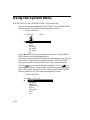
MENU/ENTER
Press this button to open a menu. If you are in Live mode, the menu that appears
deals with the various record parameters. If you are playing back a recording, the
menu deals with playback and display parameters. Use the arrow keys on either
side of the menu button to move through the menu and then press the menu
button to select an option.
These buttons increase the shutter speed in Live mode, increase the play frame
rate, or move you up through the menu selections. These buttons also move the
Y reticle up and the X reticle to the right.
REC
READY
TRIGGER
MODE
STOP
MENU
ESC
ENTER

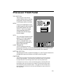
2.5
Processor Front Panel
TOP SECTION
The front panel of the Motion
Corder is broken into two sections,
the top panel carries connections
for the camera and the viewfinder.
MCDL
A nine pin D subminiature connec-
tor that accepts the cable connected
to the Multi Channel Data Link
(MCDL). The User can supply
analog and digital data to be
recorded along with the images
from the Imager.
SCSI
This is the Small Computer System
Interface (SCSI) input connector.
This connector accepts SCSI
protocol commands from a com-
puter and provides a data path for
digital video downloads.
LOOP THROUGH
A SCSI connection to the next
device on the SCSI bus, or if the Motion Corder Processor is the last device on
the SCSI bus, a termination plug should be inserted in this connector.
BOTTOM SECTION
The main power switch, a switch for the lights, a 12 volt AC power connector for
the lights and a power on indicator are located on the lower panel.
CAUTION
The 12 VAC for the lights must have at least a 75 watt but no more than 150 watt
load for proper operation. If you are using a 220 Volt AC source, you must turn
the lights ON and OFF with the light switch next to the main power switch.
If the lights do not come on, make sure that both lights are switched ON at the
lamp head and then turn the power to the lights OFF and then back ON using the
main light switch next to the power switch. The lights will not illuminate if you
turn the lamps OFF and then try to turn them back ON again using the switches at
each lamp head.
CAMERA
VIDEO OUT
DC OUT 7.5 V
MCDL
SCSI
LOOP THROUGH

2.6
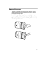
Camera
MOUNTING THE CAMERA
The camera head has four 1/4-20 threaded screw holes for mounting, one on each
side. There are two additional holes per side for a locating pin used by some
tripods. This camera head can also be mounted on the Processor by sliding the
T-Bar on any one of its sides into a matching slot along the sides or the top of
the Processor. In most situations the camera is attached to an adapter plate via
the mounting point on the bottom of the camera head. The adapter plate accepts
the camera head and two small lights.
ATTACHING THE LENS
The camera is equipped with a standard C-mount lens adapter. Insert the lens
into the threads and then rotate the lens clockwise until it stops turning with
gentle pressure. Turn the lens counterclockwise to remove it.

2.7
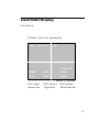
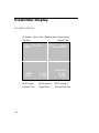
Viewfinder Display
LIVE DISPLAY
<01> 04 -15 -98 LIVE
ID Number Date or Time Operating State
1/250 START 250FPS
MCDL Digital MCDL Analog A MCDL Analog B
X:256 Y:120
Reticle X,Y Coordinates
000000 A: 000 B: 000
Exposure Time Trigger Mode Record Frame Rate

2.8
<01> 04 -15 -98 STOP
ID Number Date or Time Operating State
1/250 START 250FPS
Frame Number
Play Rate
FWD30
Elapsed Time
00001
0000.0000sec
X:256 Y:120
Reticle X,Y Coordinates
000000 A: 000 B: 000
Exposure Time Trigger Mode Record Frame Rate
MCDL Digital MCDL Analog A MCDL Analog B
Viewfinder Display
PLAYBACK DISPLAY

Chapter 3 - Operating the
Motion Corder
Getting Started
Preparing to Make a Recording
Viewing a Recording
Using the System Menu

3.1
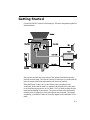
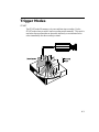
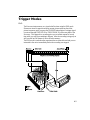
Getting Started
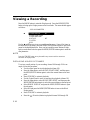
Connect the KODAK Motion Corder Analyzer, SR series components together as
illustrated below:
Plug a power cord into the lower section of the rear panel and then turn on the
power at the front panel. The Motion Corder will come up in Live mode after the
power is turned on and it has performed its self checks successfully.
When the Motion Corder is in Live the Camera video is displayed on the
viewfinder. Notice that the word Live appears in the display on the video moni-
tor to show that the processor is in Live mode. Use Live mode to adjust the lens,
tripod and the lighting for best results. The picture on the monitor is absolutely
accurate as far as composition, focus and exposure are concerned. The images
recorded by your Motion Corder will be as they appear on the viewfinder in Live
mode.
La pagina si sta caricando...
La pagina si sta caricando...
La pagina si sta caricando...
La pagina si sta caricando...
La pagina si sta caricando...
La pagina si sta caricando...
La pagina si sta caricando...
La pagina si sta caricando...
La pagina si sta caricando...
La pagina si sta caricando...
La pagina si sta caricando...
La pagina si sta caricando...
La pagina si sta caricando...
La pagina si sta caricando...
La pagina si sta caricando...
La pagina si sta caricando...
La pagina si sta caricando...
La pagina si sta caricando...
La pagina si sta caricando...
La pagina si sta caricando...
La pagina si sta caricando...
La pagina si sta caricando...
La pagina si sta caricando...
La pagina si sta caricando...
La pagina si sta caricando...
La pagina si sta caricando...
La pagina si sta caricando...
La pagina si sta caricando...
La pagina si sta caricando...
La pagina si sta caricando...
La pagina si sta caricando...
La pagina si sta caricando...
La pagina si sta caricando...
La pagina si sta caricando...
La pagina si sta caricando...
La pagina si sta caricando...
La pagina si sta caricando...
La pagina si sta caricando...
La pagina si sta caricando...
La pagina si sta caricando...
La pagina si sta caricando...
La pagina si sta caricando...
La pagina si sta caricando...
La pagina si sta caricando...
La pagina si sta caricando...
La pagina si sta caricando...
La pagina si sta caricando...
La pagina si sta caricando...
La pagina si sta caricando...
-
 1
1
-
 2
2
-
 3
3
-
 4
4
-
 5
5
-
 6
6
-
 7
7
-
 8
8
-
 9
9
-
 10
10
-
 11
11
-
 12
12
-
 13
13
-
 14
14
-
 15
15
-
 16
16
-
 17
17
-
 18
18
-
 19
19
-
 20
20
-
 21
21
-
 22
22
-
 23
23
-
 24
24
-
 25
25
-
 26
26
-
 27
27
-
 28
28
-
 29
29
-
 30
30
-
 31
31
-
 32
32
-
 33
33
-
 34
34
-
 35
35
-
 36
36
-
 37
37
-
 38
38
-
 39
39
-
 40
40
-
 41
41
-
 42
42
-
 43
43
-
 44
44
-
 45
45
-
 46
46
-
 47
47
-
 48
48
-
 49
49
-
 50
50
-
 51
51
-
 52
52
-
 53
53
-
 54
54
-
 55
55
-
 56
56
-
 57
57
-
 58
58
-
 59
59
-
 60
60
-
 61
61
-
 62
62
-
 63
63
-
 64
64
-
 65
65
-
 66
66
-
 67
67
-
 68
68
-
 69
69


in altre lingue
- English: Kodak SR series User manual
Documenti correlati
Altri documenti
-
IK Multimedia iRig Keys Pro Manuale utente
-
IK Multimedia irig mic cast Manuale utente
-
Sanyo POAMD07MCI - Digital AV Player Install And Operation Instructions
-
-
-
Hitachi VM-E530A Istruzioni per l'uso
-
-
Canon VIXIA HF R82 Manuale utente
-
Tyco ADEMD4B000TVS Manuale utente
-
Atlantis NetDVR V400 Manuale utente