ABB MicroFlex e190 Quick Installation Manual
- Tipo
- Quick Installation Manual

English . . . . . . . . . . . . . . 3
Deutsch . . . . . . . . . . . . 11
Español . . . . . . . . . . . . 19
Français . . . . . . . . . . . . 27
Italiano . . . . . . . . . . . . . 35
Português (Brasil) . . . . 43
Suomi. . . . . . . . . . . . . .51
Svenska . . . . . . . . . . . .59
Türkçe . . . . . . . . . . . . . 67
Русский . . . . . . . . . . . . 75
中文 . . . . . . . . . . . . . . . 83
ABB motion control
Quick installation guide
MicroFlex e190 servo drive
E190QuickStartGuide.book Page 1 Thursday, May 18, 2017 10:40 AM

List of related manuals in English
You can find manuals and other product documents in PDF format on the Internet. See section
Document library on the Internet on the inside of the back cover. For manuals not available in the
Document library, contact your local ABB representative.
3AXD50000037325 Rev C
MUL
EFFECTIVE: 2017-05-01
© 2017 ABB Oy. All Rights Reserved.
Drive hardware manuals and guides Code (English)
MicroFlex e190 User’s manual 3AXD50000037326
MicroFlex e190 Wall chart 3AXD50000037323
Certificates
MicroFlex e190 EU Single Declaration of Conformity 3AXD10000540159
MicroFlex e190 STO (TÜV) Certificate 3AXD10000540318
MicroFlex e190 UL Certificate 3AXD10000540319
Accessories
OPT-MF-201 Resolver Adapter 3AUA0000168681
E190QuickStartGuide.book Page 2 Thursday, May 18, 2017 10:40 AM

Quick installation guide - MicroFlex e190
3
Quick installation guide -
MicroFlex e190
Introduction
This guide contains the very basic information
about the mechanical and electrical installation
of the MicroFlex e190 drive module. For
complete documentation see the
MicroFlex e190 User’s Manual (code:
3AXD50000037326 [English]).
Safety instructions
WARNING! All electrical
installation and maintenance work on
the drive should be carried out by
qualified electricians only.
WARNING! Operation of this
equipment requires detailed
installation and operation instructions
provided in the Installation/Operation
manual intended for use with this product. It
should be retained with this device at all times.
A hard copy of this information may be ordered
at +358 10 22 11 or your local ABB sales office.
Never work on the drive, the braking chopper
circuit, the motor cable or the motor when input
power is applied to the drive. After
disconnecting input power, always wait for 5
minutes to let the intermediate circuit
capacitors discharge before you start working
on the drive, control cabling, motor or motor
cable. Even when input power is not applied to
the drive, externally supplied control circuits
may carry dangerous voltages. Always ensure
by measuring that no voltage is actually
present.
• A rotating permanent magnet motor can
generate a dangerous voltage. Lock the
motor shaft mechanically before connecting
a permanent magnet motor to the drive, and
before doing any work on a drive system
connected to a permanent magnet motor.
• The MicroFlex e190 is an IP20 (UL open
type) drive to be used in a heated, indoor
controlled environment. The drive must be
installed in clean air according to enclosure
classification. Cooling air must be clean, free
from corrosive materials and electrically
conductive dust. See the User’s Manual for
detailed specifications.
• The MicroFlex e190 must be installed where
the pollution degree according to UL and EN
61800-5-1 shall not exceed 2.
• The maximum ambient air temperature is:
1.6 A model
: 45 °C (113 °F) at rated current.
The current is derated for 45 to 50 °C (113 to
122 °F). See user’s manual.
3 A - 9 A models
: 55 °C (131 °F) at rated
current. No current derating is required.
• Motor overtemperature sensing is not
provided by the drive.
• The drive is suitable for use in a circuit
capable of delivering not more than 5,000
rms symmetrical amperes, 240 V maximum,
when protected by CC class fuses, rated
max. 20 A.
• The cables located within the motor circuit
must be rated for at least 75 °C (167 °F) in
UL-compliant installations.
• Use 75 °C copper wiring only.
• The input cable must be protected with
fuses. Suitable IEC (class gG) and UL (class
CC) fuses are listed in the Technical data
section of the MicroFlex e190 User’s
Manual.
• Integral solid state short circuit protection
does not provide branch circuit protection.
For installation in the United States, branch
circuit protection must be provided in
accordance with the National Electrical Code
(NEC) and any applicable local codes. To
fulfill this requirement, use the UL classified
fuses.
E190QuickStartGuide.book Page 3 Thursday, May 18, 2017 10:40 AM

Quick installation guide - MicroFlex e190
4
• For installation in Canada, branch circuit
protection must be provided in accordance
with Canadian Electrical Code and any
applicable provincial codes. To fulfill this
requirement, use the UL classified fuses.
• For use in Canada: Transient surge
suppression shall be installed on the line side
of this equipment and shall be rated 240 V
(phase to ground), 240 V (phase to phase),
suitable for overvoltage category III, and
shall provide protection for a rated impulse
withstand voltage peak of 2.5 kV.
• The drive provides overload protection in
accordance with the National Electrical Code
(NEC). See the User’s Manual for overload
protection settings.
• The drive can provide an overload current of
300% of rated current for a maximum of 3 s.
See user manual.
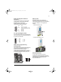
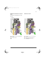
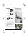
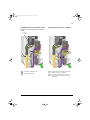
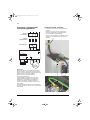
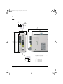
Mechanical installation
Fasten the drive module to the mounting base
using screws through the two mounting holes.
E190QuickStartGuide.book Page 4 Thursday, May 18, 2017 10:40 AM

Quick installation guide - MicroFlex e190
5
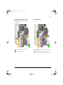
Dimensions
72
(2.83)
155
(6.10)
200*
(7.87)
7
(0.28)
5
(0.2)
6
(0.24)
188.4
(7.42)
200
(7.87)
223*
(8.78)
Ø 5
(0.20)
5
(0.20)
5
(0.20)
Ø 12
(0.47)
* Approximate dimensions. Allow extra
space for feedback and other control
cables.
Weights:
1.6A: 1.65kg (3.64lb)
3A: 1.70kg (3.75lb)
6A: 1.75kg (3.86lb)
9A: 1.75kg (3.86lb)
E190QuickStartGuide.book Page 5 Thursday, May 18, 2017 10:40 AM

Quick installation guide - MicroFlex e190
6
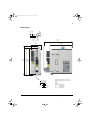
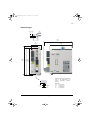
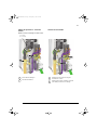
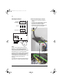
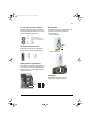
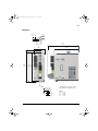
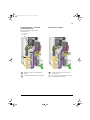
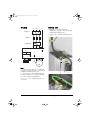
Electrical installation
Notes:
(1) If shielded supply (input) cable is used, and
the conductivity of the shield is less than 50%
of the conductivity of a phase conductor, use a
cable with a ground conductor or a separate PE
cable.
(2) For motor cabling, use a separate ground
cable if the conductivity of the motor cable
shield is less than 50% of that of a phase
conductor and the cable has no symmetrical
ground conductors.
(3) MicroFlex e190 can be powered from a DC
supply. See user’s manual.
Power cabling: input
• Attach the included terminal blocks to the
drive.
• Connect the supply, resistor (if present) and
motor cables to the appropriate terminals of
the drive.
• Strip the power cables so that the shields are
bare at the cable clamps.
MicroFlex e190 L1 L2 L3
L1/L L2/N L3
UPE
PE
PE
PE
(3)
(2)
VW
U
V
W
R- R+ PE
UDC- UDC+
Isolating switch
Fuses
Filter
Braking
resistor
3~
Motor
0.5...0.6 N·m
(4.4...5.3 lbf·in)
E190QuickStartGuide.book Page 6 Thursday, May 18, 2017 10:40 AM

Quick installation guide - MicroFlex e190
7
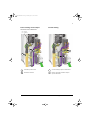
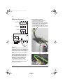
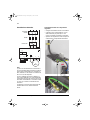
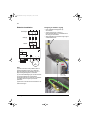
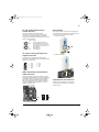
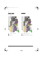
Power cabling: motor output
Ground the motor cable shield.
Control cabling
1
0.5...0.6 N·m
(4.4...5.3 lbf·in)
2
Cable clamp on bare shield.
PE/Ground connection.
1
2
4
Use shrink tubing or tape to contain strands.
Remove outer jacket of cable at clamp to
expose cable screen
3
4
3
E190QuickStartGuide.book Page 7 Thursday, May 18, 2017 10:40 AM

Quick installation guide - MicroFlex e190
8
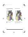
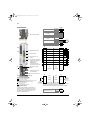
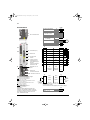
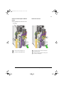
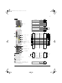
Wire sizes and tightening torques:
X1A: Dinkle EC762V-B3253206P-BK
X1B: Dinkle EC762V-B3253203P-BK
0.2...6.0 mm
2
(30*...10 AWG)
* Minimum size for UL installations is 14 AWG.
Torque: 0.7 N·m (6.2 lbf·in)
X2
: Phoenix Contact MVSTBR 2,5HC/ 2-ST-5,08
0.2...2.5 mm
2
(24...12 AWG)
Torque: 0.6 N·m (5.3 lbf·in)
X3, X4: Weidmüller B2L 3.50/20/180,
Weidmüller B2L 3.50/8/180
0.2...1.0 mm
2
(28...16 AWG)
Notes:
The wiring shown is for demonstrative purposes only.
Complete information for all connectors, including X7
and X8, is provided in MicroFlex e190 User’s Manual
(code: 3AXD500000373236).
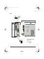
E1/E2
Ethernet fieldbus
IN E2
OUT
E1
X1A
115...240 V AC ±10%
input
L1 1
L2 2
L3 3
DC bus-
UDC-
4
Brake resistor
R-
5
DC bus+ / Brake res.
R+/UDC+
6
X1B
Motor output
U1
V2
W3
E3
Ethernet host (PC)
1
X3 X3
1
Status-/DO0- Status-/DO0+
11
2 DO2- DO2+ 12
3 DO1- DO1+ 13
4 DI2- DI2+ 14
5 DI3- DI3+ 15
6 DI1- DI1+ 16
7 DI0- DI0+ 17
8AGND AO0 18
9AI0- AI0+19
10 Shield Shield 20
E2
Connectors
E1
X1A
X1B
E3
X3
X4
X8
X7
X2
SW2
Universal encoder input
supports multiple
feedback types.
See MicroFlex e190
User’s Manual.
X4 X4
1
STO1 STO1
11
2 STO2 STO2 12
3SGND SGND13
4 24 V out 24 V out 14
Safe Torque Off: Both circuits must be closed for the drive to start.
All connections are duplicated for easy wiring.
X2
(Optional) External
power input: 24 V, 1 A
0 V 1
+24 V IN 2
M
Example:
STO input
using internal
24 V supply
Example:
STO input
using external
24 V supply
Safe Torque Off
Input/ Output
Ethernet fieldbus
Incremental encoder
in/out
X8 voltage selector
Optional 24 V supply
Ethernet host (PC)
E190QuickStartGuide.book Page 8 Thursday, May 18, 2017 10:40 AM

Quick installation guide - MicroFlex e190
9
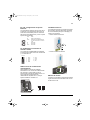
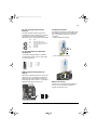
E1 / E2: Ethernet port configuration
The rotary switches are read once at start-up.
The switches select the mode of operation for
the E1 and E2 Ethernet fieldbus connectors on
the top panel of the drive.
X7: Incremental encoder in / out
The secondary incremental encoder input/
output connection provides A/B channels and a
Z index channel.
SW2: feedback supply voltage
SW2 sets the supply output voltage on
feedback connector X8, pin 12. Check that the
correct output voltage is selected. Most
feedback devices require 5 V, but some
Hiperface devices require 8 V.
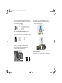
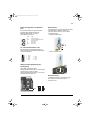
Memory unit
The memory unit is an essential part of the
drive and must always be fitted. It is not
designed for frequent removal and insertion.
• Open the memory unit:
• Insert the memory unit:
User’s manual
Continue with drive start-up according to the
instructions in MicroFlex e190 User’s Manual.
1
2
3
4
5
CHA+
CHB+
CHZ+
(NC)
GND
6
7
8
9
CHA-
CHB-
CHZ-
(NC)
Value Mode
00 EtherCAT slave mode
01-EF Ethernet POWERLINK CN mode:
selected value is the node ID
F0 Reserved
F1 Reserved
F2-FF Reserved
Pin 1
SW2
5 V 8 V
1
2
E190QuickStartGuide.book Page 9 Thursday, May 18, 2017 10:40 AM

Quick installation guide - MicroFlex e190
10
E190QuickStartGuide.book Page 10 Thursday, May 18, 2017 10:40 AM

Kurzanleitung für die Installation des MicroFlex e190
11
Kurzanleitung für die
Installation des MicroFlex e190
Einleitung
Diese Anleitung enthält allgemeine
Informationen zur mechanischen und
elektrischen Installation des
Frequenzumrichtermoduls MicroFlex e190. Die
vollständige Dokumentation finden Sie im
Benutzerhandbuch MicroFlex e190 (Code:
3AXD50000037326 [Englisch]).
Sicherheitsvorschriften
WARNUNG! Alle elektrischen
Installations- und Wartungsarbeiten
am Frequenzumrichter dürfen nur
von qualifiziertem Fachpersonal
ausgeführt werden.
WARNUNG! Vor dem Betrieb
dieses Gerätes müssen die
detaillierten Installations- und
Betriebsan-leitungen gelesen und
verstanden worden sein, die im Installations-/
Betriebshandbuch für die Bedienung dieses
Produkts enthalten sind. Dieses Handbuch
sollte jederzeit in der Nähe dieses Gerätes
aufbewahrt werden. Eine Kopie dieser
Anleitungen können Sie unter Tel. +358 10 22
11 oder bei Ihrer lokalen ABB-Vertriebsstelle
bestellen.
Arbeiten Sie niemals am Frequenzumrichter,
dem Bremschopper-Stromkreis, dem
Motorkabel oder dem Motor, wenn der
Frequenzumrichter an die
Spannungsversorgung angeschlossen ist.
Warten Sie nach der Trennung von der
Spannungsversorgung 5 Minuten, bis die
Zwischenkreis-Kondensatoren entladen sind,
bevor Sie mit den Arbeiten am
Frequenzumrichter, den Steuerkabeln, dem
Motor oder den Motorkabeln beginnen. Extern
gespeiste Steuerkreise können im
Frequenzumrichter auch dann gefährliche
Spannungen führen, wenn die
Spannungsversorgung des
Frequenzumrichters abgeschaltet ist. Stellen
Sie durch Messung sicher, dass keine
Spannungen anliegen.
• Ein drehender Permanentmagnetmotor kann
gefährliche Spannung erzeugen. Die
Motorwelle muss mechanisch blockiert
werden, bevor ein Permanentmagnetmotor
an den Frequenzumrichter angeschlossen
und bevor Arbeiten an einem Antriebssystem
ausgeführt werden, das an einem
Permanentmagnetmotor angeschlossen ist.
• Der MicroFlex e190 ist ein IP20- (UL-Typ
offen) Frequenzumrichter zur Verwendung in
beheizten und überwachten Innenräumen.
Der Frequenzumrichter muss in sauberer
Luft gemäß der Gehäuseklassifizierung
installiert werden. Die Kühlluft muss sauber,
frei von korrosiven Materialien und elektrisch
leitfähigem Staub sein. Detaillierte
Spezifikationen enthält das
Benutzerhandbuch.
• Der MicroFlex e190 darf nur dort installiert
werden, wo der Verschmutzungsgrad nach
UL und EN 61800-5-1 Grad 2 nicht
überschreitet.
• Die maximale Umgebungstemperatur
beträgt:1,6 A-Ausführung
: 45 °C (113 °F) bei
Nennstromstärke. Die Stromstärke wird bei
45 bis 50 °C (113 bis 122 °F) gemindert.
Siehe Benutzerhandbuch.
Ausführungen mit 3 A - 9 A
: 55 °C (131 °F)
bei Nennstromstärke. Es ist kein Strom-
Derating erforderlich.
• Der Frequenzumrichter ist nicht mit
Sensoren ausgestattet, die eine
Übertemperatur des Motors feststellen.
• Der Frequenzumrichter ist für den Einsatz in
Schaltkreisen geeignet, die bei einer
maximalen Spannung von 240 V einen
symmetrischen Strom von nicht mehr als
5.000 Ampere (Effektivwert) erreichen und
durch eine Sicherung Class CC, max.
Nennstrom 20 A, geschützt sind.
E190QuickStartGuide.book Page 11 Thursday, May 18, 2017 10:40 AM

Kurzanleitung für die Installation des MicroFlex e190
12
• Die Kabel im Motorschaltkreis müssen für
mindestens 75 °C (167 °F) in Installationen
nach UL-Standard ausgelegt sein.
• Nur 75-°C-Kupferleitung verwenden.
• Das Eingangskabel muss mit Sicherungen
geschützt sein. Geeignete IEC- (Klasse gG)
und UL- (Klasse CC) Sicherungen sind im
Kapitel Technische Daten des
Benutzerhandbuches MicroFlex e190
aufgelistet.
• Der integrierte Halbleiter-Kurzschlussschutz
bietet keinen Schutz für Zweigstromkreise.
Installationen in den USA erfordern einen
Zweigstromkreis-Schutz nach dem National
Electrical Code (NEC) und die Einhaltung
aller anzuwendenden örtlichen Vorschriften.
Zur Erfüllung dieser Anforderungen sind UL-
klassifizierte Sicherungen zu verwenden.
• Installationen in Kanada erfordern einen
Zweigstromkreis-Schutz gemäß Canadian
Electrical Code und die Einhaltung aller
anzuwendenden örtlichen Vorschriften. Zur
Erfüllung dieser Anforderungen sind UL-
klassifizierte Sicherungen zu verwenden.
• Für den Einsatz in Kanada: Auf der
Leitungsseite dieses Geräts ist ein
transienter Überspannungsschutz mit einer
Bemessung von 240 V (Phase gegen
Masse), 240 V (Phase gegen Phase) zu
installieren, der für die Überspannungs-
kategorie III geeignet ist und Schutz vor
Bemessungsstoßspannungsspitzen von
2,5 kV bietet.
• Der Frequenzumrichter bietet einen
Überlastschutz gemäß National Electrical
Code (NEC). Angaben zu den erforderlichen
Einstellungen für den Überlastschutz enthält
das Benutzerhandbuch.
• Der Frequenzumrichter kann einen
Überlaststrom von 300 % des Nennstroms
für maximal 3 s erzeugen.
Siehe Benutzerhandbuch.
Mechanische Installation
Befestigen Sie das Frequenzumrichtermodul
auf der Montagebasis durch Verschraubung an
den vorgesehenen zwei Montagebohrungen.
E190QuickStartGuide.book Page 12 Thursday, May 18, 2017 10:40 AM

Kurzanleitung für die Installation des MicroFlex e190
13
Abmessungen
72
(2.83)
155
(6.10)
200*
(7.87)
7
(0.28)
5
(0.2)
6
(0.24)
188.4
(7.42)
200
(7.87)
223*
(8.78)
Ø 5
(0.20)
5
(0.20)
5
(0.20)
Ø 12
(0.47)
* Ungefähre Abmessungen. Zusätzlichen
Raum für die Rückkopplungs- und
anderen Steuerkabel gewähren.
Gewichte:
Gewichte:
1,6A: 1,65kg (3,64lb)
3A: 1,70kg (3,75lb)
6A: 1,75kg (3,86lb)
9A: 1,75kg (3,86lb)
E190QuickStartGuide.book Page 13 Thursday, May 18, 2017 10:40 AM

Kurzanleitung für die Installation des MicroFlex e190
14
Elektrische Installation
Hinweise:
(1) Werden geschirmte Netz- (Versorgungs-)
Kabel verwendet und ist die Leitfähigkeit des
Schirms kleiner als 50 % der Leitfähigkeit des
Phasenleiters, benutzen Sie ein Kabel mit
einem Erdungsleiter oder ein separates PE-
Kabel.
(2) Für den Motorkabelanschluss ist ein
separates Erdungskabel zu verwenden, wenn
die Leitfähigkeit des Motorkabelschirms
geringer als 50 % der Leitfähigkeit der
Phasenleiter ist und das Kabel keinen
symmetrischen Erdungsleiter besitzt.
(3) Der MicroFlex e190 kann von einer
Gleichstromversorgung gespeist werden.
Siehe Benutzerhandbuch.
Leistungskabel: Eingang
• Die beiliegenden Klemmenblöcke am
Frequenzumrichter befestigen.
• Einspeise-, Widerstands- (falls vorhanden)
und Motorkabel an die jeweiligen Klemmen
des Frequenzumrichters anschließen.
• Die Leistungskabel so abisolieren, dass die
Schirme an den Kabelschellen blank liegen.
MicroFlex e190 L1 L2 L3
L1/L L2/N L3
UPE
PE
PE
PE
(3)
(2)
VW
U
V
W
R- R+ PE
UDC- UDC+
Trennschalter
Sicherungen
Netzfilter
Bremswiderstand
3~
Motor
0,5 - 0,6 Nm
(4,4 - 5,3 lbf·in)
E190QuickStartGuide.book Page 14 Thursday, May 18, 2017 10:40 AM

Kurzanleitung für die Installation des MicroFlex e190
15
Leistungskabel: Motorausgang
Erdung der Motorkabelabschirmung.
Steuerkabelanschlüsse
1
0,5 - 0,6 Nm
(4,4 - 5,3 lbf·in)
2
Kabelschelle über dem blanken Schirm.
PE-/Erdungsanschluss.
1
2
4
Schirmlitzen mit Schrumpfschlauch oder
Isolierband zusammenhalten.
Isoliermantel im Bereich der Schelle entfernen
und den Kabelschirm freilegen.
3
4
3
E190QuickStartGuide.book Page 15 Thursday, May 18, 2017 10:40 AM

Kurzanleitung für die Installation des MicroFlex e190
16
Kabelgrößen und Anzugsmomente:
X1A
: Dinkle EC762V-B3253206P-BK
X1B
: Dinkle EC762V-B3253203P-BK
0,2...6,0 mm
2
(30*...10 AWG)
* Die Mindestgröße für UL-Anlagen ist 14 AWG.
Drehmoment: 0,7 Nm (6,2 lbf·in)
X2
: Phoenix Contact MVSTBR 2,5HC/ 2-ST-5,08
0,2...2,5 mm
2
(24...12 AWG)
Drehmoment: 0,6 Nm (5,3 lbf·in)
X3, X4
: Weidmüller B2L 3.50/20/180, Weidmüller B2L
3.50/8/180
0,2...1,0 mm
2
(28...16 AWG)
Hinweise:
Gezeigte Anschlüsse dienen nur als Beispiel. Vollständige
Informationen für alle Anschlüsse, einschließlich X7 und X8, sind im
Benutzerhandbuch MicroFlex e190 (Code: 3AXD500000373236)
zu finden.
E1/E2
Ethernet-Feldbus
IN E2
OUT
E1
X1A
115...240 V ±10%
Wechselstromeingang
L1 1
L2 2
L3 3
DC-Bus-
UDC-
4
Bremswiderstand
R-
5
DC-Bus+ /
Bremswiderstand
R+/UDC+
6
X1B
Motoranschluss
U1
V2
W3
E3
Ethernet-Host (PC)
1
X3 X3
1
Status-/DO0- Status-/DO0+
11
2 DO2- DO2+ 12
3 DO1- DO1+ 13
4 DI2- DI2+ 14
5 DI3- DI3+ 15
6 DI1- DI1+ 16
7 DI0- DI0+ 17
8AGND AO0 18
9AI0- AI0+19
10 Abschirmung Abschirmung 20
E2
Stecker
E1
X1A
X1B
E3
X3
X4
X8
X7
X2
SW2
Der Universal-
Encodereingang
unterstützt mehrere
Rückkopplungsarten.
Siehe Benutzerhandbuch
MicroFlex e190.
X4 X4
1
STO1 STO1
11
2 STO2 STO2 12
3SGND SGND13
4 24 V out 24 V out 14
Safe Torque Off: Beide Kreise müssen zum Start des
Frequenzumrichters geschlossen sein.
Alle Verbindungen sind zur einfacheren Verkabelung dupliziert.
X2
(Optional) Externer Spannungs-
versorgungseingang: 24 V, 1 A
0 V 1
+24 V IN 2
M
Beispiel:
STO-Eingang
mit interner
24-V-
Versorgung
Beispiel:
STO-Eingang mit
externer 24-V-
Versorgung
Safe Torque Off (Sicher
abgeschaltetes Moment)
Eingang/Ausgang
Ethernet-Feldbus
Inkrementalgeber
Eingang/Ausgang
X8 Spannungswähler
24-V-Versorgung
(optional)
Ethernet-Host (PC)
E190QuickStartGuide.book Page 16 Thursday, May 18, 2017 10:40 AM

Kurzanleitung für die Installation des MicroFlex e190
17
E1/E2: Konfiguration Ethernet-
Anschluss
Die Drehschalter werden beim Einschalten
einmal gelesen. Die Schalter wählen den
Betriebsmodus für die Ethernet-
Feldbusanschlüsse E1 und E2 an der
Oberseite des Frequenzumrichters.
X7: Inkrementalgeber In/Out
Der Sekundäranschluss am Eingang/Ausgang
des Inkremental-Encoders bietet die Kanäle A/
B und einen Z-Indexkanal.
SW2: Versorgungsspannung
Rückkopplung
SW2 stellt die Versorgungsausgangsspannung
am Rückkopplungsstecker X8, Stift 12 ein.
Stellen Sie sicher, dass die richtige
Ausgangsspannung ausgewählt ist. Für die
meisten Drehgebergeräte sind 5 V erforderlich,
für bestimmte Hiperface-Geräte jedoch 8 V.
Memory Unit
Die Memory Unit ist eine wesentliche
Komponente des Frequenzumrichters und
muss stets eingebaut sein. Sie ist nicht darauf
ausgelegt, häufig aus- und eingebaut zu
werden.
• Öffnen der Memory Unit:
• Einsetzen der Memory Unit:
Benutzerhandbuch
Im Anschluss an die hier in Kurzform
dargestellten Installationsarbeiten erfolgt die
Inbetriebnahme des Frequenzumrichters nach
den Anweisungen des MicroFlex e190
Benutzerhandbuches.
1
2
3
4
5
CHA+
CHB+
CHZ+
(NC)
GND
(Erdg.)
6
7
8
9
CHA-
CHB-
CHZ-
(NC)
Wert Modus
00 EtherCAT-Slavemodus
01-EF Ethernet POWERLINK CN-Mo-
dus: Der ausgewählte Wert ist die
Knoten-ID.
F0 Reserviert
F1 Reserviert
F2-FF Reserviert
Pin 1
SW2
5 V 8 V
1
2
E190QuickStartGuide.book Page 17 Thursday, May 18, 2017 10:40 AM

Kurzanleitung für die Installation des MicroFlex e190
18
E190QuickStartGuide.book Page 18 Thursday, May 18, 2017 10:40 AM

Guía de instalación rápida - MicroFlex e190
19
Guía de instalación rápida
- MicroFlex e190
Introducción
La presente guía contiene información básica
sobre la instalación mecánica y eléctrica del
módulo de convertidor de frecuencia
MicroFlex . Consulte el Manual de usuario
MicroFlex e190 User’s Manual si desea
información más detallada (código:
3AXD50000037326 [English]).
Instrucciones de seguridad
¡ADVERTENCIA! Todos los
trabajos eléctricos de instalación y
mantenimiento deben ser realizados,
única y exclusivamente, por
electricistas cualificados.
ADVERTENCIA!
El funcionamiento de este equipo
requiere una instalación detallada e
instrucciones de funcionamiento
facilitadas junto con el manual de Instalación/
Funcionamiento para su uso con el presente
producto. Debe estar adjunto con este
dispositivo en todo momento. Puede pedir una
copia impresa de esta información llamando al
+358 10 22 11 o en su oficina de ventas ABB
local.
No realizar nunca trabajos sobre el
accionamiento, el circuito de control de freno, el
cable del motor o el motor mientras esté
conectado a la fuente de alimentación. Tras
desconectar la alimentación de entrada, espere
siempre 5 minutos a que se descarguen los
condensadores del circuito intermedio antes de
trabajar en el convertidor de frecuencia, los
cables de control, el motor o el cable a motor. Los
circuitos de control alimentados de forma externa
pueden conducir tensión peligrosa incluso con la
alimentación de entrada del convertidor
desconectada. Asegúrese siempre, mediante
medición, de que no existe tensión activa.
• Un motor de imanes permanentes en
rotación puede generar un voltaje peligroso.
Enclave mecánicamente el eje del motor
antes de conectar un motor magnético
permanente al accionamiento, y antes de
hacer cualquier trabajo en un sistema de
accionamiento conectado a un motor
magnético permanente.
• El MicroFlex e190 es un accionamiento IP20
(UL tipo abierto) para su uso en un entorno
interior, controlado y calefactado. El
accionamiento se debe instalar en una
atmósfera limpia de conformidad con la
clasificación del recinto. El aire de
refrigeración debe estar limpio, libre de
materiales corrosivos y polvo conductor de
electricidad. Consulte el Manual de usuario
si desea especificaciones detalladas.
• El MotiFlex e190 debe instalarse en un
entorno donde el nivel de contaminación no
sea mayor que 2 según UL y la norma EN
61800-5-1.
• La temperatura ambiente máxima es:
Modelo 1,6 A
: 45 °C (113 °F) para corriente
nominal. La corriente se reduce para 45 a
50 °C (113 a 122 °F). Consulte el manual de
usuario.
Modelos 3 A - 9 A
: 55 °C (131 °F) para
corriente nominal. No es necesario
reducción de corriente.
• El accionamiento no esta provisto de un
sistema de detección de sobrecalentamiento
del motor.
• El accionamiento es adecuado para su uso
en un circuito de no más de 5.000 amperios
RMS simétricos, máximo 240 V, con
protección de fusibles clase CC, clasificado
como máximo para 20 A.
• El rango de los cables situados en el circuito
del motor debe resistir al menos 75 °C
(167 °F) en instalaciones bajo cumplimiento
de requisitos UL.
• Utilice solo cableado de cobre de 75 °C
(167 °F).
E190QuickStartGuide.book Page 19 Thursday, May 18, 2017 10:40 AM

Guía de instalación rápida - MicroFlex e190
20
• El cable de entrada debe protegerse con
fusibles. Se incluye una lista de fusibles IEC
(clase gG) y UL (clase CC) adecuados en la
sección Datos técnicos del Manual de
usuario MicroFlex e190.
• La protección integral contra cortocircuitos
de estado sólido no proporciona protección
de circuitos derivados. Para la instalación en
Estados Unidos, se deberá proporcionar
protección para cada rama del circuito de
conformidad con el Código Eléctrico
Nacional de Estados Unidos (NEC) y con
cualquier normativa local aplicable. Para
satisfacer este requerimiento, deben
emplearse fusibles bajo clasificación UL.
• Para la instalación en Canadá, deberá
proveerse protección para cada rama del
circuito de acuerdo con el Código Eléctrico
Canadiense así como con cualquier otro
código provincial aplicable. Para satisfacer
este requerimiento, deben emplearse
fusibles bajo clasificación UL.
• Para uso en Canadá: la supresión de
sobretensiones transitorias se debe instalar
en el lado de la línea de este equipo y debe
estar clasificado para 240 V (fase a tierra),
240 V (fase a fase), adecuado para la
categoría de sobretensión III y debe
proporcionar protección contra una cresta de
tensión asignada soportada al impulso de
2,5 kV.
• El accionamiento incorpora protección frente
a sobrecarga de acuerdo con el Código
Eléctrico Nacional (NEC). Consulte el
Manual de usuario para configurar la
protección frente a sobrecarga.
• El accionamiento puede proporcionar una
corriente de sobrecarga del 300 % de
corriente asignada durante como máximo 3
segundos. Consulte el manual de usuario.
Instalación mecánica
Sujete el módulo del convertidor a la base de
montaje introduciendo los tornillos a través de
los dos orificios de montaje.
E190QuickStartGuide.book Page 20 Thursday, May 18, 2017 10:40 AM
La pagina sta caricando ...
La pagina sta caricando ...
La pagina sta caricando ...
La pagina sta caricando ...
La pagina sta caricando ...
La pagina sta caricando ...
La pagina sta caricando ...
La pagina sta caricando ...
La pagina sta caricando ...
La pagina sta caricando ...
La pagina sta caricando ...
La pagina sta caricando ...
La pagina sta caricando ...
La pagina sta caricando ...
La pagina sta caricando ...
La pagina sta caricando ...
La pagina sta caricando ...
La pagina sta caricando ...
La pagina sta caricando ...
La pagina sta caricando ...
La pagina sta caricando ...
La pagina sta caricando ...
La pagina sta caricando ...
La pagina sta caricando ...
La pagina sta caricando ...
La pagina sta caricando ...
La pagina sta caricando ...
La pagina sta caricando ...
La pagina sta caricando ...
La pagina sta caricando ...
La pagina sta caricando ...
La pagina sta caricando ...
La pagina sta caricando ...
La pagina sta caricando ...
La pagina sta caricando ...
La pagina sta caricando ...
La pagina sta caricando ...
La pagina sta caricando ...
La pagina sta caricando ...
La pagina sta caricando ...
La pagina sta caricando ...
La pagina sta caricando ...
La pagina sta caricando ...
La pagina sta caricando ...
La pagina sta caricando ...
La pagina sta caricando ...
La pagina sta caricando ...
La pagina sta caricando ...
La pagina sta caricando ...
La pagina sta caricando ...
La pagina sta caricando ...
La pagina sta caricando ...
La pagina sta caricando ...
La pagina sta caricando ...
La pagina sta caricando ...
La pagina sta caricando ...
La pagina sta caricando ...
La pagina sta caricando ...
La pagina sta caricando ...
La pagina sta caricando ...
La pagina sta caricando ...
La pagina sta caricando ...
La pagina sta caricando ...
La pagina sta caricando ...
La pagina sta caricando ...
La pagina sta caricando ...
La pagina sta caricando ...
La pagina sta caricando ...
La pagina sta caricando ...
La pagina sta caricando ...
La pagina sta caricando ...
La pagina sta caricando ...
-
 1
1
-
 2
2
-
 3
3
-
 4
4
-
 5
5
-
 6
6
-
 7
7
-
 8
8
-
 9
9
-
 10
10
-
 11
11
-
 12
12
-
 13
13
-
 14
14
-
 15
15
-
 16
16
-
 17
17
-
 18
18
-
 19
19
-
 20
20
-
 21
21
-
 22
22
-
 23
23
-
 24
24
-
 25
25
-
 26
26
-
 27
27
-
 28
28
-
 29
29
-
 30
30
-
 31
31
-
 32
32
-
 33
33
-
 34
34
-
 35
35
-
 36
36
-
 37
37
-
 38
38
-
 39
39
-
 40
40
-
 41
41
-
 42
42
-
 43
43
-
 44
44
-
 45
45
-
 46
46
-
 47
47
-
 48
48
-
 49
49
-
 50
50
-
 51
51
-
 52
52
-
 53
53
-
 54
54
-
 55
55
-
 56
56
-
 57
57
-
 58
58
-
 59
59
-
 60
60
-
 61
61
-
 62
62
-
 63
63
-
 64
64
-
 65
65
-
 66
66
-
 67
67
-
 68
68
-
 69
69
-
 70
70
-
 71
71
-
 72
72
-
 73
73
-
 74
74
-
 75
75
-
 76
76
-
 77
77
-
 78
78
-
 79
79
-
 80
80
-
 81
81
-
 82
82
-
 83
83
-
 84
84
-
 85
85
-
 86
86
-
 87
87
-
 88
88
-
 89
89
-
 90
90
-
 91
91
-
 92
92


ABB MicroFlex e190 Quick Installation Manual
- Tipo
- Quick Installation Manual
in altre lingue
- English: ABB MicroFlex e190
- français: ABB MicroFlex e190
- español: ABB MicroFlex e190
- Deutsch: ABB MicroFlex e190
- русский: ABB MicroFlex e190
- português: ABB MicroFlex e190
- svenska: ABB MicroFlex e190
- Türkçe: ABB MicroFlex e190
- suomi: ABB MicroFlex e190
Documenti correlati
Altri documenti
-
Roland R-05 Manuale del proprietario
-
Sony BDV-EF420 Guida di riferimento
-
Sony VPL-EX5 Manuale del proprietario
-
-
-
Shure MX400SE Manuale utente
-
Sony VPL-EW5 Istruzioni per l'uso
-
-
Festo CMMO-ST-xxx-DIOP series Original Instructions Manual