Kroll P/PX32 to P/PX85 Istruzioni per l'uso
- Categoria
- Riscaldatori di spazio
- Tipo
- Istruzioni per l'uso

GASHEIZER FLÜSSIGGASBETRIEBEN
NATURAL L.P.G. SPACE HEATER
GENERATEUR D'AIR CHAUD AU G.P.L.
GENERATORE D'ARIA CALDA A G.P.L.
GENERADOR DE AIRE CALIENTE A G.P.L.
LPG-LUCHTVERHITTER
GAZOWA NAGRZEWNICA POWIETRZA [LPG]
P32 - P45 - P65 - P85
PX32 - PX45 - PX65 - PX85
L-L192.03-KR
BETRIEBSANLEITUNG
INSTRUCTIONS MANUAL
MANUEL D'INSTRUCTIONS
MANUALE D’USO E MANUTENZIONE
MANUAL DE INSTRUCCIONES
HANDLEIDING VOOR GEBRUIK EN ONDERHOUD
INSTRUKCJA OBSŁUGI I KONSERWACJI
BA 057751-00a
DE
EN
RU
NL
PL
ES
IT
FR
DE
EN
RU
NL
PL
ES
IT
FR

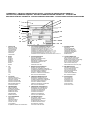
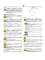
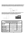
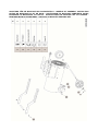
TYPENSCHILD – PRODUCT IDENTIFICATION PLATE – PLAQUETTE IDENTIFICATION PRODUIT –
- ETICHETTA IDENTIFICAZIONE PRODOTTO – ETIQUETA DE
IDENTIFICACIÓN DEL PRODUCTO –PRODUCTIDENTIFICATIELABEL - ETYKIETA IDENTYFIKACYJNA WYROBU
1 HERSTELLER
MANUFACTURER
CONSTRUCTEUR
COSTRUTTORE
FABRICANTE
FABRIKANT
PRODUCENT
2 MODEL
MODEL
MODÈLE
MODELO
MODELLO
MODEL
MODEL
3 TYP
TYPE
TYPE
TIPO
TIPO
TYPE
TYP
4 SCHUTZART
PROTECTION LEVEL
INDICE DE PROTECTION
GRADO DI PROTEZIONE
GRADO DE PROTECCIÓN
BESCHERMINGSGRAAD
STOPIE OCHRONY
5 SERIENNUMMER
SERIAL NUMBER
NUMÉRO DE SÉRIE
NUMERO DI SERIE
NÚMERO DE SERIE
SERIENUMMER
NUMER SERYJNY
6 LUFTFÖRDERMENGE
AIR OUTPUT
DÉBIT D'AIR
PORTATA DI ARIA
CAUDAL DE AIRE
LUCHTDEBIET
NATENIE PRZEPŁYWU POWIETRZA
7 LUFTAUSTRITTSTEMPERATUR BEI 20°C / 1,5 m
AIR OUTFLOW TEMPERATURE @ 20°C / 1,5 m
TEMPÉRATURE SORTIE AIR À 20°C /1,5 m
TEMPERATURA USCITA ARIA @ 20°C / 1,5 m
@ 20°C / 1,5 m
TEMPERATURA DE SALIDA DE AIRE a 20 °C / 1,5 m
UITGANGSTEMPERATUUR LUCHT @ 20°C / 1,5 m
TEMPERATURA POWIETRZA NA WYLOCIE PRZY 20°C/1,5 m
8 VERSORGUNGSDRUCK
SUPPLY PRESSURE
PRESSION D'ALIMENTATION
PRESSIONE DI ALIMENTAZIONE
PRESIÓN DE ALIMENTACIÓN
VOEDINGSDRUK
CINIENIE ZASILANIA
9 WÄRMELEISTUNG BEWERTET
NOMINAL HEATING OUTPUT
PUISSANCE THERMIQUE NOMINALE
POTENZA TERMICA NOMINALE
POTENCIA TÉRMICA NOMINAL
NOMINAAL THERMISCH VERMOGEN:
MOC CIEPLNA ZNAMIONOWA
10 GEMESSENE WÄRMELEISTUNG
MEASURED HEATING OUTPUT
PUISSANCE THERMIQUE MESURE
POTENZA TERMICA MISURATA
POTENCIA TÉRMICA MEDIDO
GEMETEN THERMISCH VERMOGEN
MOC CIEPLNA ZMIERZONA
11 GEMESSENEN GASVERBRAUCH
MEASURED GAS CONSUMPTION
CONSOMMATION GAZ MESURE
CONSUMO GAS MISURATO
CONSUMO GAS MEDIDO
GEMETEN GASVERBRUIK
ZUYCIE GAZU ZMIERZONA
12 STROMVERSORGUNG
ELECTRICAL SUPPLY
ALIMENTATION ÉLECTRIQUE
ALIMENTAZIONE ELETTRICA
ALIMENTACIÓN ELÉCTRICA
ELEKTRISCHE VOEDING
ZASILANIE ELEKTRYCZNE
13 STROMAUFNAHME
AMPERAGE
COURANT ABSORBÉ
CORRENTE ASSORBITA
CORRIENTE ABSORBIDA
STROOMVERBRUIK
POBÓR PRDU
14 CE-PRÜFNUMMER (PIN)
CERTIFICATION INITIALS (PIN)
SIGLE CERTIFICATION (PIN)
(-)
SIGLA CERTIFICAZIONE (PIN)
SIGLA CERTIFICACIÓN (PIN)
CERTIFICATIECODE (PIN)
OZNACZENIE CERTYFIKACJI (PIN)
15 BESTIMMUNGSLAND
COUNTRY OF DESTINATION
PAYS DE DESTINATION
PAESE DI DESTINAZIONE
PAÍS DE DESTINO
LAND VAN BESTEMMING
KRAJ PRZEZNACZENIA
16 GASKATEGORIE
GAS CATEGORY
CATÉGORIE GAZ
CATEGORIA GAS
CATEGORÍA GAS
GASCATEGORIE
KATEGORIA GAZU
11
1 3
2
5
15
8
9
10
12
16
4
7
13
6
14

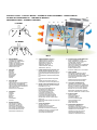
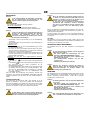
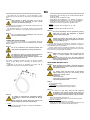
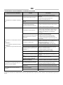
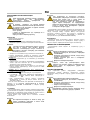
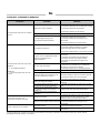
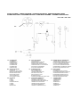
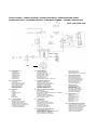
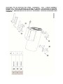
KONTROLLTAFEL - CONTROL BOARD - SCHÉMA DE FONCTIONNEMENT -
SCHEMA DI FUNZIONAMENTO - TABLERO DE MANDOS
WERKINGSSCHEMA - SCHEMAT DZIAŁANIA
Bild. 1
1 BRENNKAMMER
COMBUSTION CHAMBER
CHAMBRE DE COMBUSTION
CAMERA DI COMBUSTIONE
CAMARA DE COMBUSTION
VERBRANDINGSKAMER
KOMORA SPALANIA
2 BRENNER
BURNER
BRULEUR
BRUCIATORE
QUEMADOR
BRANDER
PALNIK
3 KÜHLGEBLÄSE
COOLING FAN
VENTILATEUR REFROIDISSEMENT
VENTILATORE RAFFREDDAMENTO
VENTILADOR DE REFRIGERACION
KOELVENTILATOR
WENTYLATOR CHŁODZCY
4 HANDGRIFF
HANDLE
POIGNEE
MANIGLIA
MANIJA
HANDGREEP
UCHWYT
5 ZÜNDELEKTRODE
IGNITION ELECTRODE
ELECTRODE ALLUMAGE
ELETTRODO ACCENSIONE
ELECTRODO DE ENCENDIDO
ONTSTEKINGSELEKTRODE
ELEKTRODA ZAPŁONOWA
6 THERMOELEMENT (Modell P)
THERMOCOUPLE (P model)
THERMOCOUPLE (Modèle P)
( P)
TERMOCOPPIA (Modello P)
TERMOPAR (Modelo P)
THERMOKOPPEL (Model P)
TERMOPARA (Model P)
7 IONISATIONSELEKTRODE (Modell PX)
IONISATION ELECTRODE (PX model)
ELECTRODE D'IONISATION (Modèle PX)
(
PX)
ELETTRODO DI IONIZZAZIONE (Modello
PX)
ELECTRODO DE IONIZACION (Modelo
PX)
IONISATIE-ELEKTRODE (Model PX)
ELEKTRODA JONIZACYJNA (Model PX)
8 RESET-TASTE ELEKTRONIK (Mod. PX)
RESET BUTTON OF THE ELECTRONIC
EQUIPMENT (PX mod.)
BOUTON DE REARMEMENT DE
L'APPAREILLAGE (Mod. PX)
( PX)
PULSANTE DI RIARMO DELL’
APPARECCHIATURA (Mod. PX)
PULSADOR RESTABLECIMIENTO
EQUIPO ELECTRÓNICO (Mod.PX)
RESETKNOP VAN DE APPARATUUR
(Model PX)
PRZYCISK RESETOWANIA APARATURY
(Model PX)
9 SCHALTER HEIZUNG
HEATING SWITCH
INTERRUPTEUR CHAUFFAGE
INTERRUTTORE RISCALDAMENTO
INTERRUPTOR DE LA CALEFACCIÓN
SCHAKELAAR VERWARMING
WYŁCZNIK OGRZEWANIA
10 STECKBUCHSE RAUMTHERMOSTAT
ROOM THERMOSTAT PLUG
PRISE THERMOSTAT D’AMBIANCE
PRESA PER TERMOSTATO AMBIENTE
ENCHUFE TERMOSTATO AMBIENTE
STOPCONTACT VOOR
KAMERTHERMOSTAAT
GNIAZDO TERMOSTATU OTOCZENIA
11 PIEZO-ZÜNDER
ENCENDEDOR PIEZOELÉCTRICO
ALLUMEUR PIEZO-ELECTRIQUE
ACCENDITORE PIEZOELETTRICO
PIEZO IGNITER
PIEZOELEKTRISCHE ONTSTEKER
ZAPALNIK PIEZOELEKTRYCZNY
12 TASTE DES THERMOVENTILS
THERMAL GAS VALVE BUTTON
BOUTON SOUPAPE GAZ THERMIQUE
PULSANTE VALVOLA GAS TERMICA
BOTÓN VÁLVULA DE GAS TÉRMICA
DRUKKNOP THERMISCHE GASKLEP
PRZYCISK TERMICZNY ZAWORU GAZU
13 ELEKTRO KABEL
POWER CORD
CABLE ELECTRIQUE
CAVO DI ALIMENTAZIONE
CABLE ALIMENTACION
VOEDINGSKABEL
KABEL ZASILANIA
14 SICHERHEITSTHERMOSTAT
OVERHEAT THERMOSTAT
THERMOSTAT DE SURCHAUFFE
TERMOSTATO DI SICUREZZA
TERMOSTATO DE SEGURIDAD
VEILIGHEIDSTHERMOSTAAT
TERMOSTAT ZABEZPIECZAJC
P MODEL 2
5
6
73
4
PX MODEL
1
9
13
12
9 8 10 13
11
14

DE
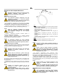
WICHTIG
Vor Benutzung des Gasheizers ist die Bedienungsanleitung durchzulesen. Die Benutzungsanweisungen sind streng zu
beachten. Der Hersteller haftet nicht für Sach- und Personenschäden infolge unsachgemäßen Gebrauchs des Gerätes.
Diese Betriebsanleitung ist fester Bestandteil des Gerätes. Sie ist daher sorgfältig aufzubewahren und muss das Gerät im
Fall eines Eigentumswechsels begleiten.
BESCHREIBUNG
Die Gasheizer sind zum Beheizen von gut belüfteten Räumen,
gemäß der DIN EN 1596:2005: Ortsveränderliche und tragbare
Warmlufterzeuger nicht für den Hausgebrauch bestimmt.
Achtung
NICHT ZUM BEHEIZEN DER WOHNBEREICHE IN
WOHNGEBÄUDEN VERWENDEN.
FÜR DIE VERWENDUNG IN ÖFFENTLICHEN GE-
BÄUDEN GELTEN DIE NATIONALEN BESTIMMUNGEN.
Die Gasheizer können mit Propan (G31) oder einem
Flüssiggasgemisch aus Butan (G30) und Propan (G31) gemäß den
verschiedenen Gaskategorien betrieben werden, die in Tab. I und auf
dem Typenschild des Geräts angegeben sind.
Die Gasheizer sind Direktheizgeräte mit erzwungener Konvektion.
Die Luft wird unter Ausnutzung der während der Verbrennung
erzeugten Wärmeenergie erhitzt und anschließend, gemeinsam mit
den Verbrennungsgasen, in den zu beheizenden Raum geleitet. Der
Raum muss stets belüftet sein, um einen ausreichenden
Luftaustausch zu gewährleisten.
Zum Schutz im Falle schwerwiegender Fehlfunktionen sind
verschiedene Sicherheitsvorrichtungen vorgesehen:
• Das Sicherheitsthermoelement sowie das Thermoventil sprechen
an, wenn die Flamme instabil ist oder erlischt. Die Gaszufuhr wird
unterbrochen.
• Die Steuerelektronik des Brenners (Modelle PX) unterbricht den
Betrieb, wenn die Flamme unregelmäßig ist oder erlischt (die rote
Lampe der Taste leuchtet dann ständig).
• Der Sicherheitsthermostat LI spricht an, wenn die Brenn-
kammertemperatur den Sicherheitsgrenzwert überschreitet.
Die Auslösung von einer der Sicherheitseinrichtungen bewirkt die
dauerhafte Außerbetriebnahme oder die “Blockierung” des Gas-
heizers.
Achtung
Man muss stets zuerst die Ursache der "Blockierung"
suchen und beseitigen, bevor man den Gasheizer
wieder startet (siehe "STÖRUNGEN, URSACHEN UND
ABHILFEN").
Der Start kann bei den Modellen PX erst wiederholt
werden, nachdem die Reset-Taste (8) gedrückt wurde
(das rote Licht erlischt dann).
Achtung
Die Lampe der Taste (8) der Elektronik (Modelle PX)
kann auf unterschiedliche Weise leuchten:
• Ausgeschaltet: ordnungemäßer Betrieb des Geräts;
• Schnelles Blinken: das Gerät führt den Startzyklus
aus;
• Langsames Blinken: das Gerät befindet sich im
Pausen- oder Bereitschaftszustand in Erwartung der
Anforderung des Heizbetriebs;
• Ständig eingeschaltet: das Gerät befindet sich im
Zustand “Blockierung”.
ALLGEMEINE HINWEISE
Die Installation, die Einstellung und die Benutzung des Gasheizers
müssen den geltenden nationalen und örtlichen Vorschriften und
Gesetzen in Hinsicht auf den Gebrauch des Gerätes entsprechen.
Der Sicherheitsabstand von Wänden, Fußboden und Decke soll
mindestens 2 m betragen.
Achtung
Das Gerät darf für seinen Betrieb nicht auf Böden auf-
gestellt werden, die aus brennbaren Materialien
bestehen.
Achtung
Der Betrieb in Kellerräumen und unter Erdgleiche sind
wegen einer möglichen Ansammlung des Propan-
und/oder Butangases gefährlich.
Es ist Folgendes sicherzustellen:
• Die Anweisungen der vorliegenden Anleitung sind streng zu
beachten;
• Der Gasheizer darf nicht in feuer- oder explosionsgefährdeten
Bereichen aufgestellt werden;
• In Gerätenähe keine feuergefährlichen Materialien aufbewahren
(Abstand mindestens 3 m);
• Etwaige Wände und Decken aus entflammbarem Material
dürfen sich nicht zu stark erhitzen;
• Es sind die notwendigen Brandschutzmaßnahmen zu ergreifen;
• Die Belüftung des Aufstellungsraumes des Gasheizers muss
stets gewährleistet sein und dem Bedarf des Brenners
entsprechen; insbesondere sind die Grenzwerte für die
Luftqualität in dem zu beheizenden Raum gemäß der nationalen
oder lokalen Vorschriften oder, in Ermangelung dieser, gemäß
EN 1596:2008 zu beachten:
• Das Mindestvolumen des Raums muss mit einem Verhältnis
Wärmeleistung/Volumen von 100 W/m3 bestimmt werden. Das
Raumvolumen darf keinesfalls weniger als 100 m3 betragen.;
• Es muss eine Lüftungsöffnung mit einer Fläche von mindestens
25 cm2 pro kW Wärmeleistung garantiert sein, wobei die
Mindestfläche von 250 cm2 zu gleichen Teilen zwischen oben
und unten aufgeteilt sein muss.
• Die Luftansaug- bzw. Luftförderkanäle dürfen nicht verdeckt oder
verstellt werden z.B. durch abgelegte Planen oder Abdeckungen
auf dem Gerät oder Wände oder Gegenstände;
• Der Gasheizer soll in der Nähe einer Schaltanlage aufgestellt
werden, deren Stromwerte den deklarierten Anschlusswerten
entsprechen;
• Für das Gerät soll ein fester Aufstellungsplatz vorgesehen sein;
• Den Warmluftstrahl nicht auf die Gasflasche richten;
• Das Gerät soll während des Betriebs regelmäßig überwacht und
vor der Inbetriebsetzung kontrolliert werden;
• Bei Beginn jedes Gebrauchs ist vor Anschluss des Netzsteckers
zu überprüfen, dass der Ventilator ungehindert dreht;
• Nach jedem Gebrauch den Trennschalter ausschalten, das
Netzkabel aus der Steckdose ziehen, den Gasabsperrhahn
schließen und den Gasschlauch lösen und dicht verschließen.
Achtung
Dieses Gerät darf nicht von Personen (einschließlich
Kindern) mit verminderten physischen, sensorischen
und geistigen Fähigkeiten oder mit unzureichender
Erfahrung und Kenntnis benutzt werden, sofern sie
nicht über den Gebrauch des Gerätes von der
aufsichtspflichtigen Person eingewiesen und belehrt
wurden.

DE
INSTALLATION
Achtung
Alle in diesem Abschnitt aufgeführten Arbeiten dürfen
nur vom Fachmann ausgeführt werden.
Die Technischen Regeln für Flüssiggas (TRF) 2012
sowie die Unfallverhütungsvorschriften (UVV, BGV
D34) sind zu beachten.
ELEKTRISCHE ANSCHLÜSSE
Achtung
Die Stromversorgungsleitung des Gasheizers muss
mit einer Erdung und einem FI-Schutzschalter
versehen sein.
Der Netzstecker ist an eine Schaltanlage mit
Trennschalter anzuschließen.
Bevor man den Gasheizer an das Stromnetz anschließt, muss man
sicherstellen, dass die Eigenschaften des Stromnetzes mit den
Angaben auf dem Typenschild übereinstimmen.
Die Modelle PX können über die Steckbuchse (10) an einen
Raumthermostat oder an eine andere Zubehöreinrichtung (z.B. einen
Zeitschalter) der Anlage angeschlossen werden.
Achtung
Die INBETRIEBNAHME oder Ausschaltung des
Gasheizers darf niemals durch den Anschluss des
Raumluftthermostats (oder anderer
Kontrollvorrichtungen) an die Netzleitung geschaltet
werden.
Die Installation und der Anschluss des Raumthermostaten werden in
der beigefügten speziellen Anleitung beschrieben.
In dem in der vorliegenden Anleitung enthaltenen elektrischen
Schaltplan ist nur der elektrische Anschluss des Zubehörs an die
vorhandene elektrische Anlage des Gasheizers angegeben.
Achtung
Es ist verboten, den Gasheizer an ein Luftkanalsystem
anzuschließen: Andernfalls besteht hohe Brandgefahr!
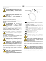
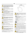
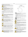
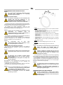
ANSCHLUSS AN DIE GASFLASCHE
Der Gasheizer kann an eine Gasflasche mit geeigneter Größe
angeschlossen werden, wobei eine Schlauchbruchsicherung (b)
zwischen Gasflasch und Gasheizer zu installieren ist.
Achtung
Alle Anschlüsse haben ein linksgängiges Gewinde und
müssen daher entgegen dem Uhrzeigersinn ange-
zogen werden.
Achtung
Die Abmessungen der Gasflasche oder müssen in
Abhängigkeit vom verlangten Gasvolumenstrom und
dem Versorgungsdruck festgelegt werden.
Der Versorgungsdruck am Druckregler muss stets
mehr als 2 bar betragen.
Der Gasheizer wird komplett mit Gasschlauch (a) und Druckminderer
(c) mit Fittings (d) für den Anschluss an verschiedenartige Gas-
flaschen geliefert.
Je nach Bestimmungsland kann der Gasheizer mit verschiedenen
Typen von Gasdruckreglern geliefert werden.
Achtung
Es liegt in der Verantwortung des Installateurs, sicher-
zustellen, dass das richtige Fitting für den Anschluss
der Gasflasche verwendet wird.
Stets zuerst das Fitting und erst dann den mit einem
Drehfitting versehenen Druckregler auf die Gasflasche
schrauben.
Typ I
• Druckregler mit Anschluss G5 für AT-BG-CY-DK-DE-EE-LT-LV-
MK-MT-RO-TR.
• Fitting G5/G2, mit Anschluss G2 für BE-CZ-ES-FR-HR-HU-LU-
PL-PT-SI-SK. (nur auf Anfrage)
• Fitting G5/G1, mit Anschluss G1 für IT-GR
• Anschluss G5/G7, mit Anschluss G7 für FI - IE - GB (nur auf
Anfrage)
• Anschluss G5/G9, mit Anschluss G9 für SE - NO (nur auf
Anfrage)
• Anschluss G5/G5R, mit Anschluss G5R für CH - NL (nur auf
Anfrage)
• Dichtung für NL, die in NL obligatorisch am Druckregler vom
Typ G5 anzubringen ist. (nur auf Anfrage)
Typ II
• Druckregler mit Anschluss G7 für FI - IE - GB.
Typ III
• Druckregler mit Anschluss G9 für SE - NO
Achtung
Die Dichtigkeit der Fittings muss mit Seifenwasser
geprüft werden: Sind Luftblasen zu sehen, tritt Gas
aus.
Achtung
Propan und Butan sind Gase, die schwerer als Luft
sind, und sich daher im Fall eines Lecks am Boden
des Installationsraums oder der darunter liegenden
Räume ansammeln können.
Die im Lieferumfang enthaltene Schlauchbruchsicherung (b) muss
zwingend installiert werden. Die Gasflasche muss im Freien, entfernt
von Wärmequellen und offenen Flammen, ausgewechselt werden.
Hierbei sind alle in diesem Abschnitt genannten Vorschriften zu
beachten.
Achtung
Stets sicherstellen, dass zwischen den Druckminderer
und der Gasflasche die Dichtungen eingesetzt sind,
falls beim jeweiligen Anschlusstyp welche vorgesehen
sind.
Beim Anschließen darauf achten, dass der Gas-schlauch nicht
verdreht wird. Der Gasschlauch kann durch
Torsionsbeanspruchung ernsthaften Schaden nehmen.
Anschluss 1/4 Zoll IG -
Anschluss 3/8 Zoll IG
1/4 Zoll IG

DE
BENUTZUNG
Achtung
Vor der Inbetriebnahme des Gasheizers sicherstellen,
dass die Eigenschaften des Stromnetzes mit den
Angaben auf dem Typenschild übereinstimmen.
INBETRIEBNAHME
Zum Starten des Gasheizers wie folgt verfahren:
BEI ALLEN MODELLEN
• Den Druckregler auf den maximalen Druck einstellen.
• Den Absperrhahn der Gasflasche langsam vollständig öffnen.
Achtung
Im Falle von Gaslecks sofort den Gasabsperrhahn und
den Hahn der Gasflasche schließen, den Gasheizer
ausschalten, den Netzstecker ziehen und den
technischen Kundendienst für die Suche, der Ursache
des Gasaustritts verständigen.
• Sicherstellen, dass sich der Schalter (9) in der Schaltstellung
“0” befindet.
• Den Gasheizer über den Trennschalter an der Schaltanlage mit
Strom versorgen;
MODELLE P und
• Den Schalter drücken, um ihn in die Schaltstellung (I) zu schal-
ten: Der Ventilator läuft an.
• Die Taste (12) des Thermoventils gedrückt halten und gleich-
zeitig die Taste des Piezozünders (11) einmal oder mehrmals
drücken, bis sich die Flamme entzündet hat.
• Die Taste (12) weitere 15 bis 20 Sekunden gedrückt halten, bis
sich das Thermoelement (6) erwärmt hat, und dann lösen: Die
Flamme bleibt eingeschaltet.
MODELLE PX (mit oder ohne angeschlossenem Raumluft-
thermostat)
• Verstellung von Schalter (9)
• in die Stellung wenn der Thermostat nicht angeschlossen
ist
• in die Stellung wenn der Thermostat angeschlossen ist und
den Thermostat auf eine höhere Temperatur als die
Raumtemperatur einstellen
• Zur Außerbetriebnahme des Gerätes ist im manuellen Betrieb
der Schalter (9) in die Position „0“ zu schalten (Modelle P, oder
PX) bzw. der Raumluftthermostat zu betätigen (nur Modelle
PX). Die Flamme erlischt und der Gebläsemotor wird
unverzüglich gestoppt.
Falls das Gerät nach Ausführung der genannten Schritte nicht
funktioniert, den Abschnitt „STÖRUNGEN, URSACHEN UND AB-
HILFEN” durchlesen und den Grund für den Funktionsausfall er-
mitteln.
AUßERBETRIEBNAHME
Zum Abschalten des Geräts den EIN / AUS Schalter (9) in die
Position „0“ (Modelle P, oder PX) zu schalten bzw. der Raumluft-
thermostat zu betätigen (nur Modelle PX): Die Flamme erlischt dann
und der Ventilatormotor schaltet sich aus. Danach ist der Gasab-
sperrhahn zu schließen und der Trennschalter auszuschalten.
Achtung
Bei dem Modell P muß vor dem erneuten Starten des
Gasheizers mindestens 2 Minuten abgewartet werden,
damit das Thermoelement vollständig abgekühlt.
Achtung
Wenn der Gasheizer nicht ständig gebraucht wird, ist
es ratsam, vor dem Ausschalten jedes Mal zuerst den
Gashahn zu schließen und dann den Schalter (9) zu
drücken oder den Thermostaten zu betätigen.
So wird auch das im Gasschlauch des Gasheizers
verbliebende Gas verbraucht, wodurch vermieden
wird, dass es anschließend langsam entweicht bzw.
plötzlich entweicht, wenn der Gasschlauch gelöst
wird.
Bei den PX Modellen ist die Nachbelüftungsfunktion nach dem Aus-
schalten aktiviert. Der Ventilator läuft 30 Sekunden lang weiter, um
die Brennkammer abzukühlen.
Ist diese Funktion nicht gewünscht, ist der PVC-Steckverbinder (in
der Serienausstattung enthalten und in die Schaltanlage eingesetzt)
zu entfernen.
LÜFTUNG
Die Modelle P sind auch als einfache Lüfter nutzbar: Hierzu ist die
Gasleitung nicht anzuschließen und das Gerät durch Betätigung des
Schalters (9) in der Stellung (I) zu starten.
TRANSPORT UND HANDHABUNG
Der Gasheizer kann mit dem Griff angehoben und transportiert
werden.
Achtung
Vor dem Ortswechsel des Gerätes sind die folgenden
Maßnahmen zu ergreifen:
• Das Gerät gemäß den Anweisungen aus dem
Abschnitt „AUßERBETRIEBNAHME“ stoppen;
• Die elektrische Versorgung durch Abziehen des
Netzsteckers abschalten;
• Den Gasabsperrhahn schließen und den Gas-
schlauch lösen;
• Abkühlung des Gasheizers abwarten.
Achtung
Während des Transports und/oder der Ablage ist
darauf zu achten, dass die Gasventileinheit und die
Gasanschlussleitungen vor etwaigen Stößen und
Beschädigungen geschützt sind.
WARTUNG
Zur Gewährleistung des regelmäßigen Betriebs des Geräts müssen
der Ventilatormotor, das Ansauggitter, die Brennkammer und der
Brenner regelmäßig gereinigt werden, wobei alle eventuellen
Fremdkörper zu entfernen sind.
Achtung
Vor Wartungsarbeiten sind die folgenden Maßnahmen
zu ergreifen:
• Das Gerät gemäß den Anweisungen aus dem
Abschnitt „AUßERBETRIEBNAHME“ stoppen;
• Die elektrische Versorgung durch Abziehen des
Netzsteckers abschalten;
• Den Gasabsperrhahn schließen;
• Abkühlung des Gasheizers abwarten.
Achtung
Eine unsachgemäße Reinigung des Gasheizers kann
Sach- und/oder Personenschäden zur Folge haben.

DE
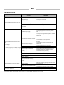
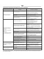
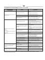
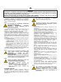
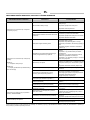
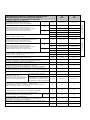
STÖRUNGEN, URSACHEN UND ABHILFEN
STÖRUNG
URSACHEN ABHILFEN
• Stromwerte des Anschlussnetzes überprüfen
• Elektrische Anschlüsse überprüfen
• Keine elektrische Versorgung
• Richtige Stellung auswählen
• Falsche Stellung des Hauptschalters • Richtige Stellung auswählen
• Elektrische Anschlüsse überprüfen
• Den Stromanschluss des Thermostaten
kontrollieren.
• Der Gasheizer startet nicht und der Ventilator
läuft nicht an.
• Nicht ordnungsgemäßer Betrieb des
Raumluftthermostats (Modell PX)
• Funktionsfähigkeit des Thermostats überprüfen
• Die Gasflasche kontrollieren.
• Den Gasschlauch kontrollieren und von eventuellen
Verunreinigungen säubern, die den Gasfluss
behindern.
• Ungenügende Gaszufuhr.
• Den Druckregler kontrollieren und ggf.
auswechseln.
• Kontrollieren, dass die Ansaug- und die
Ausströmgitter nicht versperrt sind
• Kontrollieren, dass der Raum ausreichend belüftet
ist
• Kontrollieren, dass die Warmluft ungehindert
austreten kann
• Flammensensor herausnehmen und
reinigen
• Kontrollieren, dass der Gasförderstrom oder –druck
nicht zu hoch sind
• Den Zünder (piezoelektrisch bei den Modellen P;
elektronisch bei den Modellen PX) und den
Stromanschluss kontrollieren; den Zünder ggf.
auswechseln.
• Die Flamme zündet nicht.
• Die Position der Zündelektrode kontrollieren.
• Sicherheitsthermostat defekt. • Thermostat kontrollieren und ggf. auswechseln
• Den Einschaltvorgang wiederholen und die Taste
des Thermoventils mindestens 30 Sekunden
gedrückt halten.
• Die Position des Thermoelements kontrollieren.
• Das Thermoelement erwärmt sich nicht
und das Thermoventil schließt sich
(Modell P - )
• Das Thermoelement herausnehmen und reinigen.
• Thermoelement defekt (Modell P - )
• Das Thermoelement kontrollieren und ggf.
auswechseln.
• Die Ionisationselektrode erkennt die
Flamme nicht (Modell PX).
• Den Flammensensor herausnehmen und reinigen
bzw. auswechseln.
• Auslösung der Kontrollvorrichtung für den
einwandfreien Brennerbetrieb
(Modell PX)
• Den Technischen Kundendienst kontaktieren
• Der Gasheizer startet nicht und schaltet ab,
während:
MODELL P-
>> der Ventilator weiter läuft.
MODELL PX
>> die Lampe (8) ständig rot leuchtet.
• Elektronische Kontrollvorrichtung defekt
(Modell PX)
• Vorrichtung kontrollieren und ggf. auswechseln
• Die Magnetventile schließen sich nicht,
weil sie durch Fremdkörper oder
Verunreinigungen blockiert sind.
• Die Gaszufuhr unterbrechen und das im Schlauch
verbliebene Gas durch den Gasheizer verbrennen
lassen. Dann den Technischen Kundendienst
kontaktieren.
• Thermostat kontrollieren und ggf. auswechseln
• Der Gasheizer schaltet nach Ausführung des
Verfahrens für die "AUßERBETRIEBNAHME"
nicht ab.
• Raumthermostat defekt (Modell PX) • Den Stromanschluss des Thermostaten
kontrollieren.
• Fremdkörperablagerungen an den
Ventilatorflügeln
• Fremdkörper entfernen
• Starkes Betriebsgeräusch oder Vibrationen
des Gebläses • Schwache Luftzirkulation
• Mögliche Behinderungen des Luftdurchgangs
beseitigen
Wenn die Fehlerursache mit den beschriebenen Kontrollen und Abhilfemaßnahmen nicht behoben werden konnte, wenden Sie sich bitte an den
nächsten Händer oder an den Kundendienst.

EN
IMPORTANT
Before using the space heater, carefully read all of the instructions and follow them scrupulously. The manufacturer
cannot be held responsible for damage to persons and/or property caused by improper use of the equipment.
This instruction manual is an integral part of the equipment and must therefore be stored carefully and passed on with the
unit in the event of a change of ownership.
DESCRIPTION
Space heaters are designed for non-domestic heating of medium
and large ventilated premises, for which a mobile heating system is
required in accordance with EN 1596:2008.
Warning
DO NOT USE TO HEAT HABITABLE AREAS OF
RESIDENTIAL BUILDINGS.
REFER TO NATIONAL REGULATIONS FOR USE IN
PUBLIC BUILDINGS.
Space heaters can be run on propane gas (G31) or on L.P.G.
(butane G30 and propane G31) according to the different gas
categories indicated on Tab. I and shown on the heater identification
plate.
Space heaters are direct-combustion and forced convention units.
Air is heated by the thermal energy generated during combustion and
is then conveyed to the room to be heated along with the combustion
products: the room MUST be suitably ventilated to ensure adequate
air circulation.
Various safety devices trip in the event of serious malfunction:
• the thermocouple and the thermal gas valve (P and models) trip
to close the gas flow if the flame is irregular or if it goes out;
• the electronic burner control unit trips if the flame is irregular or
goes out (type PX models): the reset button (8) lights up with a
steady red light;
• the overheating thermostat LI trips when the temperature of the
combustion chamber exceeds the safety limit;
In each of the cases described above, the space heater stops
working in lock-out condition.
Warning
You must always identify the cause of the “block” and
eliminate it before restarting the heater (see:
“TROUBLESHOOTING”).
Type PX models can restart only if reset button “8” is
pressed (red lamp is off).
Warning
For PX models, the reset button (8) may have different
light types:
• light off: unit is working normally, flame is regular.
• fast flashing: unit is running on starting cycle.
• slow flashing: unit is in stand-by status, waiting for
heating request.
• steady light: lock-out status.
GENERAL ADVICE
The heater must be installed, set up and used in accordance with
the applicable regulations and laws relating to the use of such
equipment.
Minimum distance from surrounding walls and/or ceiling: 2 m.
Warning
Do not use the heater on floors made with flammable
materials.
Warning
Use in basements or below ground level is hazardous
because of gas stagnation.
Make sure that:
• The instructions in this manual are carefully followed;
• The heater is not installed in an area where there is a high risk
of fire or explosions;
• No flammable materials are stored in the vicinity of the heater
(minimum distance: 3 m);
• There is no overheating of walls, or ceilings made of flammable
materials,
• All precautions have been taken to prevent fires;
• The premises in which the heater is installed are sufficiently
ventilated for the burner requirements; in particular, limits
regarding air quality in the room to be heated must conform to
applicable national or local laws or, in the absence of any
standards and/or indications, to the provisions of EN 1596:2008:
• minimum room volume must be measured with thermal
power/volume ratio equal to 100 W/m3. Room volume must
NEVER be less than 100 m3;
• a minimum ventilation area of 25 cm2 per kW of thermal
power must be provided, the minimum being 250 cm2, divided
equally between the upper and lower part;
• Nothing is obstructing the aspiration and expulsion of air;
movement of air may be obstructed in various ways including
placing covers or other objects on the heater or positioning the
heater too near a wall or other large object;
• The generator is placed near a power switchboard having
specifications that conform to those declared;
• The unit is placed in a stable position;
• The hot air jet is directed towards the cylinder.
• The heater is regularly monitored during operation and checked
before being started;
• At the beginning of each work period, a check is made that the
fan moves freely before plugging the heater into the electrical
power supply;
• At the end of each work period, the mains switch is disengaged
and supply power cord removed, main gas stopcock is closed
and gas tube disengaged and sealed.
Warning
This unit may not be used by persons (including
children) with reduced physical, sensorial or mental
capacities or with limited experience and familiarity
unless they are under supervision or instructed on
how to use the unit by the person responsible for its
safety.
INSTALLATION INSTRUCTIONS
Warning
All of the operations described in this section must be
performed by professional and skilled personnel only.
POWER CONNECTIONS
Warning
The power line must be earthed and fitted with a
residual current circuit breaker.
The power cable must be connected to a panel fitted
with a cut-out.
Before plugging the heater into the electrical power supply, check
that the power supply specifications are the same as those stated on
the identification plate.

EN
PX models may be connected to a room thermostat or other
accessories (such as the timer) by connecting to the thermostat plug
(10).
Warning
Never attempt to switch the heater on or off by
connecting the room thermostat (or other control
devices) to the electrical power line.
Installation and connection of room thermostat are described in the
specific instructions enclosed.
The electrical diagram in this manual shows only the electrical
connection of the accessory to the existing electrical system of the
heater.
Warning
Do not connect any air distribution hose: this will
cause a severe fire hazard!
CONNECTION TO GAS CYLINDER
The heater must be connected to an appropriately sized gas
cylinder. A gas supply stopcock must be installed between the heater
and the cylinder.
Warning
All of the connections have left-hand threads, and
must therefore be tightened by turning anticlockwise.
Warning
The dimensions of the gas cylinder must be based on
the required gas flow rate and supply pressure.
The supply pressure to the pressure regulator must
always be greater than 2 bar.
The heater is supplied complete with gas hose (a) and pressure
reducer (c) with fittings (d) for connection to different types of
cylinders.
Depending on the country of destination, the heater may be
supplied with various types of gas pressure regulator.
Warning
The installer is responsible for guaranteeing that the
correct fitting is used for the connection to the gas
cylinder.
Always tighten the cylinder fitting first, and then the
pressure regulator, which has a swivel fitting.
TYPE I
• pressure regulator with G5 fitting for AT-BG-CY-DK-DE-EE-LT-
LV-MK-MT-RO-TR-NL.
• G5/G2 fitting, with G2 fitting for G2 for BE-CZ-ES-FR-HR-HU-
LU-PL-PT-SI-SK.
• G5/G1 fitting, with G1 fitting for IT-GR
• G5/G7 fitting, with G7 fitting for FI - IE – GB (only if requested)
• G5/G5R fitting, with G5R fitting for CH – NL (only if requested)
• G5/G9 fitting, with G9 fitting for SE – NO (only if requested)
• seal for NL, to install on G5 pressure regulator for NL.
TYPE II
• pressure regulator with G7 fitting for FI - IE - GB.
TYPE III
• pressure regulator with G9 fitting for SE - NO.
Warning
The seal of the fittings must be checked by pouring
liquid soap on them: the appearance of bubbles
indicates a possible gas leak.
Warning
Propane and buthane are heavier than air, therefore
any gas leakage can cause gas stagnation on the floor
or in any underlying room.
A safety valve (b) may be ordered for protection in case of a
broken gas hose. Installation of this valve is mandatory if required by
local installation laws and regulations.
The gas cylinder must be changed and replaced in an open room,
away from sources of heat and open flame, taking care to check that
the instructions in this paragraph are followed.
Warning
Always make sure that the seal (if required by the
fitting) is present between the reducer and the
cylinder.
Make sure that the gas hose has been tightened
without being twisted: any stress from twisting can
seriously damage the hose.
OPERATING INSTRUCTIONS
Warning
Before switching on the heater, check that the power
supply specifications are the same as those stated on
the identification plate.
Warning
For models, check that the arrows on the voltage
supply selector key cover (11) are pointing to the
voltage value required, 230 V.
If necessary:
• remove the cover;
• press switch (11) to the position required;
• replace the protective cover.
START
To start the space heater:
ALL MODELS
• Set the pressure regulator to maximum pressure
• Slowly open the gas stopcockon the gas cylinder.
Warning
In case of a gas leak, close the gas stopcock
immediately, close the gas cylinder valve, switch off
the heater, remove the plug from the electrical panel,
and call customer service to find the origin of the leak.
• Make sure the switch (9) is set to “0”;
• Turn on the disconnecting switch on the main electrical panel;
P AND ALL MODELS
• Move the switch (9) to position (I): fan starts;
• Press the gas valve button (12) and simultaneously press the
piezoigniter (11) once or twice until the flame light up.

EN
• Keep pressed the gas valve button (12) for 15 / 20 seconds until
the thermocouple is sufficiently heated: when button 12 is
released, the flame stays on.
PX MODELS (with or without room thermostat connected)
• Move the switch (9):
• to position if room thermostat is not connected
• to position if room thermostat is connected and set it to a
temperature higher than room temperature
• Automatic starting cycle starts and light (8) flashes rapidly until
the flame lights up.
If the heater still does not function, see TROUBLESHOOTING” to
identify the cause of the malfunction.
STOP
To stop operation turn the switch (9) to position “0” if operation is
manual, or, for PX model, turn thermostat adjustment down: the
flame goes out and the fan motor stops.
Lastly, close the gas supply stopcock and turn off the isolation
switch.
Warning
For P model: wait at least 2 minutes before restarting
the heater, to allow the thermocouple to cool
completely.
Warning
If the heater is not used continuously, stop it by first
closing the gas supply stopcock and then switch it off
by pressing button (9) or by turning down the
thermostat:
this allows the gas in the gas tube to be fully used and
avoids any future leak when removing the gas tube.
For type PX model, a post-ventilation mode can be selected to
cool the combustion chamber for 30 seconds when the heater is
stopped. To select this function, insert the PVC connector (in the
electrical board) in the electronic control box (see WIRING
DIAGRAM).
VENTILATION
Type P models can be used as fans: simply disconnect gas tube
from gas bottle and turn the switch (9) to position (I).
TRANSPORTING AND HANDLING
The space heater can be lifted and moved by means of its handle.
Warning
Before moving the unit:
• Stop the heater as indicated in the “STOP”
paragraph;
• Disconnect the power supply by removing the plug
from the power socket;
• Close the gas stopcock and disconnect the gas
hose;
• Wait until the heater cools.
Warning
During transportation and/or storage, make sure the
gas valve group and gas connection pipes are not
knocked or damaged in any way.
MAINTENANCE
For efficient operation of the heater, clean the fan motor, suction
grill, combustion chamber, and burner at regular intervals. Remove
all debris.
Warning
Before doing any maintenance:
• Stop the heater as indicated in the “STOP”
paragraph;
• Disconnect the power supply by removing the plug
from the power socket;
• Close the gas supply stopcock;
• Wait until the heater cools.
Warning
Incorrect cleaning of the heater can cause damage to
property and/or people.

EN
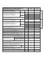
TROUBLESHOOTING
FAULTS
CAUSES REMEDIES
• Check power specifications
• Check power connections
• No power supply
• Check fuse
• Mains switch in wrong position • Select correct position
• Check thermostat position
• Check thermostat electrical connection
• The heater fails to start and fan does not
start
• Faulty operation of room thermostat
(PX model)
• Check thermostat operation
• Check if gas bottle is empty
• Check gas supply line and remove any debris
inside
•Insufficient gas supply
• Check pressure regulator and replace if necessary
• Check that the suction and the flow grills are
unobstructed
• Check that the room is well ventilated
• Check that hot air can escape freely
• Safety thermostat tripped due to
overheating of combustion chamber
• Check that gas flow and/or pressure are not
excessive
• Check that the suction and the flow grills are
unobstructed
• The flame does not light up
• Check ionization electrode positioniing
• Faulty safety thermostat • Check room thermostat and replace it if necessary
• Repeat starting operation keeping thermal gas
valve button pressed for at least 13 seconds
• Check thermocouple positioning
• Thermocouple is insufficiently
heated and gas valve closes (P -
models)
• Remove thermocouple and clean it
• Faulty thermocouple (P - models • Check thermocouple and replace it if necessary
• Ionization electrode does not detect
a flame (PX model)
• Remove flame sensor and clean or replace it
• Control unit tripped due to irregular
burner operation (PX model)
• Contact Customer Service
• The heater fails to start flame and stops
while:
P - MODEL
>> fan goes on
PX MODEL
>> lamp (8) lights up with steady red light
• Faulty electronic control unit (PX
model)
• Check the unit and replace it if necessary
• Gas solenoid valve does not close
because of debris
• Close main gas stopcock on gas bottle, let the
heater burn remaining gas in gas tube, and contact
Customer Service
• Check room thermostat and replace it if necessary
• The heater does not stop when "STOP"
procedure is followed
• Faulty room thermostat (PX model) • Check electric connection of room thermostat
• Foreign bodies on fan blades • Remove foreign bodies
• Fan noise or vibrations • Insufficienct air circulation • Eliminate all possible obstacles to proper air flow
If the heater is still not working properly, please contact your nearest dealer or authorized Service Centre.

FR
IMPORTANT
Avant toute utilisation du générateur, nous vous prions de lire attentivement toutes les instructions pour l'emploi
mentionnées ciaprès et d'en suivre scrupuleusement les indications. Le constructeur n'est pas responsable pour les
dommages aux personnes et/ou aux biens dus à une utilisation impropre de l'appareil.
Ce livret d'utilisation et d'entretien est partie intégrante de l'appareil. Il doit donc être conservé soigneusement et
accompagner l'appareil en cas de revente.
DESCRIPTION
Les générateurs d'air chaud sont destinés au chauffage non
domestique de locaux ventilés de moyennes-grandes dimensions,
lesquels requièrent un système de chauffage mobile et portatif, dans
le respect de la norme EN 1596:2008.
Attention
NE PAS UTILISER POUR LE CHAUFFAGE DE LOCAUX
D'HABITATION DE BATIMENTS RÉSIDENTIELS.
POUR L'UTILISATION DANS DES LOCAUX PUBLICS,
SE REPORTER AUX RÉGLEMENTATIONS
NATIONALES EN VIGUEUR.
Les générateurs d'air chaud peuvent fonctionner avec du gaz
propane (G31) ou avec un mélange GPL de gaz butane (G30) et de
gaz propane (G31), conformément aux catégories de gaz indiquées
dans le Tab. I et mentionnées sur la plaquette d'identification de la
machine.
Les générateurs d'air chaud sont du type à chauffage direct et
convection forcée. Les générateurs d'air chaud sont à combustion
indirecte. L'air est chauffé en utilisant l'énergie thermique
développée pendant la combustion puis envoyé au local à chauffer
avec les produits de la combustion sont éliminés à travers un conduit
de cheminée : le local devra toujours être correctement aéré afin
d'assurer un recyclage d'air suffisant.
Plusieurs dispositifs de sécurité interviennent en cas de
dysfonctionnement grave :
• le thermocouple de sécurité et la soupape gaz thermique
(modèles P et ) interviennent en coupant le débit de gaz
lorsque la flamme est instable ou s'éteint.
• l’équipement électronique de commande du brûleur (modèles
PX) intervient en arrêtant le fonctionnement lorsque la flamme
est irrégulière ou s'éteint (un témoin rouge fixe s'allume sur le
bouton (8)) ;
• le thermostat de température excessive LI intervient si la
température de la chambre de combustion franchit le seuil de
sécurité ;
L’intervention d'un des dispositifs de sécurité entraîne l'arrêt
permanent (ou “blocage”) du générateur d'air chaud.
Attention
Toujours identifier la cause à l'origine d'une situation
de “blocage” et l'éliminer avant de remettre le
générateur en marche (voir “ANOMALIES DE
FONCTIONNEMENT, CAUSES ET SOLUTIONS”).
Le démarrage des modèles PX ne peut être répété
sans avoir d'abord appuyé sur le bouton de
réarmement (8) (le témoin rouge fixe s'éteint).
Attention
Le témoin du bouton (8) de l'équipement électronique
(modèles PX) peut s'allumer de différentes manières :
• témoin éteint : l'appareil fonctionne correctement.
• clignotement rapide : le cycle de démarrage de la
machine est en cours.
• clignotement lent : éteint : l'appareil est en veille
(“stand-by”), en attendant une demande de
chauffage.
• lumière fixe : l'appareil est en état de “blocage”.
CONSEILS D'ORDRE GÉNÉRAL
L'installation, le réglage et l'utilisation du générateur d'air chaud
doivent être accomplis dans le respect de toutes les normes, lois
nationales et locales en vigueur concernant l'utilisation de la
machine.
La distance des parois environnantes, et/ou du plafond, doit être
au minimum de 2 mètre.
Attention
Il est interdit d'utiliser la machine sur un sol en
matériaux inflammables.
Attention
Il est dangereux d'utiliser le générateur dans des
locaux situés au sous-sol, à cause de la stagnation de
gaz propane et/ou butane.
Il convient de toujours s'assurer que :
• Les instructions du présent livret sont scrupuleusement
respectées ;
• Le générateur n'est pas installé dans des zones à fort risque
d'incendie ou d'explosion ;
• Aucun matériau inflammable n'est déposé à proximité de
l'appareil (la distance minimum doit être de 3 mètres) ;
• Tout risque de surchauffe des cloisons ou plafond réalisé dans
des matériaux inflammable a été analysé et écarté ;
• Toutes les mesures aptes à prévenir les incendies ont été
adoptées ;
• L'aération du local dans lequel est installé le générateur est
garantie et suffit aux besoins du brûleur ; en particulier les
limites relatives à la qualité de l'air du local à chauffer doivent
respecter les réglementations nationales ou locales en vigueur
ou, faute de normes et/ou indications, les termes de la norme
EN 1596:2008 ;
• Le volume minimum du local à chauffer doit être déterminé
selon un rapport puissance thermique / volume égal à 100
W/m3. Le volume du local à chauffer ne doit en aucun cas
être inférieur à 100 m3.;
• une aération minimum avec l'extérieur de 25 cm2 par kW de
puissance thermique doit être garantie, avec un minimum de
250 cm2, correctement réparti entre partie haute et partie
basse.
• Il n’y ait pas d’obstacles ou d’obstructions à l’aspiration et à la
sortie de l’air, tels que des toiles ou des couvertures étendues
sur l’appareil ou sur les parois, ou des objets encombrants à
côté du générateur ;
• Le générateur est installé à proximité d'un coffret électrique
d'alimentation possédant des caractéristiques conformes à
celles déclarées ;
• Une position fixe a été prévue pour l'appareil ;
• Le jet d'air chaud ne soit pas orienté vers la bouteille.
• Le générateur est régulièrement surveillé pendant son
fonctionnement et contrôlé avant sa mise en marche ;
• Au début de chaque période de fonctionnement, aucun
obstacle n'entrave la rotation du ventilateur avant de brancher
la fiche dans la prise du réseau ;
• A la fin de chaque utilisation, l'interrupteur électrique général
est exclu, le câble d'alimentation électrique est débranché, la
vanne d'arrêt de gaz est fermée et le tuyau de gaz est
débranché et scellé.

FR
Attention
Cet appareil ne doit pas être utilisé par des personnes
ou des enfants présentant un handicap physique,
sensoriel, mental ou ne possédant pas l'expérience et
les connaissances suffisantes à moins qu'ils aient été
formés sur son fonctionnement par une personne
responsable de la sécurité.
INSTRUCTIONS D'INSTALLATION
Attention
Toutes les instructions fournies dans ce paragraphe
ne doivent être exécutées que par un personnel
qualifié.
BRANCHEMENTS ÉLECTRIQUES
Attention
La ligne d'alimentation électrique doit être équipée
d'une mise à la terre et d'un disjoncteur
magnétothermique avec différentiel.
Le câble d'alimentation doit être branché à un coffret
électrique muni d'un sectionneur.
Avant de brancher le générateur au secteur, il est indispensable
de vérifier que les caractéristiques du réseau d'alimentation
électrique correspondent bien à celles reportées sur la plaquette
d'identification.
Les modèles PX peuvent être raccordés à un thermostat ambiant
ou à d'autres accessoires de l'installation (par exemple, l'horloge), en
utilisant la prise (10).
Attention
Ne jamais essayer de mettre en marche ou d'arrêter le
générateur en branchant le thermostat d'ambiance (ni
aucun autre dispositif de contrôle) sur la ligne
d'alimentation électrique.
Les procédures d'installation et de raccordement du thermostat
ambiant sont décrites dans les instructions spécifiques ci-jointes.
Le schéma électrique ci-contenu se rapporte exclusivement au
raccordement électrique de l'accessoire à l'installation électrique
existant du générateur d'air chaud.
Attention
Ne jamais brancher de système de canalisation de l'air
sur le générateur d'air chaud : cela peut entraîner un
grave risque d'incendie.
RACCORDEMENT À LA BOUTEILLE DE GAZ
Le générateur d'air chaud doit être raccordé à une bouteille de
gaz de dimensions appropriées, après interposition d'une vanne
d'arrêt de gaz.
Attention
Tous les raccords ont un filetage "gauche". Ils doivent
donc être vissés en tournant dans le sens contraire
des aiguilles d'une montre.
Attention
Les dimensions de la bouteille de gaz doivent être
déterminées avec précision, en fonction du débit de
gaz requis et de la pression d'alimentation.
La pression d'alimentation au manodétendeur doit
toujours être supérieure à 2 bars.
Le générateur d'air chaud est livré avec tuyau de gaz (a) et
manodétendeur (c) avec raccords (d) adaptés au raccordement de
bouteilles de différents types.
En fonction du pays de destination, le générateur d'air chaud peut
être fourni avec différents types de manodétendeurs.
Attention
L'installateur est tenu de vérifier que le raccord utilisé
est adapté au raccordement au type de bouteille de
gaz utilisé.
Visser toujours le raccord d'abord sur la bouteille et
ensuite seulement le manodétendeur muni d'un
raccord rotatif.
MODE I
• manodétendeur avec raccord de type G5 pour AT-BG-CY-DK-
DE-EE-LT-LV-MK-MT-RO-TR-NL.
• raccord G5/G2, avec fixation de type G2 pour BE-CZ-ES-FR-
HR-HU-LU-PL-PT-SI-SK.
• raccord G5/G1, avec fixation type G1 pour IT-GR
• raccord G5/G1, avec fixation type G7 pour FI - IE – GB (en
option seulement)
• raccord G5/G9, avec fixation type G9 pour SE - NO (en option
seulement)
• raccord G5/G5R, avec fixation type G5R pour CH - NL (en
option seulement)
• joint pour NL, à appliquer sur le manodétendeur du type G5
(obligatoire pour NL)
MODE II
• manodétendeur avec raccord de type G7 pour FI - IE - GB.
MODE III
• manodétendeur avec raccord de type G9 pour SE - NO.
Attention
L'étanchéité des jonctions doit être contrôlée en
appliquant du savon liquide : la présence éventuelle
de bulles est révélatrice d'une fuite de gaz.
Attention
Le propane et le butane étant plus lourds que l'air,
toute fuite entraîne une stagnation de gaz sur le sol du
local d'installation ou des locaux situés au-dessous.
Sur demande, il est possible de disposer de la sécurité stop-gaz
pour rupture du tuyau de gaz (b) ; cette sécurité doit obligatoirement
être installée si la réglementation ou la législation locale l'impose.
Le changement et le remplacement de la bouteille de gaz doivent
être effectués en plein air, loin de sources de chaleur et en l'absence
de flammes libres, en veillant à respecter les prescriptions
contenues dans ce paragraphe
Attention
Si le type de fixation le prévoit, toujours contrôler que
le joint est bien positionné entre le manodétendeur et
la bouteille.
S'assurer que le tuyau de gaz flexible soit serré sans
torsion : les torsions éventuelles peuvent
endommager fortement le tuyau de gaz.

FR
INSTRUCTIONS D'UTILISATION
Attention
Avant de mettre le générateur en marche, il est
indispensable de vérifier que les caractéristiques du
réseau électrique d'alimentation correspondent bien à
celles reportées sur la plaquette d'identification.
Attention
Sur les modèles , contrôler que les flèches sur le
couvercle du bouton (11) de sélection de la tension
d'alimentation soient en vis-à-vis de la valeur de
tension souhaitée, 110V o 230V.
Si nécessaire :
• retirer le couvercle ;
• enfoncer l’interrupteur (11) sur la position souhaitée;
• remonter le couvercle de protection.
MISE EN MARCHE
Pour mettre le générateur en marche :
POUR TOUS LES MODELES
• Régler le manodétendeur sur la pression maximale ;
• Ouvrir lentement et complètement la vanne d'arrêt de gaz de la
bouteille de gaz ;
Attention
En cas de fuite de gaz, fermer immédiatement la vanne
d'arrêt de gaz et le robinet de la bouteille de gaz.
Éteindre le générateur d'air chaud, débrancher la prise
au tableau électrique et contacter l'assistance
technique qui recherchera l'origine de la fuite de gaz.
• S'assurer que l'interrupteur (9) est sur la position “0” ;
• Alimenter l'appareil en agissant sur l'interrupteur général du
coffret électrique d'alimentation ;
MODELES P et
• Placer l'interrupteur dans la position (I) : le ventilateur
démarrera.
• Appuyer sur le bouton (12) de la soupape gaz thermique et
appuyer en même temps à plusieurs reprises sur l'allumeur
piézo-électrique (11), jusqu'à l'allumage de la flamme.
• Maintenir le bouton (12) enfoncé pendant au moins 15/20
secondes, jusqu'à réchauffer complètement le thermocouple
(6), puis le relâcher : la flamme demeurera allumée.
MODELES PX (avec ou sans thermostat ambiant raccordé)
• Placer l'interrupteur (9)
• sur la position si le thermostat n'est pas raccordé
• sur la position si le thermostat est raccordé et régler ce
dernier sur une température supérieure à la température
ambiante
• Le cycle de démarrage automatique de l'appareil est
automatiquement lancé et le bouton (8) clignote rapidement
jusqu'à l'allumage de la flamme.
Si après ces opérations le générateur ne fonctionne pas, il faut
consulter le paragraphe “ANOMALIES DE FONCTIONNEMENT,
CAUSES ET SOLUTIONS” et découvrir la cause qui empêche le
fonctionnement.
ARRÊT
Pour arrêter le fonctionnement de l'appareil, il est nécessaire
d'agir sur l'interrupteur (9), en le ramenant sur “0” (modèles P, ou
PX), ou sur le réglage du thermostat ambiant (modèles PX) : la
flamme s'éteindra et le moteur de ventilateur cessera
immédiatement de tourner.
Fermer la vanne d'arrêt du gaz et sectionner l'alimentation.
Attention
Pour les modèles P : avant de remettre le générateur
d'air chaud en marche, attendre pendant au moins 2
minutes pour permettre le refroidissement complet du
thermocouple.
Attention
Si le générateur est utilisée manière occasionnelle, il
convient de l'éteindre à chaque fois en refermant
d'abord la vanne d'arrêt de gaz puis en appuyant sur
l'interrupteur (9) ou en agissant sur le thermostat.
Cela permettra de consommer aussi le gaz résiduel
présent dans le tuyau d'alimentation du générateur, en
évitant sa lente dispersion ou une fuite inopinée en
cas de dépose ultérieure du tuyau de gaz.
Avec les modèles PX, il est possible de sélectionner la fonction
post-ventilation : lors de la mise hors tension : dans ce cas, le
ventilateur continue de fonctionner pendant 30 secondes, en
refroidissant la chambre de combustion. La sélection de cette
fonction s'effectue en branchant le connecteur PVC (livré de série et
intégré dans l'armoire électrique) sur la prise prévue sur la carte
électronique (voir SCHEMA ELECTRIQUE).
VENTILATION
Les modèles P peuvent être utilisés aussi comme de simples
ventilateurs : pour cela, il suffit de ne pas brancher le tuyau de gaz et
de mettre l'appareil en marche en appuyant sur l'interrupteur (9)
(position I).
TRANSPORT ET MANUTENTION
Le générateur d'air chaud peut être soulevé et transporté en
utilisant la poignée spécialement prévue à cet effet.
Attention
Avant de déplacer l’appareil il faut :
• Arrêter le générateur en suivant les indications du
paragraphe “ARRET”;
• Débrancher l’alimentation en enlevant la fiche de la
prise de courant;
• Fermer la vanne d'arrêt de gaz et débrancher le
tuyau de gaz ;
• Attendre que le générateur soit froid.
Attention
Au cours du transport et/ou du stockage, s'assurer
que le groupe soupape gaz et tuyau de liaison gaz ne
sont exposé à aucun risque de choc ou
d'endommagement.
MAINTENANCE
Pour garantir un fonctionnement optimal de l'appareil, il est
nécessaire de nettoyer régulièrement le moteur du ventilateur, la
grille d'aspiration, la chambre de combustion et le brûleur et de
retirer tout corps étranger éventuel.
Attention
Avant de commencer une quelconque opération
d’entretien il faut :
• Arrêter le générateur en suivant les indications du
paragraphe “ARRET”;
• Débrancher l’alimentation en enlevant la fiche de la
prise de courant;
• Fermer la vanne d'arrêt du gaz ;
• Attendre que le générateur soit froid.
Attention
Toute modalité impropre de nettoyage du
générateur peut causer des dommages aux biens e
t/ou aux personnes.

FR
ANOMALIES DE FONCTIONNEMENT, CAUSES ET SOLUTIONS
Si malgré les contrôles et les remèdes décrits la cause du dysfonctionnement n'a pas été trouvée, contacter le centre d'assistance agréé le plus
proche.
ANOMALIE DE FONCTIONNEMENT
CAUSES SOLUTIONS
• Vérifier les caractéristiques de l'alimentation
électrique
• Vérifier les branchements électriques
• Manque d'alimentation électrique
• Vérifier que le fusible est intact
• Mauvaise position de l'interrupteur
général
• Placer l'interrupteur sur la position correcte
• Vérifier la position du thermostat
• Vérifier le raccordement électrique du thermostat
• Le générateur et le ventilateur ne démarrent
pas.
• Fonctionnement irrégulier du
thermostat d'ambiance (modèle PX)
• Vérifier le fonctionnement du thermostat
• Vérifier la bouteille de gaz
• Vérifier la ligne d'alimentation en gaz et retirer les
éventuels résidus qui pourraient entraver le débit
• Alimentation en gaz insuffisante
• Vérifier le manodétendeur et le remplacer si
nécessaire
• Vérifier que les grilles de l’aspiration et de
l’évacuation ne sont pas obstruées
• Vérifier que le local est correctement aéré
• Contrôler que l'air chaud peut sortir librement
• Intervention du thermostat de sécurité
suite à surchauffe de la chambre de
combustion
• Contrôler que le débit ou la pression des gaz n'est
pas excessif
• Contrôler l'allumeur (piézo-électrique pour les
modèles P, électronique pour les modèles PX) et le
raccordement électrique, en procédant aux
remplacements nécessaires
• La flamme ne s'allume pas
• Contrôler la position de l'électrode d'allumage
• Thermostat de sécurité défectueux • Contrôler le thermostat et le remplacer si nécessaire
• Répéter l'opération de démarrage et maintenir le
bouton de la soupape de gaz thermique enfoncé
pendant au moins 30 secondes
• Contrôler la position du thermocouple
• Le thermocouple ne chauffe pas et la
soupape de gaz thermique se referme
(modèles P - )
• Déposer le thermocouple et le nettoyer
• Thermocouple défectueux (modèles P
- )
• Contrôler le thermocouple et le remplacer si
nécessaire
• L'électrode de ionisation ne détecte
pas la présence de la flamme (modèle
PX)
• Déposer le capteur de flamme et le nettoyer ou le
remplacer
• Intervention du système de
surveillance suite au fonctionnement
irrégulier du brûleur (modèle PX)
• Contacter l'Assistance technique.
• Le générateur ne s'arrête pas et s'arrête alors
que :
MODELES P-
>> le ventilateur continue de fonctionner
MODELE PX
>> le témoin rouge (8) s'allume de manière
fixe
• Système électronique de surveillance
défectueux (modèle PX)
• Contrôler le système et le remplacer si nécessaire
• Les électrovannes ne se referment
pas à cause d'éléments et/ou résidus
• Couper l'alimentation en gaz, laisser le générateur
brûler le gaz résiduel présent dans le tuyau et
s'adresser au Service d'Assistance Technique
• Contrôler le thermostat et le remplacer si nécessaire
• Le générateur ne s'arrête pas après avoir
effectué la procédure "ARRET" • Thermostat ambiant défectueux
(modèle PX) • Vérifier le raccordement électrique du thermostat
• Des corps étrangers se trouvent sur
les pales du ventilateur
• Retirer les corps étrangers
• Le ventilateur fait du bruit ou émet des
vibrations • La circulation d'air est insuffisante
• Supprimer tous les obstacles pouvant gêner le
passage de l'air

RU
,
, . -
/ , -
.
, , ,
.
,
EN 1596:2008.
Щ
Щ ,
.
Щ
.
(G31) (G30)
(G31)
, . I
.
.
, ,
, .
,
,
.
:
•
( P ) , ,
.
• ( )
, ,
( (8)
);
• LI ,
;
«»
.
,
, ,
(. «
: »).
(8) (
).
(8) ( )
:
• : .
• : .
• :
.
• : .
Щ
,
,
,
.
2 .
.
.
:
• , ,
;
•
;
•
( 3 );
• ,
, ;
• ;
• , ,
, ;
,
,
, –
EN 1596:2008:
•
/ =
100 /3.
100 3;
•
25 2
, 250 2,
.
•
/ , ., ,
,
, ;
• ,
;
• ;
• C
.
•
;
• ,
, ;
•
,
, ,
.

RU
, ,
( )
,
, ,
,
.
, ,
.
.
,
.
, ,
,
.
(., ),
(10).
,
(
) .
.
, ,
.
-
:
.
,
.
,
.
.
2
(a)
(c) (d)
.
.
,
.
, ,
.
I
• G5 AT-
BG-CY-DK-DE-EE-LT-LV-MK-MT-RO-TR-NL.
• G5/G2, G2 BE-CZ-ES-
FR-HR-HU-LU-PL-PT-SI-SK.
• G5/G1, G1 IT-GR
• G5/G7, G7 FI - IE – GB
( )
• G5/G9, G9 SE - NO (
)
• G5/G5R, G5R CH - NL
( )
• , NL,
G5, NL
II
• G7 FI - IE -
GB.
III
• G9 SE-NO
,
:
.
,
, ,
, .
(b);
,
.
, , ,
.
,
,
.
,
:
.

RU
,
,
.
,
,
, 110V 230V.
:
• ;
• (11),
;;
• .
:
•
•
,
,
.
• , (9) “0”;
•
, ;
P
• (9) (I):
.
• (12)
(11) .
• (12) 15 / 20
(6), :
.
PX (
)
• (9)
• ,
• , , ,
•
(8)
.
, . " ,
"
.
(9) «0» ( P, PX)
( ):
.
.
: 2
.
,
,
,
(9) .
,
;
,
.
-:
: 30
, .
, PVC (
)
(. ).
:
, (9) (I).
Щ
.
, :
• ,
"";
• ,
;
•
;
• .
, /
.
,
, ,
.
:
• ,
"";
• ,
;
• ;
• .
.

RU
:
,
.
•
•
•
•
•
•
•
•
•
•
( )
•
•
•
,
•
•
• ,
•
• ,
• -
• ,
• (
P, PX)
,
•
•
•
• ,
•
30
•
•
( P- )
•
• ( P- )
•
•
( )
•
• -
( )
•
•
, :
P-
>>
PX
>> (8)
•
( )
• ,
• -
• ,
• ,
•
•
( PX) •
•
•
•
•
•

IT
IMPORTANTE
Prima di usare il generatore, si prega di leggere con attenzione tutte le istruzioni d’uso riportate di seguito e di seguirne
scrupolosamente le indicazioni. Il costruttore non è responsabile per danni a cose e/o persone derivanti da uso improprio
dell’apparecchio.
Questo libretto di uso e manutenzione costituisce parte integrante dell’apparecchio e deve quindi essere conservato con
cura e accompagnare l’apparecchio in caso di passaggio di proprietà.
DESCRIZIONE
I generatori d’aria calda sono destinati al riscaldamento non
domestico di locali ventilati di medie o grandi dimensioni, per i quali
si richiede un sistema di riscaldamento mobile e portatile, in accordo
alla norma EN 1596:2008.
Attenzione
NON UTILIZZARE PER IL RISCALDAMENTO DELLE
AREE ABITABILI DI EDIFICI RESIDENZIALI.
PER L’USO IN EDIFICI PUBBLICI, FARE RIFERIMENTO
AI REGOLAMENTI NAZIONALI.
I generatori d’aria calda possono funzionare con gas propano
(G31) o miscela g.p.l. di gas butano (G30) e gas propano (G31)
secondo le diverse categorie gas che sono indicate in Tab. I e
riportati sulla targhetta di identificazione della macchina.
I generatori d’aria calda sono del tipo a riscaldamento diretto e
convezione forzata. L’aria è riscaldata utilizzando l’energia termica
sviluppata durante la combustione ed è in seguito inviata
all’ambiente da riscaldare con i prodotti della combustione:
l’ambiente dovrà comunque essere opportunamente ventilato al fine
di assicurare un ricambio di aria sufficiente.
Diversi dispositivi di sicurezza intervengono in caso di grave
malfunzionamento:
• la termocoppia di sicurezza e la valvola gas termica (modelli P e
) intervengono interrompendo il flusso di gas se la fiamma è
instabile o si spegne.
• l’apparecchiatura elettronica di controllo del bruciatore (modelli
PX) interviene interrompendo il funzionamento quando la
fiamma è irregolare o si spegne (il pulsante (8) si illumina con
luce rossa fissa);
• il termostato di sovratemperatura LI interviene quando la
temperatura della camera di combustione supera il valore limite
di sicurezza;
L’intervento di uno dei dispositivi di sicurezza provoca l’arresto
permanente o “blocco” del generatore d’aria calda
Attenzione
Si deve sempre individuare la causa che ha
determinato la situazione di “blocco” ed eliminarla
prima di riavviare il generatore (cfr. “INCONVENIENTI
DI FUNZIONAMENTO, CAUSE E RIMEDI”).
L’avviamento per i modelli PX può essere ripetuto solo
dopo aver premuto il pulsante di riarmo (8) (la luce
rossa fissa scompare).
Attenzione
Il pulsante (8) dell’apparecchiatura elettronica (modelli
PX) può avere diversi tipi di illuminazione:
• luce spenta: la macchina è in regolare
funzionamento.
• lampeggio rapido: la macchina sta svolgendo il ciclo
di avviamento.
• lampeggio lento: la macchina è in pausa o “stand-
by”, in attesa della richiesta di riscaldamento.
• luce fissa: la macchina è in stato di “blocco”.
RACCOMANDAZIONI GENERALI
L’installazione, la regolazione e l’uso del generatore d’aria calda
devono essere eseguiti rispettando le regolamentazioni e le leggi
nazionali e locali in vigore relative all’utilizzazione della macchina.
La distanza minima da pareti circostanti e/o soffitto deve essere di
almeno 2 m.
Attenzione
Non è consentito l’uso su pavimenti realizzati con
materiali infiammabili.
Attenzione
L’uso in locali seminterrati o sotto il livello del suolo è
pericoloso per il ristagno di gas propano e/o butano.
Assicurarsi che:
• Le istruzioni contenute nel presente manuale siano seguite
scrupolosamente;
• Il generatore non sia installato nelle aree a maggiore rischio di
incendio o di esplosione;
• Materiali infiammabili non siano depositati nelle vicinanze
dell’apparecchio (la distanza minima deve essere di almeno 3
m)
• Sia controllato che non si verichino surriscaldamenti di eventuali
pareti o soffitti realizzati con materiali infiammabili
• Siano state adottate le misure necessarie per prevenire gli
incendi;
• L'aerazione del locale nel quale si trova il generatore sia
garantita e sia sufficiente al fabbisogno del bruciatore; in
particolare devono essere rispettati i limiti relativi alla qualità
dell’aria nell’ambiente da riscaldare come indicato dalle norme
nazionali o locali in materia. In assenza di norme e/o indicazioni,
secondo quanto indicato in EN 1596:2008:
• il volume della stanza da riscaldare deve essere
dimensionato con portata termica maggiore di 100 W/m3. In
nessun caso il volume della stanza deve essere inferiore a
100 m3;
• deve essere garantita una ventilazione minima di 25 cm2 per
kW di potenza termica, essendo il minimo 250 cm2,
equamente divisa fra parte superiore e parte inferiore.
• Non vi siano ostacoli od ostruzioni ai condotti di aspirazione e/o
di mandata dell'aria, come teli o coperte adagiati
sull'apparecchio o pareti od oggetti ingombranti vicini al
generatore;
• Il generatore sia disposto nelle vicinanze di un quadro elettrico
di alimentazione con caratteristiche conformi a quelle dichiarate;
• Sia prevista una posizione stabile per l'apparecchio
• Il getto d’aria calda non sia orientato verso la bombola o il
bidone del gas.
• Il generatore sia sorvegliato regolarmente durante l'uso e
controllato prima della messa in funzione;
• All’inizio di ogni esercizio d’uso, prima di inserire la spina nella
presa elettrica, sia controllato che il ventilatore giri liberamente;
• Al termine di ogni esercizio d'uso l’interruttore di sezionamento
elettrico sia disinserito, il cavo di alimentazione elettrica
scollegato, il rubinetto di intercettazione del gas sia chiuso e il
tubo del gas scollegato e sigillato
Attenzione
Questo apparecchio non è utilizzabile da persone
(inclusi bambini) con ridotte capacità fisiche,
sensoriali, mentali o con scarsa esperienza e
conoscenza a meno che non siano visionati od istruiti
sull’uso dell’apparecchio dalla persona che è
responsabile per la sua sicurezza.
La pagina si sta caricando...
La pagina si sta caricando...
La pagina si sta caricando...
La pagina si sta caricando...
La pagina si sta caricando...
La pagina si sta caricando...
La pagina si sta caricando...
La pagina si sta caricando...
La pagina si sta caricando...
La pagina si sta caricando...
La pagina si sta caricando...
La pagina si sta caricando...
La pagina si sta caricando...
La pagina si sta caricando...
La pagina si sta caricando...
La pagina si sta caricando...
La pagina si sta caricando...
La pagina si sta caricando...
La pagina si sta caricando...
La pagina si sta caricando...
La pagina si sta caricando...
La pagina si sta caricando...
La pagina si sta caricando...
La pagina si sta caricando...
-
 1
1
-
 2
2
-
 3
3
-
 4
4
-
 5
5
-
 6
6
-
 7
7
-
 8
8
-
 9
9
-
 10
10
-
 11
11
-
 12
12
-
 13
13
-
 14
14
-
 15
15
-
 16
16
-
 17
17
-
 18
18
-
 19
19
-
 20
20
-
 21
21
-
 22
22
-
 23
23
-
 24
24
-
 25
25
-
 26
26
-
 27
27
-
 28
28
-
 29
29
-
 30
30
-
 31
31
-
 32
32
-
 33
33
-
 34
34
-
 35
35
-
 36
36
-
 37
37
-
 38
38
-
 39
39
-
 40
40
-
 41
41
-
 42
42
-
 43
43
-
 44
44


Kroll P/PX32 to P/PX85 Istruzioni per l'uso
- Categoria
- Riscaldatori di spazio
- Tipo
- Istruzioni per l'uso
in altre lingue
- français: Kroll P/PX32 to P/PX85 Mode d'emploi
- español: Kroll P/PX32 to P/PX85 Instrucciones de operación
- Deutsch: Kroll P/PX32 to P/PX85 Bedienungsanleitung
- Nederlands: Kroll P/PX32 to P/PX85 Handleiding
Documenti correlati
Altri documenti
-
Master BLP 10-73 M BLP 25-73 M DV Manuale del proprietario
-
QLIMA GH741RM Manuale utente
-
Tectro TGH 242 R Gas Room Heater Manuale utente
-
QLIMA GH 142 RV Manuale utente
-
Güde GGH 35 TRI Manuale utente
-
Master BLP 33 53 73 103 ET Manuale del proprietario
-
-
Nilfisk-ALTO Patio Heater Range Manuale utente