
MI00599-1-EN INSTALLATION MANUAL 1/4
INSTALLATION MANUAL
R-SG3
R-SG3-P
SENECA s.r.l.; Via Austria, 26 – 35127 – PADOVA – ITALY; Tel. +39.049.8705359 - Fax +39.049.8706287
R-SG3
DOCUMENTATION
R-SG3-P
DOCUMENTATION
PRELIMINARY WARNINGS
The word WARNING preceded by the symbol indicates conditions or actions that put the user's safety at
risk. The word ATTENTION preceded by the symbol indicates conditions or actions that could damage the
instrument or connected equipment.
The warranty shall become null and void in the event of improper use or tampering with the module or devices
supplied by the manufacturer as necessary for its correct operation, and if the instructions contained in this manu-
al are not followed.
WARNING: The full content of this manual must be read before any operation. The module must only be used by
qualied electricians. Specic documentation is available using the QR-CODE shown on page 1.
Electrical and electronic waste disposal (applicable in the European Union and other countries with recycling). The
symbol on the product or its packaging shows the product must be surrendered to a collection centre authorized to
recycle electrical and electronic waste.
The module must be repaired and damaged parts replaced by the Manufacturer. The product is sensitive to electro-
static discharges. Take appropriate measures during any operation.
CONTACT INFORMATION
This document is the property of SENECA srl. Copies and reproduction are prohibited unless authorised.
The content of this document corresponds to the described products and technologies.
Stated data may be modied or supplemented for technical and/or sales purposes.

MI00599-1-EN INSTALLATION MANUAL 2/4
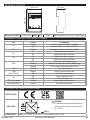
MODULE LAYOUT
LED STATUS LED meaning
RX Flashing Reception of packet completed on RS485
ON Anomaly / Check connection on RS485
TX Flashing Transmission of packet completed on RS485
IO1 ON Digital input/output activated
Off Digital input/output deactivated
IO2 ON Digital input/output activated
Off Digital input/output deactivated
PWR
ON The device is powered correctly
Flashing Waiting for IP address from DHCP (R-SG3 only)
Flashing No IP address congured (R-SG3-P only)
FL Flashing Load cell overload
COM
(Only R-SG3-P)
Flashing Pronet communication active
Off No Pronet communication
MD ON Factory calibration in use
Off Field calibration in use
ETH TRF (Yellow) Flashing Packet transit on Ethernet port
ETH LNK (Green) Flashing Ethernet port connected
SIGNALS VIA LED ON FRONT PANEL
Dimensions (LxHxD) 53.3 x 90 x 32.2
Weight
80 g Case Self-extinguishing UL94-V0 PC / ABS material
32.2 mm
53.3 mm
mm0,09
TECHNICAL SPECIFICATIONS
CERTIFICATIONS
INSULATION
POWER SUPPLY
Voltage: 10 – 40 Vdc; 19 – 28 Vac 50 – 60 Hz Absorption: Max: 1.5 W
WARNING
the maximum working voltage between any
terminal and ground must be less than 50
Vac / 75Vdc
1500 V~
Digital
I/O
RS485
ETH
Analogue
Input
Comm.
Comm.
Power
Supply

MI00599-1-EN INSTALLATION MANUAL 3/4
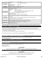
* In the case of “calibration with sample weight” mode, the accuracy is given by the linearity error (0.003% of the electric full scale)
ENVIRONMENTAL
CONDITIONS
Temperature: -20 ÷ + 65°C
Humidity: 30% ÷ 90% non condensing.
Storage temperature: -30 ÷ + 85°
Protection rating: IP20.
ASSEMBLY
IEC EN60715, 35mm DIN rail in vertical position.
CONNECTIONS
5 mm pitch removable screw terminals
ANALOGUE INPUT
CHARACTERISTICS
Input impedance: > 1MΩ
Full scale: ± 30mV ÷ ± 460mV
Error: 0.01% of the electrical full scale in “factory calibration” mode *
Thermal stability: 0.0010%/C° of full scale.
Cell supply voltage: 5 Vdc (supplied by the device)
Resolution: ADC 24bit
Response time with lter activated: 2 ÷ 850ms congurable
LOAD CELL
CHARACTERISTICS
4 or 6 wires;
Cell minimum impedance: 87 Ω equivalent (possibly deriving from several load cells)
Cell sensitivity: From ±1 mV/V to ±64 mV/V;
DIGITAL IN/OUT
Opto-insulated digital input: Min. voltage: 12 V / Max. voltage: 30 V
Opto-insulated digital output: Max. current: 50 mA / Max. voltage: 30 V
COMMUNICATION
Serial communication ports:
RS485, 1200
÷
115200 Baud
10/100Mbit/s Ethernet port
SETTING THE SW1 DIP-SWITCHES:
ModBUS CONNECTION RULES
1) Install the modules in the DIN rail (120 max)
2) Connect the remote modules using cables of an appropriate length. The following table shows cable length data:
- Bus length: maximum length of the Modbus network according to the Baud Rate. This is the length of the cables that connect
the two farthest modules (see Diagram 1).
- Derivation length: maximum length of a derivation 2 m (see Diagram 1).
For maximum performance, it is recommended to use special shielded cables, such as BELDEN 9841.
ETHERNET CONNECTION STANDARDS
Per il cablaggio Ethernet fra i dispositivi è previsto l’uso del cavo CAT5 o CAT5e non schermato;
CAT6 per ambienti industriali.
FACTORY IP ADDRESS (R-SG3 ONLY)
The module’s default IP address is static: 192. 168. 90. 101
WEB SERVER
Use the following credentials to access the Maintenance Web Server:
Default user: admin
Default password: admin
CAUTION
DO NOT USE DEVICES WITH THE SAME IP ADDRESS IN THE SAME ETHERNET NETWORK.
For operation and settings via DIP-SWITCH see the user manual available on the product webpage.
The DIP-switch settings are read only at boot time. At each change, perform a restart.
WARNING

MI00599-1-EN INSTALLATION MANUAL 4/4
CAUTION
The upper power supply limits must not be exceeded, as this could cause serious damage to the module. Switch the mod-
ule off before connecting inputs and outputs.
To meet the electromagnetic immunity requirements:
• use shielded signal cables;
• connect the shield to a preferential instrumentation earth system;
• separate shielded cables from other cables used for power installations (inverters, motors, induction ovens, etc...).
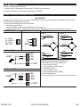
ELECTRICAL CONNECTIONS
Connection to the load cell via 4 or 6 wires:
The terminals have the following meaning:
8: Load cell positive supply
10: Load cell positive supply reading
12: Cell reading positive
9: Load cell negative supply
11: Load cell negative supply reading
13: Cell reading negative
For the connections, the use of screened cables is required.
POWER SUPPLY
DIGITAL INPUTS
DIGITAL OUTPUTS
RS485 LOAD CELL
4 wires 6 wires
Signal +
Sense -
-
Signal -
+
Sense +
8
10
12
11
9
13
PS BUTTON1
The tare is reset using the PS1 button.
To reset the tare it is necessary to hold down the PS1 button for three seconds.
The update of the value can be viewed via Webserver or ModBUS.
Excitation
Signal +
-
Signal -
+
8
10
12
11
9
13
Excitation
Excitation Excitation
A
B
GND
1
2
3
10 – 40 Vdc
19 – 28 Vac
50 – 60 Hz
Max: 1,5W
0V
DI 1
DI 2
+ V EXT
7
4
5
6
V EXT
V EXT
LOAD
0V
DO 1
DO 2
+ V EXT
7
4
5
6
LOAD
-
 1
1
-
 2
2
-
 3
3
-
 4
4


in altre lingue
- English: Seneca R-SG3 Installation guide
Altri documenti
-
Mettler Toledo IND780 (11 MB) Guida d'installazione
-
-
-
-
Eurotherm 3200 Manuale del proprietario
-
-
CARLO GAVAZZI WM4096 Manuale utente
-
WAGO ETHERNET Fieldbus Coupler/XTR Manuale utente
-
VIPA CPU 017-CEFPR00 Manuale del proprietario