
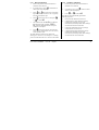
E
UR
O
T
H
E
R
M
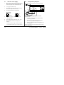
3200i
Process indicator
User Guide
Manuale di uso
Guía del usuario
ENG
ITA
SPA

This booklet includes:
User Guide (HA029005 Issue 2)
Manuale di uso (HA029005ITA Versione 2)
Guía del usuario (HA029005SPA Edición 2)

Part number HA029005. Issue 2.0 May-06. 1
3200i Series Process Indicators and Alarm Units
Applies to Model numbers 3216i, 32h8i and 3204i
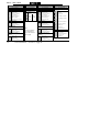
Contents
1. What Instrument Do I Have?.........................................................................................4
1.1 Unpacking Your Indicator ................................................................................................................... 5
1.2 Dimensions Front Views..................................................................................................................... 5
1.3 Dimensions – Side and Top Views ....................................................................................................... 6
1.4 Step 1: Installation ............................................................................................................................. 7
1.4.1 Panel Mounting the Indicator.................................................................................................................................................... 7
1.4.2 Panel Cut-out Sizes........................................................................................................................................................................ 7
1.4.3 Recommended minimum spacing of indicators................................................................................................................... 8
1.4.4 To Remove the Indicator from its Sleeve............................................................................................................................... 8
1.5 Ordering Code..................................................................................................................................... 9
2. Step 2: Wiring............................................................................................................ 10
2.1 Terminal Layout 3216i Indicator.........................................................................................................10
2.2 Terminal Layout 32h8i Indicator ........................................................................................................11
2.3 Terminal Layout 3204i Indicators .......................................................................................................12
2.4 Wire Sizes...........................................................................................................................................13
2.5 Sensor Input (Measuring Input) .........................................................................................................13
2.6 Outputs - 1/8 and 1/4 DIN Indicators .................................................................................................14
2.6.1 Output 1 & Output 4 (AA Relay) ............................................................................................................................................14
2.6.2 Output 3 Retransmission (Output 2 3216i) .........................................................................................................................15

2 Part number HA029005. Issue 2.0 May-06.
2.6.3 Transmitter Supply ...................................................................................................................................................................... 15
2.6.4
Digital Inputs A and B ................................................................................................................................................................ 15
2.6.5 Transducer Supply....................................................................................................................................................................... 15
2.7 Indicator Power Supply ..................................................................................................................... 16
2.8 Example Wiring Diagram ................................................................................................................... 16
2.9 Digital Communications (Optional) ................................................................................................... 17
2.10 Additional Connections for 3216i ...................................................................................................... 18
2.10.1 Input/Output 1 & Output 2 ............................................................................................................................................... 18
3. Safety and EMC Information .......................................................................................19
3.1 Installation Safety Requirements....................................................................................................... 20
4. Switch On ................................................................................................................... 24
4.1 New Indicator .................................................................................................................................... 24
4.1.1 To Re-Enter Quick Code Mode ............................................................................................................................................... 28
4.2 Pre-Configured Indicator or Subsequent Starts................................................................................. 28
4.3 Front panel layout ............................................................................................................................. 29
4.3.1 Alarm Indication .......................................................................................................................................................................... 30
4.3.2 Out of Range Indication ............................................................................................................................................................ 30
4.3.3 Sensor Break Indication............................................................................................................................................................. 30
4.3.4 Diagnostic Alarms........................................................................................................................................................................ 30
4.4 Operator Parameters in Level 1......................................................................................................... 31
4.4.1 Tare Correction ............................................................................................................................................................................ 32
5. Operator Level 2......................................................................................................... 33
5.1 To Enter Level 2 ................................................................................................................................. 33
5.1.1 To Return to Level 1................................................................................................................................................................... 33

Part number HA029005. Issue 2.0 May-06. 3
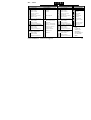
5.2 Level 2 Parameters .............................................................................................................................34
5.3
Strain Gauge Calibration ....................................................................................................................38
5.3.1 To configure the different modes:- .......................................................................................................................................38
5.3.2 Load Cell Calibration .................................................................................................................................................................. 39
5.3.3 Comparison Calibration .............................................................................................................................................................40
5.3.4 Shunt Calibration .........................................................................................................................................................................40
5.3.5 Manual Calibration......................................................................................................................................................................41
5.3.6 Automatic Calibration ................................................................................................................................................................ 41
5.3.7 Calibration Using a Digital Input .............................................................................................................................................42
5.4 Recipes ...............................................................................................................................................43
5.4.1 To Store Values in a Recipe...................................................................................................................................................... 43
5.4.2 To Load a Recipe .........................................................................................................................................................................43
5.5 FM and DIN 3440 Alarm Units............................................................................................................44
Issue Status of this Manual
Issue 2 of this manual applies to firmware version 1.03 and contains the following changes:-
Load cell and shunt calibration explained in more detail.
Separate ‘Set 2’ codes for 32h8i/3204i and 3216i for clarity
Add note on sensor break for transducers
Add note on FM DIN3440 indicators.

4 Part number HA029005. Issue 2.0 May-06.
Installation and Basic Operation
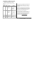
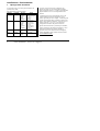
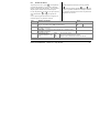
1. What Instrument Do I Have?
Thank you for choosing this 3200i series Process
Indicator.
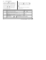
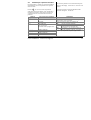
These are available as:-
Model Size Inputs Outputs
3216i 1/16
DIN
Thermocouple
Pt100 RTD
V/mA/mV
1 – Relay, Logic,
Analogue or dig in
2 – Relay, or
Analogue
4 Changeover
relay
32h8i 1/8
DIN
Thermocouple
Pt100 RTD
V/mA/mV
2 Digital
1 Changeover
relay
3 Retransmission
4. Changeover
relay
and Transmitter
PSU
32h8i/SG 1/8
DIN
Strain gauge As 32h8i
3204i 1/4
DIN
As 3216i As 32h8i
Relay outputs can be configured for alarm and events
and analogue retransmission of process variable. 2-
wire Modbus digital communications is available in
all models.
The indicator may have been ordered to a hardware
code only or pre-configured using an optional ‘Quick
Start’ code. The label fitted to the side of the sleeve
shows the ordering code of the indicator. If the Quick
Code shows ***** the indicator will need to be
configured when it is first switched on.
This User Guide takes you through step by step
instructions to help you to install, wire, configure and
use the indicator. For features not covered in this
User Guide, a detailed Engineering Manual, Part No
HA029006, and other related handbooks can be
downloaded from www.eurotherm.co.uk.

Part number HA029005. Issue 2.0 May-06. 5
1.1 Unpacking Your Indicator
The following items are included in the box:
• Indicator mounted in its sleeve
• Two panel retaining clips
• AN IP65 sealing gasket mounted on the sleeve
• Component packet containing a snubber for
each relay output and a 2.49Ω resistor for
current inputs (see section 2)
• This User Guide
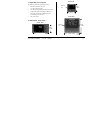
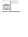
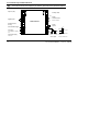
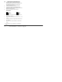
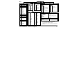
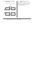
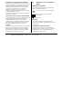
1.2 Dimensions Front Views
96mm (3.78in)
48mm
(1.89in)
Models 32h8i
48mm
(1.89in)
48mm
(1.89in)
Latching
ears
Model 3216i
96mm
(3.78in)
Model 3204i
Latching
ears
96mm (3.78in)

6 Part number HA029005. Issue 2.0 May-06.
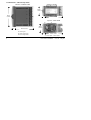
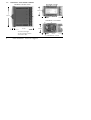
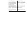
1.3 Dimensions – Side and Top Views
1 Latching ears
2 Panel retaining clip
3 IP65 Sealing Gasket
Side View –1/8 DIN & 1/4 DIN
90mm (3.54in)
d
96mm
(3.78in)
1
3
d
23
1
Top View
–
1/16 & 1/8 DIN
Side View
–
1/16 DIN
90mm (3.54in)
1
90mm (3.54in)
d
48mm
(1.89in)
48mm
(1.89in)
2
1
2
2
3
3
d = Fascia depth 1.25mm (0.5in)

Part number HA029005. Issue 2.0 May-06. 7
1.4 Step 1: Installation
This indicator is intended for permanent installation,
for indoor use only, and enclosed in an electrical
panel
Select a location which is subject to minimum
vibrations, the ambient temperature is within 0 and
55
o
C (32 - 131
o
F) and humidity 5 to 95% RH non
condensing.
The indicator can be mounted on a panel up to
15mm thick
To ensure IP65 and NEMA 4 front sealing against
dust and water, mount on a non-textured surface.
Please read the safety information in section 3
before proceeding. The EMC Booklet part number
HA025464 gives further installation information.
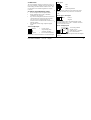
1.4.1 Panel Mounting the Indicator
1. Prepare a cut-out in the mounting panel to the
size shown. If a number of instruments are to
be mounted in the same panel observe the
minimum spacing shown.
2. Fit the IP65 sealing gasket behind the front
bezel of the indicator
3. Insert the indicator through the cut-out
4. Spring the panel retaining clips into place.
Secure the indicator in position by holding it
level and pushing both retaining clips forward.
5. Peel off the protective cover from the display
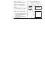
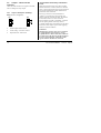
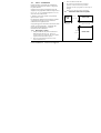
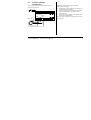
1.4.2 Panel Cut-out Sizes
45 mm
- 0.0 + 0.6
1.77 inch
-0.00, +0.02
45 mm
- 0.0 + 0.6
1.77 inch
-0.00, +0.02
Model
3216i
Model 32h8i
Model 3204i
92 mm
- 0.0 + 0.8
3.62 inch
-0.00, +0.03
92 mm - 0.0 + 0.8
3.62 inch -0.00, +0.03

8 Part number HA029005. Issue 2.0 May-06.
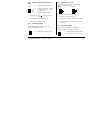
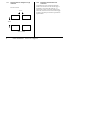
1.4.3 Recommended minimum spacing of
indicators.
Applies to all Model sizes
1.4.4 To Remove the Indicator from its
Sleeve
The indicator can be unplugged from its sleeve by
easing the latching ears outwards and pulling it
forward out of the sleeve. When plugging it back
into its sleeve, ensure that the latching ears click
back into place to maintain the IP65 sealing.
10mm (0.4 inch)
38mm (1.5 inch)
(Not to scale)

Part number HA029005. Issue 2.0 May-06. 9
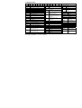
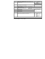
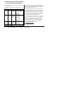
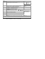
1.5 Ordering Code
1 2 3 4 5 6 7 8 9 10 11 12 13 14 Quick Start Code (see section 4)
8/9 Product/Manual Language
ENG English
FRA French
GER German
ITA Italian
SPA Spanish
7. Fascia colour/type
G Green
S Silver
6. Options
XXX Not fitted
(3216i only)
XXL Digital input A (not 32h8i/SG,
optional in 3216i)
2XL RS232 & Digital input A
(includes Dig In A except
32h8i/SG)
4XL RS485 & Digital input A
(includes Dig In A except
32h8i/SG)
11. Warranty
Standard XXXXX
Extended WL005
12. Certificates
None XXXXX
CERT1 Cert of
conformity
CERT2 5 Point Factory
calibration
13. Custom Label
XXXXX None
14. Special and Accessories
XXXXXX None
RES250 250Ω ; 0-5Vdc
OP
RES500 500Ω ; 0-10Vdc
OP
5. AA Relay (OP4)
R Relay (Form C)
4. Outputs (OP1, OP2, OP3)
LRXX OP1 Logic, OP2 Relay *
RRXX OP1 Relay, OP2 Relay *
LDXX OP1 Logic, OP2 Analogue *
DRXX OP1 Analogue, OP2 Relay *
RXXX OP1 Relay
(32h8i & 3204i only)
RXDX OP1 Relay, OP3 Analogue
(32h8i & 3204i only)
* 3216i only
10. Input Adaptor
XX None
V1 1-10Vdc
A1 mA Burden Resistor
(2.49Ω)
3. Power Supply
VL 24Vac/dc
VH 100–240Vac
2. Function
AL Standard Unit
FM FM Alarm Unit
DN DIN 3440 alarm unit
SG Strain Gauge Input 32h8i only
1. Model No.
3216i 1/16 DIN size
32h8i 1/8 DIN size (horizontal)
3204i 1/4 DIN size

10 Part number HA029005. Issue 2.0 May-06.
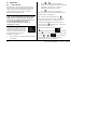
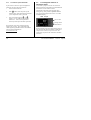
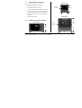
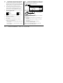
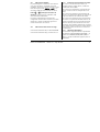
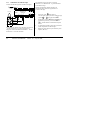
2. Step 2: Wiring
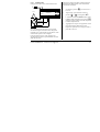
2.1 Terminal Layout 3216i Indicator
!
Ensure that you have the correct supply for your indicator. Check order code of the indicator supplied
806Ω
100KΩ
COM
A(+)
B(-)
Digital Communications
RS232
RS485
A
A relay (OP4)
AA
AB
AC
VI
V+
V-
1A
1B
2A
2B
L
N
CT
C
LA
HD
HE
HF
-
+
mV
+
-
Sensor Input
2.49Ω
T/C
Pt100 mA
-
+
+ +
- -
+
-
Line Supply 100 to 240Vac 50/60Hz
OR Low Voltage Supply 24Vac/dc
Input/Output 1
Output 2
Digital input A
10V Potential divider
module
Part No SUB21/IV10
-
+
10V
Input
Key to Symbols used in the wiring diagrams
Logic (SSR drive) output
Relay output
Contact input
mA analogue output

Part number HA029005. Issue 2.0 May-06. 11
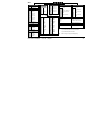
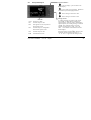
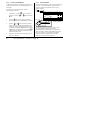
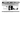
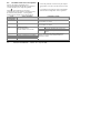
2.2 Terminal Layout 32h8i Indicator
!
Ensure that you have the correct supply for your indicator. Check order code of the indicator supplied
Cal
1
Signal | Txdcr Supply
Input Connections for
32h8i/SG Indicator - Strain gauge input
Note: Dig in A is not available with this indicator
- +
OP3 DC
Retrans
V/mA
24V
Transmitter
Supply
Dig in B
Output 1 (OP1)
Changeover
Relay
AA Relay
(OP4)
B(-) A(+) COM
Digital Comms
-
+
T/C
Sensor Input
Pt100
V- V+ VI LA C CT HF HE HD AC AB AA
N L 3D 3C 3B 3A LC LB 2B 2A 1B 1A
-
2.49Ω
mV/V
+
- +
Dig in A
- +
32h8i Indicator
Line Supply 100 to 240Vac 50/60Hz
OR
Low Voltage Supply 24Vac/dc
mA include the 2.49Ω load resisto
r
- +
Cal
2
Ext
-
Ext
+

12 Part number HA029005. Issue 2.0 May-06.
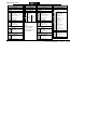
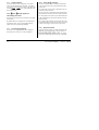
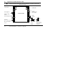
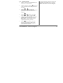
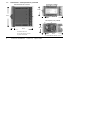
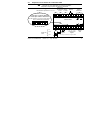
2.3 Terminal Layout 3204i Indicators
!
Ensure that you have the correct supply for your indicator. Check order code of the indicator supplied
10V Potential divider
module
Part No SUB21/IV10
Line Supply
100 to 240Vac 50/60Hz
OR
Low Voltage Supply
24Vac/dc
1A
1B
2A
2B
LB
LC
+
24V
-
24V Transmitter Supply
3A
3B
3C
3D
L
N
DC Retrans (OP3)
mA only
+
-
Digital Input B
Digital
Communications
RS232 or RS485
A
A Relay (OP4)
AA
AB
AC
HD
HE
HF
CT
C
LA
VI
V+
V-
COM
A(+)
B(-)
-
+
T/C
Sensor Input
Pt100 mA/mV
-
2.49Ω
+
Digital
input A
-
+
10V Input
Output 1 (OP1)
100KΩ
806Ω
3204i Indicator

Part number HA029005. Issue 2.0 May-06. 13
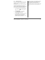
2.4 Wire Sizes
The screw terminals accept wire sizes from 0.5 to 1.5
mm (16 to 22AWG). Hinged covers prevent hands or
metal making accidental contact with live wires. The
rear terminal screws should be tightened to 0.4Nm
(3.5lb in).
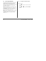
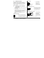
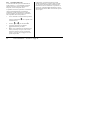
2.5 Sensor Input (Measuring Input)
• Do not run input wires with power cables
• When shielded cable is used, it should be
grounded at one point only
• Any external components (such as zener barriers)
connected between sensor and input terminals
may cause errors in measurement due to
excessive and/or un-balanced line resistance, or
leakage currents.
• Not isolated from the logic outputs & digital
inputs
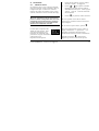
Thermocouple Input
• Use the correct
compensating cable
preferably shielded.
• It is not recommended to
connect two or more instruments to one thermocouple.
RTD Input
PRT
PRT
Lead compensation
• The resistance of the three wires must be the same.
The line resistance may cause errors if it exceeds
22Ω.
Linear mA, or mV Inputs
Positive
Negative
• For a mA input connect the 2.49Ω burden resistor
supplied between the V+ and V- terminals as shown.
For mV omit this resistor.
Linear Voltage Inputs
An external potential
divider, part no
SUB21/IV10, is available
for 3216i and 3204i.
Sensor break alarm does not operate when this adaptor
is fitted.
- Negative
+ Positive
V+
V-
2.49Ω
+
-
V+
V-
100KΩ
806Ω
+
0-10V
-
V+
V-
VI
V+
V-

14 Part number HA029005. Issue 2.0 May-06.
2.6 Outputs - 1/8 and 1/4 DIN
Indicators
32h8i and 3204i indicators are supplied as standard
with two changeover relay outputs.
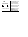
2.6.1 Output 1 & Output 4 (AA Relay)
Relay (Form C, changeover)
• Isolated output 240Vac CATII
• Contact rating:: 2A 264Vac resistive
• Output functions: Alarm/Event
* General Notes about Relays and Inductive
Loads
High voltage transients may occur when switching
inductive loads such as some contactors or solenoid
valves. Through the internal contacts, these transients
may introduce disturbances which could affect the
performance of the instrument.
For this type of load it is recommended that a
‘snubber’ is connected across the normally open
contact of the relay switching the load. The snubber
recommended consists of a series connected
resistor/capacitor (typically 15nF/100Ω). A snubber
will also prolong the life of the relay contacts.
A snubber should also be connected across the output
terminal of a triac output to prevent false triggering
under line transient conditions.
WARNING
When the relay contact is open, or it is connected
to a high impedance load, it passes a current
(typically 0.6mA at 110Vac and 1.2mA at 240Vac).
You must ensure that this current will not hold on
low power electrical loads. If the load is of this
type the snubber should not be connected.
OP4
AA
AB
AC
1A
1B
2A
OP1

Part number HA029005. Issue 2.0 May-06. 15
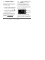
2.6.2 Output 3 Retransmission (Output 2
3216i)
• Isolated output 240Vac CATII
• Software configurable: 0-20mA
or 4-20mA plus 0-5V, 0-10V, 1-
5V and 2-10V.
• Max load resistance: 500Ω
• Calibration accuracy: +(<0.25% of reading +
<50µA
• Output functions: PV retransmission.
• Output 2 non-isolated on 3216i
2.6.3 Transmitter Supply
A fixed 24Vdc supply is available to power an
external transducer (not 3216i).
• Isolated output 240Vac CATII
2.6.4 Digital Inputs A and B
Digital input A is not available in 32h8i/SG and
optionally available on 3216i.
• Not isolated from the sensor input
• Switching: 12Vdc at 40mA max
• Contact open > 500Ω. Contact closed < 200Ω
• Input functions: Please refer to the list in the
quick codes.
2.6.5 Transducer Supply
In 32h8i/SG a 10Vdc supply is available as an
excitation voltage for a bridge type transducer
• Minimum load resistance 300Ω
• Isolated output 240Vac CATII
+
-
OP3
3A
3B
Dig In A
LA
C
Dig In B
LB
LC
+
-
3C
3D
+
-
Ext1
Ext2

16 Part number HA029005. Issue 2.0 May-06.
2.7 Indicator Power Supply
1. Before connecting the indicator to the power
line, make sure that the line voltage corresponds
to the description on the identification label.
2. Use copper conductors only.
3. The power supply input is not fuse protected.
This should be provided externally.
4. For 24V the polarity is not important.
• High voltage supply: 100 to 240Vac, -15%,
+10%, 50/60 Hz
• Low voltage supply: 24Vac/dc, -15%, +10%
• Recommended external fuse ratings are as
follows:-
For 24 V ac/dc, fuse type: T rated 2A 250V
For 100-240Vac, fuse type: T rated 2A 250V.
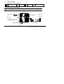
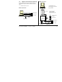
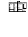
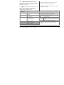
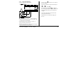
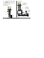
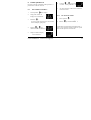
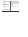
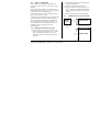
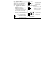
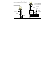
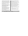
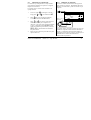
2.8 Example Wiring Diagram
This shows 32h8i connected to a strain gauge bridge.
Safety requirements for permanently connected
equipment state:
• A switch or circuit breaker shall be included in
the building installation
• It shall be in close proximity to the equipment
and within easy reach of the operator
• It shall be marked as the disconnecting device for
the equipment.
Note: a single switch or circuit breaker can drive more
than one instrument.
Line
Neutral
Power Supply
L
N
24V
24V
24
24
Signal
+
-
N
Fuse
L
N L 3D 3C 3B 3A LC LB 2B 2A 1B 1A
-
+
32h8i/SG Indicator
R
CAL
Strain
Gauge
Cal
1
Cal
2
Ext
-
Ext
+
- +
HE
HD
HF
AC AB AA
Txdcr
Suppl
y
Interna
l
FET
switch

Part number HA029005. Issue 2.0 May-06. 17
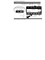
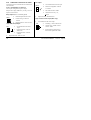
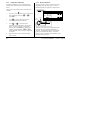
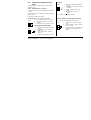
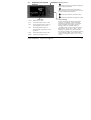
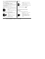
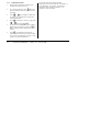
2.9 Digital Communications (Optional)
Digital communications uses the Modbus protocol.
The interface may be ordered as RS232 or RS485 (2-
wire).
• Isolated 240Vac CATII.
RS232 Connections
RS485 Connections
Com
Tx
Rx
HD Common
HE Rx A(+)
HF Tx B(-)
Local Ground
Screen
220Ω termination
resistor
* RS232/RS485 2-wire
communications converter
eg Type KD485
Daisy Chain to
further
instrument
Com
220Ω termination
resistor on last
instrument in the line
Twisted pairs
Tx Rx Com
HD Common
HE Rx A(+)
HF Tx B(-)
Rx Tx Com
Screen
RxB/
TxB
RxA/
TxA
*

18 Part number HA029005. Issue 2.0 May-06.
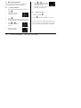
2.10 Additional Connections for 3216i
Connections for the 3216i indicator are similar to the
3216 controller.
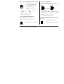
2.10.1 Input/Output 1 & Output 2
I/O1 may be configured as input or output.
Outputs can be logic (SSR drive), or relay, or mA dc.
Input is contact closure.
Relay Output (Form A, normally open)
• Isolated output 240Vac CATII
• Contact rating: 2A 264Vac
resistive
• Output functions: Alarm or event
Logic (SSR drive) Output
• Not isolated from the sensor
input
• Output ON state: 12Vdc at
40mA max
• Output OFF state: <300mV,
<100µA
• Output functions: Alarm or event
DC Output
• Not isolated from the sensor input
• Software configurable: 0-20mA
or 4-20mA.
• Max load resistance: 500Ω
• Calibration accuracy: 1%,
+
100µA
• Output functions: Retransmission.
Logic Contact Closure Input (OP1 only)
• Not isolated from the sensor input
• Switching: 12Vdc at 40mA max
• Contact open > 500Ω. Contact
closed < 150Ω
• Input functions: Please refer to
the list in the Quick Start codes.
OP1/2
1/2A
1/2B
+
-
OP1/2
1A
1B
OP1
+
-
1/2A
1/2B
OP1
1A
1B
La pagina si sta caricando...
La pagina si sta caricando...
La pagina si sta caricando...
La pagina si sta caricando...
La pagina si sta caricando...
La pagina si sta caricando...
La pagina si sta caricando...
La pagina si sta caricando...
La pagina si sta caricando...
La pagina si sta caricando...
La pagina si sta caricando...
La pagina si sta caricando...
La pagina si sta caricando...
La pagina si sta caricando...
La pagina si sta caricando...
La pagina si sta caricando...
La pagina si sta caricando...
La pagina si sta caricando...
La pagina si sta caricando...
La pagina si sta caricando...
La pagina si sta caricando...
La pagina si sta caricando...
La pagina si sta caricando...
La pagina si sta caricando...
La pagina si sta caricando...
La pagina si sta caricando...
La pagina si sta caricando...
La pagina si sta caricando...
La pagina si sta caricando...
La pagina si sta caricando...
La pagina si sta caricando...
La pagina si sta caricando...
La pagina si sta caricando...
La pagina si sta caricando...
La pagina si sta caricando...
La pagina si sta caricando...
La pagina si sta caricando...
La pagina si sta caricando...
La pagina si sta caricando...
La pagina si sta caricando...
La pagina si sta caricando...
La pagina si sta caricando...
La pagina si sta caricando...
La pagina si sta caricando...
La pagina si sta caricando...
La pagina si sta caricando...
La pagina si sta caricando...
La pagina si sta caricando...
La pagina si sta caricando...
La pagina si sta caricando...
La pagina si sta caricando...
La pagina si sta caricando...
La pagina si sta caricando...
La pagina si sta caricando...
La pagina si sta caricando...
La pagina si sta caricando...
La pagina si sta caricando...
La pagina si sta caricando...
La pagina si sta caricando...
La pagina si sta caricando...
La pagina si sta caricando...
La pagina si sta caricando...
La pagina si sta caricando...
La pagina si sta caricando...
La pagina si sta caricando...
La pagina si sta caricando...
La pagina si sta caricando...
La pagina si sta caricando...
La pagina si sta caricando...
La pagina si sta caricando...
La pagina si sta caricando...
La pagina si sta caricando...
La pagina si sta caricando...
La pagina si sta caricando...
La pagina si sta caricando...
La pagina si sta caricando...
La pagina si sta caricando...
La pagina si sta caricando...
La pagina si sta caricando...
La pagina si sta caricando...
La pagina si sta caricando...
La pagina si sta caricando...
La pagina si sta caricando...
La pagina si sta caricando...
La pagina si sta caricando...
La pagina si sta caricando...
La pagina si sta caricando...
La pagina si sta caricando...
La pagina si sta caricando...
La pagina si sta caricando...
La pagina si sta caricando...
La pagina si sta caricando...
La pagina si sta caricando...
La pagina si sta caricando...
La pagina si sta caricando...
La pagina si sta caricando...
La pagina si sta caricando...
La pagina si sta caricando...
La pagina si sta caricando...
La pagina si sta caricando...
La pagina si sta caricando...
La pagina si sta caricando...
La pagina si sta caricando...
La pagina si sta caricando...
La pagina si sta caricando...
La pagina si sta caricando...
La pagina si sta caricando...
La pagina si sta caricando...
La pagina si sta caricando...
La pagina si sta caricando...
La pagina si sta caricando...
La pagina si sta caricando...
La pagina si sta caricando...
La pagina si sta caricando...
La pagina si sta caricando...
La pagina si sta caricando...
La pagina si sta caricando...
La pagina si sta caricando...
La pagina si sta caricando...
La pagina si sta caricando...
La pagina si sta caricando...
La pagina si sta caricando...
La pagina si sta caricando...
La pagina si sta caricando...
-
 1
1
-
 2
2
-
 3
3
-
 4
4
-
 5
5
-
 6
6
-
 7
7
-
 8
8
-
 9
9
-
 10
10
-
 11
11
-
 12
12
-
 13
13
-
 14
14
-
 15
15
-
 16
16
-
 17
17
-
 18
18
-
 19
19
-
 20
20
-
 21
21
-
 22
22
-
 23
23
-
 24
24
-
 25
25
-
 26
26
-
 27
27
-
 28
28
-
 29
29
-
 30
30
-
 31
31
-
 32
32
-
 33
33
-
 34
34
-
 35
35
-
 36
36
-
 37
37
-
 38
38
-
 39
39
-
 40
40
-
 41
41
-
 42
42
-
 43
43
-
 44
44
-
 45
45
-
 46
46
-
 47
47
-
 48
48
-
 49
49
-
 50
50
-
 51
51
-
 52
52
-
 53
53
-
 54
54
-
 55
55
-
 56
56
-
 57
57
-
 58
58
-
 59
59
-
 60
60
-
 61
61
-
 62
62
-
 63
63
-
 64
64
-
 65
65
-
 66
66
-
 67
67
-
 68
68
-
 69
69
-
 70
70
-
 71
71
-
 72
72
-
 73
73
-
 74
74
-
 75
75
-
 76
76
-
 77
77
-
 78
78
-
 79
79
-
 80
80
-
 81
81
-
 82
82
-
 83
83
-
 84
84
-
 85
85
-
 86
86
-
 87
87
-
 88
88
-
 89
89
-
 90
90
-
 91
91
-
 92
92
-
 93
93
-
 94
94
-
 95
95
-
 96
96
-
 97
97
-
 98
98
-
 99
99
-
 100
100
-
 101
101
-
 102
102
-
 103
103
-
 104
104
-
 105
105
-
 106
106
-
 107
107
-
 108
108
-
 109
109
-
 110
110
-
 111
111
-
 112
112
-
 113
113
-
 114
114
-
 115
115
-
 116
116
-
 117
117
-
 118
118
-
 119
119
-
 120
120
-
 121
121
-
 122
122
-
 123
123
-
 124
124
-
 125
125
-
 126
126
-
 127
127
-
 128
128
-
 129
129
-
 130
130
-
 131
131
-
 132
132
-
 133
133
-
 134
134
-
 135
135
-
 136
136
-
 137
137
-
 138
138
-
 139
139
-
 140
140
-
 141
141
-
 142
142
-
 143
143
-
 144
144


Eurotherm 3200 Manuale del proprietario
- Tipo
- Manuale del proprietario
- Questo manuale è adatto anche per
in altre lingue
- English: Eurotherm 3200 Owner's manual
- español: Eurotherm 3200 El manual del propietario
Documenti correlati
-
Eurotherm 3200 Guida d'installazione
-
-
-
-
-
-
-
-
-
Altri documenti
-
Ascon tecnologic D9 Guida d'installazione
-
-
KRAFTWERK 31004 Istruzioni per l'uso
-
Omega CN243 Series Manuale del proprietario
-
-
-
CRYSTAL XP2i Istruzioni per l'uso
-
Tyco HVR800 Manuale utente
-
Seneca R-SG3 Guida d'installazione
-
Magnetrol Kotron 805 Istruzioni per l'uso