ProLights STARK1000 Manuale utente
- Categoria
- Stroboscopi
- Tipo
- Manuale utente

USER MANUAL
MANUALE UTENTE
STARK1000
MOVING HEAD
EN - IT

STARK1000
2
All rights reserved by Music & Lights S.r.l. No part of this instruction manual may be
reproduced in any form or by any means for any commercial use.
In order to improve the quality of products, Music&Lights S.r.l. reserves the right to modify the
characteristics stated in this instruction manual at any time and without prior notice.
All revisions and updates are available in the ‘manuals’ section on site www.musiclights.it
REV. 08-03/19 - FW: 2.1.00

1
STARK1000
Packing content
• STARK1000
• Mount bracket
• User manual
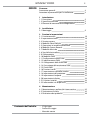
TABLE OF CONTENTS
Safety
General instructions
Warnings and installation precautions
1 Introduction
1. 1 Description
1. 2 Technical specifications
1. 3 Operating elements and connections
2 Installation
2. 1 Mounting
3 Functions and settings
3. 1 Operation
3. 2 Basic
3. 3 Menu structure
3. 4 Slave Receive mode
3. 5 Operation in automatic mode
3. 6 Scenes Record mode
3. 7 Music mode
3. 8 Sensitivity microphone
3. 9 Linking
3. 10 DMX mode
3. 11 DMX configuration
3. 12 DMX addressing
3. 13 Connection of the DMX line
3. 14 Construction of the DMX termination
3. 15 DMX control
3. 16 Channel Function
3. 17 Wireless control settings
3. 18 Fixture settings
3. 19 Lamp settings
3. 20 Display settings
3. 21 Special functions
3. 22 Fixture information
4 Maintenance
4. 1 Maintenance and cleaning the unit
4. 2 Fuse replacement
4. 3 Trouble shooting
2
2
3
3
6
7
8
8
9
11
11
13
13
13
14
14
14
14
16
16
17
28
29
30
30
31
31
32
33
33
34

STARK1000
2
WARNING! Before carrying out any operations with the unit, carefully read this instruction
manual and keep it with cure for future reference. It contains important information about
the installation, usage and maintenance of the unit.
SAFETY
General instruction
• The products referred to in this manual conform to the European Community Directives and are there-
fore marked with .
• The unit is supplied with hazardous network voltage (230V~). Leave servicing to skilled personnel only.
Never make any modifications on the unit not described in this instruction manual, otherwise you will
risk an electric shock.
• Connection must be made to a power supply system fitted with efficient earthing (Class I appliance ac-
cording to standard EN 60598-1). It is, moreover, recommended to protect the supply lines of the units
from indirect contact and/or shorting to earth by using appropriately sized residual current devices.
• The connection to the main network of electric distribution must be carried out by a qualified electrical
installer. Check that the main frequency and voltage correspond to those for which the unit is designed
as given on the electrical data label.
• This unit is not for home use, only professional applications.
• Never use the fixture under the following conditions:
- in places wet;
- in places subject to vibrations or bumps;
- in places with an ambient temperature of over 45°C.
• Make certain that no inflammable liquids, water or metal objects enter the fixture.
• Do not dismantle or modify the fixture.
• All work must always be carried out by qualified technical personnel. Contact the nearest sales point for
an inspection or contact the manufacturer directly.
• If the unit is to be put out of operation definitively, take it to a local recycling
plant for a disposal which is not harmful to the environment.
Warnings and installation precautions
• If this device will be operated in any way different to the one described in this manual, it may suffer
damage and the guarantee becomes void. Furthermore, any other operation may lead to dangers like
short circuit, burns, electric shock, etc.
• Before starting any maintenance work or cleaning the projector, cut off power from the main supply.
• Always additionally secure the projector with the safety rope. When carrying out any work, always com-
ply scrupulously with all the regulations (particularly regarding safety) currently in force in the country
in which the fixture’s being used.
• For inside use only. Not designed for outside use.
• The minimum distance between the fixture and surrounding walls must be more than 50 cm and the
air vents at the housing must not be covered in any case.
• Install the fixture in a well ventilated place.
• Keep any inflammable material at a safe distance from the fixture.
• The maximum temperature that can be reached on the external surface of the fitting, in a thermally
steady state, is high. After power off, please cool down over 15 minutes.
• Shields, lenses or ultraviolet screens shall be changed if they have become damaged to such an extent
that their effectiveness is impaired.
• The lamp (LED) shall be changed if it has become damaged or thermally deformed.
• Never look directly at the light beam. Please note that fast changes in lighting, e. g. flashing light, may
trigger epileptic seizures in photosensitive persons or persons with epilepsy.

3
STARK1000
- 1 - INTRODUCTION
1.1 DESCRIPTION
STARK1000 is a new generation, high output, LED wash light designed to bring the workhorse LED wash
light up-to-date. Featuring 19 of Osrams new 40W RGBW Ostar LEDs it delivers massive output with a
huge colour range and an extensive toolkit of effects.
1.2 TECHNICAL SPECIFICATIONS
LIGHT SOURCE
• Source: 19x40W RGBW Osram Ostar LEDs
• CT: Tunable 2000K~10000K
• Lux: (4°) 99943lux @3m full
• Lux: (4°) 35979lux @5m full
• Source life expectancy: >50.000 h
OPTICS
• Zoom: 4° - 45° motorised linear zoom
• Lens diameter: 275mm
• Lens type: high-quality glass lens optics
COLOUR SYSTEM
• Colour mixing: RGBW/FC
• CTC: CTC control through independent DMX channel
• White presets: 2000~10000K
• Colour wheel: virtual colour wheel with presets
• Macros: several pre-build pixel macros with adjustable speed
DYNAMIC EFFECTS
• Pixel patterns: pre-programmed dynamic and static patterns
• FX generator: adjustable foreground/background colour, index, speed, direction
BODY
• Pan angle: 540/630°
• Tilt angle: 233°
• Pan/Tilt resolution: 16 bit
• Feedback: automatic repositioning after accidental movement
• Body: aluminium structure with hi-resistance polycarbonate cover
• Body colour: black
CONTROL
• Protocols: DMX512, RDM, Art-Net,W-DMX
• DMX channels: 16 / 26 / 27 /36 / 98 channel
• Pixel control: pixel2pixel control
• W-DMX: included, wireless solution receiver
• RDM: RDM ready for fixture remote monitor and settings
• Display: LCD high resolution colour display with autoflip

STARK1000
4
• Firmware upgrade: yes, via USB-DMX interface (UPBOX2) not included
• Hibernation: power safe mode when lost DMX
• Master/Slave: for synchronized operation of more units linked in a chain
ELECTRONICS
• Dimmer: linear 0~100% electronic dimmer
• Dimmer curves: different dimming curves available
• Strobe / shutter: 1-30 Hz, electronic
• Battery backup: battery backup for user operation without connecting to the main power
• Operating temperature: -10° ~ +45°
• Flicker: flicker free operation
ELECTRICAL
• Power supply: 100-240V – 50/60Hz
• Power consumption (at 230V): 615W
• Power consumption (at 120V): 615W
PHYSICAL
• Cooling: combination of heat pipe cooling system and low noise fan
• Sospension and fixing: any position with quick-lock omega brackets
• Pan / tilt lock: pan / tilt locking for transportation and maintenance
• Signal connection: Amphenol XLR 5p IN/OUT connectors
• Data connection: Art-Net RJ45 IN/OUT
• Power connection: Neutrik powerCON TRUE1 IN connector
• IP rating: 20
• Dimensions (WxHxD): 430.5x563.1x247mm
• Weight: 18kg

5
STARK1000
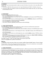
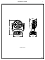
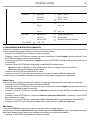
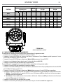
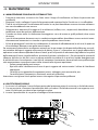
Technical drawing
Fig.1
235
327.8
563.1
247

STARK1000
6
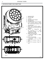
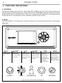
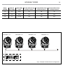
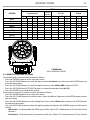
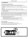
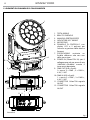
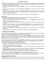
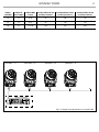
1. MOVING HEAD
2. ROTARY ARM
3. HANDLE
4. LED INDICATOR "WDMX"
5. MICROPHONE
6. CONTROL PANEL with LCD display
and 5 button used to access
the control panel functions and
manage them.
7. MAIN FUSE HOLDER: replace a
burnt-out fuse by one of the same
type only.
8. POWER IN (PowerCON IN):
for connection to a socket
(100-240V~/50-60Hz) via the
supplied mains cable.
9. DMX OUT (5-pole XLR):
1 = ground, 2 = DMX-, 3 = DMX+,
4 N/C, 5 N/C
10. DMX IN (5-pole XLR):
1 = ground, 2 = DMX-, 3 = DMX+,
4 N/C, 5 N/C
11. EtherCON connector Signal IN/
OUT
12. EtherCON connector Signal IN/
OUT
1.3 OPERATING ELEMENTS AND CONNECTIONS
Fig.2
View A
View B
1
2
A
B
3
4
5
6
11
9
7
8
12 10

7
STARK1000
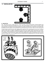
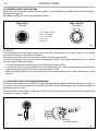
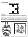
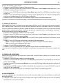
2.1 MOUNTING
The may be set up on a solid and even surface. By means of the fixing facilities of the baseplate, the
unit can also be mounted upside down to a cross arm. The base plate is shown in fig.3. For fixing, stable
mounting clips are required. According to the figure, the bolts of the brackets are placed into the openings
provided in the base plate and turned clockwise until they lock (to the stop). Always ensure that the unit
is firmly fixed to avoid vibration and slipping while operating. The mounting place must be of sufficient
stability and be able to support a weight of 10 times of the unit’s weight. When carrying out any installa-
tion, always comply scrupulously with all the regulations (particularly regarding safety) currently in force
in the country in which the fixture’s being used. Always additionally secure the projector with the safety
rope from falling down. For this purpose, fasten the safety rope at a suitable position so that the maximum
fall of the projector will be 20 cm.
Fig.3
ALISCAFF
CLAMP
SAFETY
CABLE
OMEGA
BRACKETS
- 2 - INSTALLATION

STARK1000
8
- 3 - FUNCTIONS AND SETTINGS
3.1 OPERATION
Connect the supplied main cable to a socket (100-240V~/50-60Hz). The unit will run built-in program to
reset all motors to their home position. Shortly after that the STARK1000 is ready for operation. To switch
off, disconnect the mains plug from the socket. For a more convenient operation it is recommended to
connect the unit to a socket which can be switched on and off via light switch.
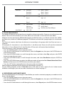
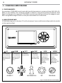
3.2 BASIC
The STARK1000 has a LCD display and 5 button used to access the control panel functions and manage
them (fig.4).
Fig.4 - Functions of the buttons and display icons
CONNECT
LIGHT
INFORMATION
SET
PROGRAM
LEFT RIGHT UP DOWN ENTER BATTERY
Return to the top
level
Commute from
units, tens, hundred
in the menu
Increases the value
displayed or passes
to the previous item
in a menu
Decreases the value
displayed or passes
to the next item in
the menu
Confirms the
displayed value,
or activates the
displayed function,
or enters the
successive menu
Used to activate the
backup battery. It
allows to switching
display interface
without main power

9
STARK1000
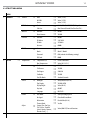
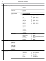
3.3 MENU STRUCTURE
MENU
1 CONNECT
ð
Address
ð
DMX
ð
Value (1-512)
W-DMX
ð
Value (1-512)
Artnet
ð
Value (1-512)
DMX Mode
ð
Mode
ð
WASH / FX / FX-16BIT/ PIXFX/ Ring /User
Edit User
ð
Max Channel/Control/Pan/Pan Fine/Tilt/...
Wireless
ð
DMX Out
ð
ON/OFF
Reset Connect
ð
YES/NO
Ethernet
ð
DMX Out
ð
ON/OFF
IP Address
ð
2.XX.XX.01
IP Mask
ð
255.0.0.0
Universe
ð
00000
RDM ID
ð
Name
ð
Fixture ID Name
Mode
ð
Mode1 / Mode2
Password
ð
050 (unlocks the following settings)
PID Code
ð
00001
2 SET UP
ð
Temperature
ð
Temperature C/F
ð
Celsius/Fahrenheit
Max Temperature
ð
Value (60°-139° C)
Movement
ð
Pan Reverse
ð
YES/NO
Tilt Reverse
ð
YES/NO
Pan Degree
ð
540/630
Feedbacks
ð
YES/NO
Pan/Tilt Mode
ð
Standard/Smooth
Screen
ð
Backlight
ð
Always On/Min (01-99)
Flip Display
ð
YES/NO/AUTO
Display Bright
ð
Value (00-31)
Key Lock
ð
ON/OFF
Language
ð
EN/FR/SP...
Fixture
ð
Fans Mode
ð
Auto Speed/High Speed
No Signal
ð
Close/Hold/Auto/Music
Hibernation
ð
Disable/Min (01-99)
Theatre Mode
ð
Yes/No
Adjust
ð
Control, Pan, Pan Fine,
Tilt, Tilt Fine, Pan&Tilt
Speed, Shutter, Dimmer,
Dimmer Fade, [...]
ð
Value (000-255) for each function

STARK1000
10
3 ADVANCED
ð
Reset
ð
All
Pan & Tilt
:
Dimmer Curve
ð
New Mode
Old Mode
Halogen Emulation
ð
HB/3200K/5600K/6000K
Calibration
ð
Password
ð
050 (unlocks the following settings)
Pan
ð
Value (-128-127)
Tilt
ð
Value (-128-127)
1Led Red
ð
Value (-128-127)
1Led Green
ð
Value (-128-127)
1Led Blue
ð
Value (-128-127)
2Led Red
ð
Value (-128-127)
2Led Green
2Led Blue
......
19Led Red
19Led Green
19Led Blue
Reload Default
ð
Basic Reload
ð
ON/OFF
Program Reload
ð
ON/OFF
Password
ð
050 (unlocks the following settings)
Private Reload
ð
ON/OFF
All Reload
ð
ON/OFF
4 INFORMATION
ð
Time I nfo.
Temperature
Fans Speed
Channel Value
Error Message
Fixture Model
Software Ver.
5 STAND ALONE
ð
Play
ð
DMX Receive
Slave Receive
ð
Part 1-2-3 Receive
Sequence
ð
Alone/Master
Music
ð
Alone/Master
Mic Sens.
ð
Value (00-99%)

11
STARK1000
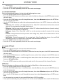
3.4 SLAVE RECEIVE MODE
This mode will allow you to link up the units together without a controller. Choose a unit to function as the
Master. The unit must be the first unit in line; other units will work as slave with the same effect.
A Master unit can send up to 3 different data groups to the Slave units, i.e. a Master unit can start 3 differ-
ent Slave units, which run 3 different programs. The Master unit sends the 3 program parts in a continuous
loop.
The Slave unit receives data from the Master unit according to the group which the Slave unit was as-
signed to.
For example, if a slave device is set to Receive Part 1, the Master unit Slave unit will send the automated
Chase Part 1; if set to Receive Part 2, the Chase Part 2 Slave units will receive from the Master.
To set the drive as a slave, proceed as follows:
• Press the ENTER button to access the main menu.
• Press the UP/DOWN button to scroll the menu, select the Program icon, then press the ENTER button to
enter the next menu.
• Press the UP/DOWN button to scroll through the menu, and then select Play and press the ENTER
button to enter the next menu.
• Press the UP/DOWN button to scroll through the menu, and select Slave Receive and press ENTER to
confirm.
• Press the UP/DOWN button to select the different modes of operation Part 1 Receive/Receive Part 2/Part 3
Receive, and then press the ENTER button to confirm your choice.
• Press the LEFT button repeatedly to exit the menu and save changes.
Select the desired program on the master unit (described in section 3.5).
Use the DMX connectors of the STARK1000 and an XLR cable to form a chain of units. Under certain
conditions and lengths you want to make a termination as shown on page 17.
3.5 OPERATIONS IN AUTOMATIC MODE
The unit independently runs through its show. Before you send an automatic program you need to set the
drive as Master/Alone:
• Press the ENTER button to access the main menu.
• Press the UP/DOWN button to scroll the menu, select the Program icon, then press the ENTER button to
enter the next menu.
• Press the UP/DOWN button to scroll through the menu, select Play and press the ENTER button to enter
Select Chase
ð
Chase Part 1
ð
Chase 1 - Chase 8
Chase Part 2 Chase 1 - Chase 8
Chase Part 3
ð
Chase 1 - Chase 8
Edit Chase
ð
Chase 1
ð
Step 1 - 64
Chase 2 Step 1 - 64
....
Chase 8
ð
Step 1 - 64
Edit Scenes
ð
Edit Scenes 001
ð
Pan/Pan Fine/Tilt/Tilt Fine/...
Edit Scenes ...
ð
Pan/Tilt/ Gobo1...
Edit Scenes 250
ð
Fade TIme, Scene Time, DMX Input
Scenes Record
ð
Sc XX - Sc XX

STARK1000
12
the next menu.
• Press the UP/DOWN button to scroll through the menu, select Sequence and press ENTER to confirm
your choice.
• Press the UP/DOWN button to select the mode of operation:
- Master, if the unit is connected in series with other units and it acts as the Master;
- Alone, if the unit is not connected to other units.
• Press the ENTER button to confirm your choice.
• Press the LEFT button repeatedly to exit the menu and save changes.
The unit will go into automatic mode by executing the program automatically.
Select Chase
The function Select Chase lets you choose the automatic program to actually run.
• Press the ENTER button to access the main menu.
• Press the UP/DOWN button to scroll the menu, select the Program icon, then press the ENTER button to
enter the next menu.
• Press the UP/DOWN button to scroll through the menu, select Select Chase and press the ENTER button
to enter the next menu.
• Press the UP/DOWN button to scroll through the menu, then select Chase Part 1/Chase Part 2/Chase Part 3
and press ENTER to confirm.
• Press the UP/DOWN button to select Chase1-Chase8, and press the ENTER button to confirm.
• Press the LEFT button repeatedly to exit the menu and save changes.
Edit Chases
The function Edit Chases allows you to create automatic pre-programmed show.
The automatic programs Chase Part1/2/3 are each divided into Chase1-Chase8. Each Chase can be composed
of 1-64 step that can be configured through the following procedure:
• Press the ENTER button to access the main menu.
• Press the UP/DOWN button to scroll the menu, select the Program icon, then press the ENTER button to
enter the next menu.
• Press the UP/DOWN button to scroll through the menu, select Edit Chases and press the ENTER button
to enter the next menu.
• Press the UP/DOWN button to scroll through the menu, select Edit Chase 1 - Edit Chase 8, then press the
ENTER button to confirm.
• Press the UP/DOWN button to select the Step 01 - Step 64, and press ENTER to confirm.
• Press the UP/DOWN button to select the Scene you want to set for the Step chosen, and then press
ENTER to confirm.
• Press the LEFT button repeatedly to exit the menu and save changes.
Edit Scenes
The function Edit Scenes allows you to create individual scenes to be included in the Chase Step.
• Press the ENTER button to access the main menu.
• Press the UP/DOWN button to scroll the menu, select the Program icon, then press the ENTER button to
enter the next menu.
• Press the UP/DOWN button to scroll through the menu, select Edit Scenes and press the ENTER button
to enter the next menu.
• Press the UP/DOWN button to scroll through the menu, select Edit Scene 001 - Edit Scene 250, then press the
ENTER button to confirm.
• Press the UP/DOWN button to select the desired function you want to edit (Control, Pan, Tilt, etc..), Then
press the ENTER button to confirm.
• Press the UP/DOWN button to change the value of the function, then press the ENTER button to

13
STARK1000
confirm.
• Press the LEFT button repeatedly to exit the menu and save changes.
3.6 SCENES RECORD MODE
STARK1000 is equipped with a built-in DMX recorder by which you can transmit the programmed scenes
from your DMX-controller to the device. Proceed as follows to store the sequence of scenes in the unit.
• Press the ENTER button to access the main menu.
• Press the UP/DOWN button to scroll through the menu, select the Program icon, then press the ENTER
button to enter the next menu.
• Press the UP/DOWN button to scroll through the menu, select Scenes Record and press the ENTER button
to enter the next menu.
• Press the UP/DOWN button to adjust the scene at the beginning and end to be inserted in the auto-
matic program, then press the ENTER button to confirm.
• Press the LEFT button repeatedly to exit the menu and save changes.
When recalling scenes from the controller will automatically be transmitted to the device.
3.7 MUSIC MODE
In music mode, via its integrated microphone, the unit can be controlled by music with a clear rhythm in
the bass range. If the music control should not work optimally, increase the volume or reduce the distance
between the sound source and the light effect unit or alternatively increase the sensitivity of the micro-
phone.
• Press the ENTER button to access the main menu.
• Press the UP/DOWN button to scroll the menu, select the Program icon, then press the ENTER button to
enter the next menu.
• Press the UP/DOWN button to scroll through the menu, select Play and press the ENTER button to enter
the next menu.
• Press the UP/DOWN button to scroll through the menu, select Music and press ENTER to confirm.
• Press the UP/DOWN button to select the mode of operation:
- Master, if the mobile head is connected in series to other units, and it performs the Master function;
- Alone, if the fixture is not connected to other units.
• Press the ENTER button to confirm your choice.
• Press the LEFT button repeatedly to exit the menu and save changes.
The unit will go into music mode by executing an automatic program to the rhythm of music.
3.8 SENSITIVITY MICROPHONE
Select this function to set the value of the sensitivity of the microphone for use with a music control:
• Press the ENTER button to access the main menu.
• Press the UP/DOWN button to scroll the menu, select the Set icon, then press the ENTER button to enter
the next menu.
• Press the UP/DOWN button to scroll through the menu, select UI Set, and press the ENTER button to
enter the next menu.
• Press the UP/DOWN button to scroll through the menu, then select Mic Sens. and press ENTER to confirm.
• Press the UP/DOWN button to adjust the level of sensitivity of the microphone, and then press the
ENTER button to confirm your choice.
• Press the LEFT button repeatedly to exit the menu and save changes.

STARK1000
14
3.9 LINKING
Several units may be interconnected in order to control all further slave units to the same effect of the
master unit.
1. Connect the DMX OUT of the master unit via 5-pole XLR cable to the DMX IN of the first slave unit.
2. Connect the DMX OUT of the first slave unit to the DMX IN of the second slave unit, etc. until all units
are connected in a chain.
3.10 DMX MODE
To enter the DMX mode, follow these steps:
• Press the ENTER button to access the main menu.
• Press the UP/DOWN button to scroll the menu, select the Connect icon, then press the ENTER button to
enter the next menu.
• Press the UP/DOWN button to scroll through the menu, select the DMX Address and press the ENTER key.
• Press the arrow keys to select the desired value (001-512).
• Press the ENTER key to confirm the setting.
• Press the LEFT button repeatedly to exit the menu and save changes.
3.11 DMX CONFIGURATION
The STARK1000 has 5 DMX channel configurations which can be accessed from the control panel.
• Press the ENTER button to access the main menu.
• Press the UP/DOWN button to scroll the menu, select the Set icon, then press the ENTER button to enter
the next menu.
• Press the UP/DOWN button to scroll through the menu, select Users and press the ENTER button to
enter the next menu.
• Press the UP/DOWN button to scroll through the menu, select User Mode and press ENTER to confirm
your choice.
• Use the UP/DOWN button to select the desired DMX channel configuration (Wash, FX, PIXFX, FX-16BIT, Ring,
User), then press the ENTER button to confirm your choice.
• Press the LEFT button repeatedly to exit the menu and save changes.
The tables on page 17 show the mode of operation and their values DMX.
The unit is equipped with 5-pole XLR connections.
Edit User
The Edit User, in the same menu, allows you to create a profile of personalized functions. You can change
the parameters of the various functions (Control, Pan, Tilt, etc.). Once you’ve created your custom profile,
you can use it by selecting the USER mode as described above.
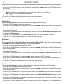
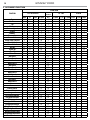
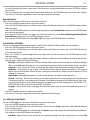
3.12 DMX ADDRESSING
For operation via light control unit with DMX512 protocol, is sufficient connect the controller to STARK1000.
To able to operate the STARK1000 with a light controller, adjust the DMX start address for the first a DMX
channel. If e. g. address 33 on the controller is provided for controlling the function of the first DMX chan-
nel, adjust the start address 33 on the STARK1000. The other functions of the light effect panel are then
automatically assigned to the following addresses.
An example with the start address 33 is shown below:

15
STARK1000
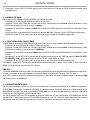
Fig.5 - Example 16 DMX channels configuration
DMX Address: 96DMX Address: 64DMX Address: 33 DMX Address: 80
. . . . . . . . . . . .
DMX512 Controller
Numero
canali DMX
Indirizzo di
start (esempio)
Indirizzo DMX
occupati
Prossimo indirizzo di start
possibile per unità n°1
Prossimo indirizzo di start
possibile per unità n°2
Prossimo indirizzo di start
possibile per unità n°3
16 33 33-48 64 80 96
26 33 33-58 84 110 136
98 33 33-130 228 326 424

STARK1000
16
Fig.6
3.13 CONNECTION OF THE DMX LINE
DMX connection employs standard XLR connectors. Use shielded pair-twisted cables with 120Ω imped-
ance and low capacity.
The following diagram shows the connection mode:
ATTENTION
The screened parts of the cable (sleeve) must never be connected to the system’s earth, as this would
cause faulty fixture and controller operation.
Over long runs can be necessary to insert a DMX level matching amplifier.
For those connections the use of balanced microphone cable is not recommended because it cannot
transmit control DMX data reliably.
• Connect the controller DMX input to the DMX output of the first unit.
• Connect the DMX output to the DMX input of the following unit. Connect again the output to the input
of the following unit until all the units are connected in chain.
• When the signal cable has to run longer distance is recommended to insert a DMX termination on the
last unit.
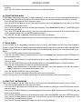
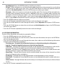
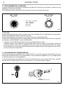
3.14 CONSTRUCTION OF THE DMX TERMINATION
The termination avoids the risk of DMX 512 signals being reflected back along the cable when they reach-
es the end of the line: under certain conditions and with certain cable lengths, this could cause them to
cancel the original signals.
The termination is prepared by soldering a 120Ω 1/4 W resistor between pins 2 and 3 of the 5-pin male XLR
connector, as shown in figure.
DMX - OUTPUT
XLR socket
DMX - INPUT
XLR plug
Pin1 : GND - Shield
Pin2 : - Negative
Pin3 : + Positive
Pin4 : N/C
Pin5 : N/C
Fig.7
Example:
5 pin XLR connector

17
STARK1000
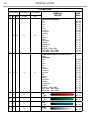
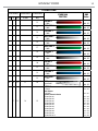
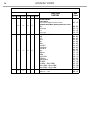
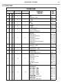
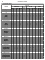
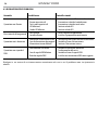
3.15 DMX CONTROL
STARK1000
V1.2.00 and above V2.0.04 and above V2.1.00 and above
STARK 1000
FUNCTION
DMX
Value
Wash FX Pixfx Fx-16bit Ring
1 1 1 1 1
PAN
Pan coarse 0~100%
000 - 255
2 2 2 2 2
PAN fine
0~100%
000 - 255
3 3 3 3 3
TILT
0~100%
000 - 255
4 4 4 4 4
TILT Fine
0~100%
000 - 255
5 5 5 5 5
MOVEMENT SPEED
Fastest to slowest
Movement with Blackout
000 - 247
248 - 255
6 6 6 6 6
SHUTTER
Shutter closed
Strobe effect slow to fast
Shutter open 1
Pulse-effect in sequences
Shutter open 2
Random strobe effect slow to fast
Shutter open 3
000 - 010
011 - 082
083 - 093
094 - 163
164 - 174
175 - 244
245 - 255
7 7 7 7 7
DIMMER
Dimmer 0% ~ 100%
000 - 255
8
DIMMER FINE
Dimmer fine 0% ~ 100%
8 8 9 8
DIMMER FADE
Snap 0% to 100% fade out
000 - 255
8 9 9 10 9
COLOR FUNCTION
No Function
White presets function
Forward Spin
Reverse Spin
Continuous
Color Bounce Function
TBD
000 - 015
016 - 031
032 - 047
048 - 063
064 - 079
080 - 111
112 - 255
9 10 10 11 10
VIRTUAL COLOR 1
White Presets
White 2000K ~ 2700K
White 2700K ~ 3200K
White 3200K ~ 4200K
White 4200K ~ 5600K
White 5600K ~ 8000K
White 8000K ~ 10000K
Forward Spin
Rainbow Effect (Slow to Fast)
Reverse Spin
Rainbow Effect (Slow to Fast)
000 - 155
156 - 175
176 - 195
196 - 215
216 - 235
236 - 255
000 - 255
000 - 255

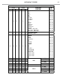
STARK1000
18
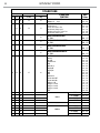
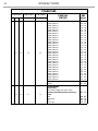
STARK1000
V1.2.00 and above V2.0.04 and above V2.1.00 and above
STARK 1000
FUNCTION
DMX
Value
Wash FX Pixfx Fx-16bit Ring
9 10 10 11 10
Continuous & Color Bounce
Black
Red
Green
Blue
White
Pastel Red
Pastel Green
Pastel BLue
Cyan
Magenta
Yellow
Light Yellow
Light BLue
Light Magenta
Full White
Full White ~ White 3200K
White 3200K ~ White 4200K
White 4200K ~ White 5600K
000 - 000
001 - 013
014 - 027
028 - 041
042 - 055
056 - 069
070 - 083
084 - 097
098 - 111
112 - 125
126 - 139
140 - 153
154 - 167
168 - 181
182 - 195
196 - 225
226 - 235
236 - 255
10 11 11 12 11
VIRTUAL COLOR 2
(When Color Bounce Function is
active)
Color Bounce
Black
Red
Green
Blue
White
Pastel Red
Pastel Green
Pastel BLue
Cyan
Magenta
Yellow
Light Yellow
Light BLue
Light Magenta
Full White
Full White ~ White 3200K
White 3200K ~ White 4200K
White 4200K ~ White 5600K
000 - 000
001 - 013
014 - 027
028 - 041
042 - 055
056 - 069
070 - 083
084 - 097
098 - 111
112 - 125
126 - 139
140 - 153
154 - 167
168 - 181
182 - 195
196 - 225
226 - 235
236 - 255
11 12 13
RED
0~100%
000 - 255
12 13 14
GREEN
0~100%
000 - 255
13 14 15
BLUE
0~100%
000 - 255
14 15 16
WHITE
0~100%
000 - 255
La pagina si sta caricando...
La pagina si sta caricando...
La pagina si sta caricando...
La pagina si sta caricando...
La pagina si sta caricando...
La pagina si sta caricando...
La pagina si sta caricando...
La pagina si sta caricando...
La pagina si sta caricando...
La pagina si sta caricando...
La pagina si sta caricando...
La pagina si sta caricando...
La pagina si sta caricando...
La pagina si sta caricando...
La pagina si sta caricando...
La pagina si sta caricando...
La pagina si sta caricando...
La pagina si sta caricando...
La pagina si sta caricando...
La pagina si sta caricando...
La pagina si sta caricando...
La pagina si sta caricando...
La pagina si sta caricando...
La pagina si sta caricando...
La pagina si sta caricando...
La pagina si sta caricando...
La pagina si sta caricando...
La pagina si sta caricando...
La pagina si sta caricando...
La pagina si sta caricando...
La pagina si sta caricando...
La pagina si sta caricando...
La pagina si sta caricando...
La pagina si sta caricando...
La pagina si sta caricando...
La pagina si sta caricando...
La pagina si sta caricando...
La pagina si sta caricando...
La pagina si sta caricando...
La pagina si sta caricando...
La pagina si sta caricando...
La pagina si sta caricando...
La pagina si sta caricando...
La pagina si sta caricando...
La pagina si sta caricando...
La pagina si sta caricando...
La pagina si sta caricando...
La pagina si sta caricando...
La pagina si sta caricando...
La pagina si sta caricando...
La pagina si sta caricando...
La pagina si sta caricando...
La pagina si sta caricando...
La pagina si sta caricando...
La pagina si sta caricando...
La pagina si sta caricando...
-
 1
1
-
 2
2
-
 3
3
-
 4
4
-
 5
5
-
 6
6
-
 7
7
-
 8
8
-
 9
9
-
 10
10
-
 11
11
-
 12
12
-
 13
13
-
 14
14
-
 15
15
-
 16
16
-
 17
17
-
 18
18
-
 19
19
-
 20
20
-
 21
21
-
 22
22
-
 23
23
-
 24
24
-
 25
25
-
 26
26
-
 27
27
-
 28
28
-
 29
29
-
 30
30
-
 31
31
-
 32
32
-
 33
33
-
 34
34
-
 35
35
-
 36
36
-
 37
37
-
 38
38
-
 39
39
-
 40
40
-
 41
41
-
 42
42
-
 43
43
-
 44
44
-
 45
45
-
 46
46
-
 47
47
-
 48
48
-
 49
49
-
 50
50
-
 51
51
-
 52
52
-
 53
53
-
 54
54
-
 55
55
-
 56
56
-
 57
57
-
 58
58
-
 59
59
-
 60
60
-
 61
61
-
 62
62
-
 63
63
-
 64
64
-
 65
65
-
 66
66
-
 67
67
-
 68
68
-
 69
69
-
 70
70
-
 71
71
-
 72
72
-
 73
73
-
 74
74
-
 75
75
-
 76
76


ProLights STARK1000 Manuale utente
- Categoria
- Stroboscopi
- Tipo
- Manuale utente
in altre lingue
- English: ProLights STARK1000 User manual
Documenti correlati
-
ProLights LUMIPIX15IP Manuale utente
-
-
-
-
-
-
-
-
-