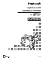
Panasonic AJ-SDC915 Manuale utente
- Categoria
- Videocamere
- Tipo
- Manuale utente
Questo manuale è adatto anche per

AJ-
P
Digital Camera/VTR
Operating Instructions
Model No.
VQT0A45
Printed in Japan
F0802H D
P
Before operating this product, please read the instructions carefully and save this manual for future use.

–2–
For your safety
The lightning flash with arrowhead symbol,
within an equilateral triangle, is intended to alert
the user to the presence of uninsulated “dan-
gerous voltage” within the product’s enclosure
that may be of sufficient magnitude to consti-
tute a risk of electric shock to persons.
The exclamation point within an equilateral tri-
angle is intended to alert the user to the pres-
ence of important operating and maintenance
(service) instructions in the literature accompa-
nying the appliance.
CAUTION:
TO REDUCE THE RISK OF FIRE OR
SHOCK HAZARD AND ANNOYING INTER-
FERENCE, USE THE RECOMMENDED
ACCESSORIES ONLY.
is the safety information.
CAUTION: TO REDUCE THE RISK OF ELECTRIC SHOCK,
DO NOT REMOVE COVER (OR BACK).
NO USER-SERVICEABLE PARTS INSIDE.
REFER SERVICING TO QUALIFIED SERVICE PERSONNEL.
CAUTION
RISK OF ELECTRIC SHOCK
DO NOT OPEN
FCC NOTE:
This device complies with Part 15 of the FCC
Rules. To assure continued compliance follow the
attached installation instructions and do not make
any unauthorized modifications.
This equipment has been tested and found to
comply with the limits for a Class A digital device,
pursuant to Part 15 of the FCC Rules. These limits
are designed to provide reasonable protection
against harmful interference when the equipment
is operated in a commercial environment. This
equipment generates, uses, and can radiate radio
frequency energy and, if not installed and used in
accordance with the instruction manual, may
cause harmful interference to radio communica-
tions. Operation of this equipment in a residential
area is likely to cause harmful interference in
which case the user will be required to correct the
interference at his own expense.
Replace battery with part No. CR2032 only.
Use of another battery may present a risk of fire or
explosion.
Caution—Battery may explode if mistreated.
Do not recharge, disassemble or dispose of in fire.
Ni-Cd
RBRC
RBRC
WARNING:
TO REDUCE THE RISK OF FIRE OR
SHOCK HAZARD, DO NOT EXPOSE THIS
EQUIPMENT TO RAIN OR MOISTURE.
CAUTION:
TO REDUCE THE RISK OF FIRE OR
SHOCK HAZARD, REFER MOUNTING OF
THE OPTIONAL BOARD TO AUTHO-
RIZED SERVICE PERSONNEL.
ATTENTION:
The product you have purchased is powered by a
nickel cadmium battery which is recyclable. At the
end of it’s useful life, under various state and local
laws, it is illegal to dispose of this battery into your
municipal waste stream.
Please call 1-800-8-BATTERY for information on
how to recycle this battery.

– 3 –
Contents
For your safety . . . . . . . . . . . . . . . . . . . 2
General and Features . . . . . . . . . . . . . . 5
ÁFeatures of the Camera Section. . . . . 5
ÁFeatures of the VTR Section . . . . . . . 8
System Configuration . . . . . . . . . . . . . . 9
Controls and Their Functions
ÁPower Supply Section. . . . . . . . . . . . . 10
ÁAccessory Mounting Section . . . . . . . 11
ÁAudio Function Section. . . . . . . . . . . . 12
ÁShooting (Recording)/Playback
Function Section . . . . . . . . . . . . . . . . . 14
ÁMenu Operation Section . . . . . . . . . . . 20
ÁTime Code-Related Section . . . . . . . . 20
ÁWarning/Status Display Section . . . . . 22
Power Supply
ÁUsing an Anton Bauer Battery
Pack . . . . . . . . . . . . . . . . . . . . . . . . . . 23
ÁUsing the BP-90 type Battery Pack. . . 24
ÁUsing a Sony Battery Pack . . . . . . . . . 26
ÁUsing the Sony BP-90 Battery
Pack . . . . . . . . . . . . . . . . . . . . . . . . . . 27
ÁUsing the Sony BP-L60/BP-L90
lithium-ion Battery Pack . . . . . . . . . . . 27
ÁUsing an AC Power Supply (When
Using the AJ-B75 AC Adaptor) . . . . . . 28
ÁChecking and Selecting the Type of
Battery . . . . . . . . . . . . . . . . . . . . . . . . 029
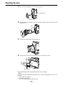
Mounting the Lens . . . . . . . . . . . . . . . 30
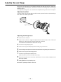
Adjusting the Lens Flange . . . . . . . . . 31
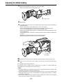
Adjusting the White Shading . . . . . . . 32
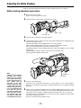
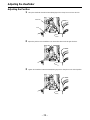
Adjusting the Viewfinder
ÁAdjusting the Position . . . . . . . . . . . . . 34
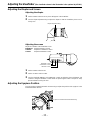
ÁAdjusting the Diopter and
Screen . . . . . . . . . . . . . . . . . . . . . . . . 35
ÁAdjusting the Eyepiece Position . . . . . 35
ÁDetaching the Eyepiece . . . . . . . . . . . 36
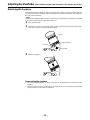
ÁMounting the Viewfinder . . . . . . . . . . . 37
ÁDetaching the Viewfinder . . . . . . . . . . 37
Audio Input Preparations
ÁUsing the Microphone Mounted to the
Main Unit. . . . . . . . . . . . . . . . . . . . . . . 38
ÁUsing the AJ-MC700P Microphone Kit
(Option) Microphone Mounted to the
Main Unit. . . . . . . . . . . . . . . . . . . . . . . 38
ÁMounting the AJ-MH700P Microphone
Holder (Option) . . . . . . . . . . . . . . . . . . 39
Bold letters should be set or adjusted immediately after
purchase.
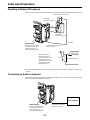
ÁUsing the Microphone not Mounted to
the Main Unit. . . . . . . . . . . . . . . . . . . . 40
ÁMounting a Wireless Microphone . . . . 41
ÁConnecting an Audio Component. . . . 41
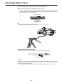
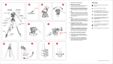
Mounting the Unit to a Tripod . . . . . . . . 42
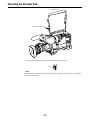
Mounting the Shoulder Belt. . . . . . . . . . 43
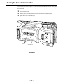
Adjusting the Shoulder Pad Position. . . 44
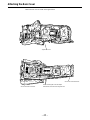
Attaching the Rain Cover . . . . . . . . . . . 45
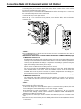
Connecting the AJ-EC3 Extension
Control Unit (Option) . . . . . . . . . . . . . 46
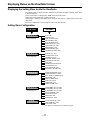
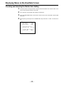
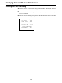
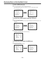
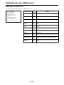
Displaying Menus on the Viewfinder Screen
ÁDisplaying the Setting Menu Inside the
Viewfinder . . . . . . . . . . . . . . . . . . . . . . 47
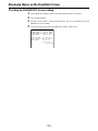
ÁSetting Menu Configuration . . . . . . . . 47
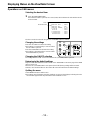
ÁChecking and Selecting the Master Gain
Setting. . . . . . . . . . . . . . . . . . . . . . . . . 48
ÁSelecting the Color Bar Setting. . . . . . 49
ÁChecking the DIAGNOSTIC Screen
Setting. . . . . . . . . . . . . . . . . . . . . . . . . 50
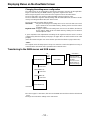
ÁTransferring to the MAIN menus and
SUB menus. . . . . . . . . . . . . . . . . . . . . 51
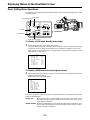
ÁBasic Setting Menu Operations . . . . . 52
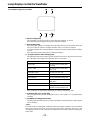
Lamp Displays Inside the
Viewfinder . . . . . . . . . . . . . . . . . . . . . 55
ÁSetting the ! Lamp Display . . . . . . . . . 56
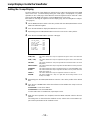
Status Displays Inside the Viewfinder
Screen . . . . . . . . . . . . . . . . . . . . . . . . 57
ÁSelecting Display Items. . . . . . . . . . . . 60
ÁDisplay Mode and Setting Change
Message . . . . . . . . . . . . . . . . . . . . . . . 61
ÁChanging the Display Mode . . . . . . . . 62
ÁSetting the Marker Displays . . . . . . . . 62
ÁSetting the Camera ID . . . . . . . . . . . . 63
Displays
ÁRemaining Battery Level and Audio
Level Displays. . . . . . . . . . . . . . . . . . . 64
ÁVTR Section Operation/Status-Related
Displays . . . . . . . . . . . . . . . . . . . . . . . 64
ÁTime Code-Related Displays . . . . . . . 65
Adjusting the Time and Date. . . . . . . . . 66
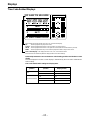
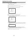
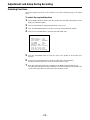
Adjustments and Setup During Recording
ÁAdjustments and Setup Using theSetting
Menu. . . . . . . . . . . . . . . . . . . . . . . . . . 67
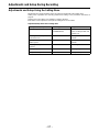
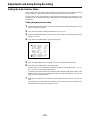
ÁSetting the Gain Selector Value . . . . . 68
ÁSelecting Functions . . . . . . . . . . . . . . 69

– 4 –
Contents
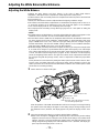
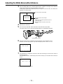
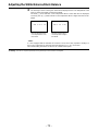
Adjusting the White Balance/Black Balance
ÁAdjusting the White Balance . . . . . . . . 70
ÁAdjusting the Black Balance . . . . . . . . 75
Setting the Electronic Shutter
ÁShutter Modes . . . . . . . . . . . . . . . . . . 77
ÁSetting the Shutter Mode/Speed. . . . . 78
ÁSetting the Synchro Scan Mode . . . . . 79
ÁChanging the Shutter Speed/Mode
Selection Range . . . . . . . . . . . . . . . . . 80
Changing the Iris Automatic Adjustment
Reference Value . . . . . . . . . . . . . . . . 80
Adjusting the Audio Level . . . . . . . . . . . 81
Setting the Time Data
ÁSetting the Time Code . . . . . . . . . . . . 83
ÁSetting the User Bit. . . . . . . . . . . . . . . 84
ÁLocking the Time Code to an External
Source . . . . . . . . . . . . . . . . . . . . . . . . 85
ÁExternal Lock Operation
Procedure . . . . . . . . . . . . . . . . . . . . . . 85
Using the user data . . . . . . . . . . . . . . . . 86
ÁUser data operation . . . . . . . . . . . . . . 86
ÁSaving the user data. . . . . . . . . . . . . . 86
ÁLoading the user data . . . . . . . . . . . . . 86
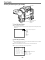
Setup Card Operations
ÁSetup Card Handling . . . . . . . . . . . . . 87
ÁSetup Card Data Operations . . . . . . . 88
Cassettes
ÁInserting and Ejecting Cassettes . . . . 93
ÁPreventing Accidental Erasure . . . . . . 94
Recording
ÁBasic Procedures . . . . . . . . . . . . . . . . 95
ÁSuccessive Shooting . . . . . . . . . . . . . 98
Playback—Checking Recorded Contents
ÁRec Review. . . . . . . . . . . . . . . . . . . . . 100
ÁColor Playback . . . . . . . . . . . . . . . . . . 100
Connection With an External VTR. . . . . 101
Recording Simultaneously with the
Internal VTR and an External
VTR . . . . . . . . . . . . . . . . . . . . . . . . . . 102
Recording With an External VTR Instead
of the Internal VTR
ÁUsing the 26-pin/12-pin Output
Adaptor . . . . . . . . . . . . . . . . . . . . . . . . 104
RET Button . . . . . . . . . . . . . . . . . . . . . . 106
Replacing the Backup Battery. . . . . . . . 107
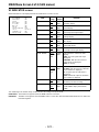
Setting Menu Screens. . . . . . . . . . . . . . 108
ÁMAIN menus . . . . . . . . . . . . . . . . . . . . 108
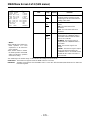
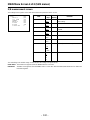
ÁMAIN menu screen 1 of 4
(SUB menus) . . . . . . . . . . . . . . . . . . . 112
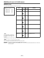
ROP (112), MATRIX (113), LOW SETTING (114), MID
SETTING (115), HIGH SETTING (116), ADDITIONAL DTL
(117), SKIN TONE DTL (118), KNEE/LEVEL (119), FLARE/
GAMMA (120), CAMERA SETTING (120)
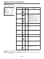
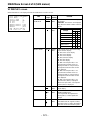
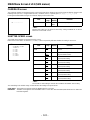
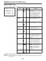
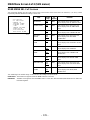
ÁMAIN menu screen 2 of 4
(SUB menus) . . . . . . . . . . . . . . . . . . . 121
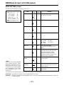
VF DISPLAY (121), VF INDICATOR (123), CAMERA ID
(124), SHUTTER SPEED (124), SYNCHRO SCAN (125),
!LED (125), CAMERA SW MODE (126), SUPER GAIN
(127), VTR FUNCTION (128), BATT/TAPE ALARM (130)
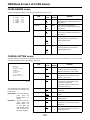
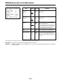
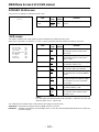
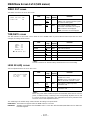
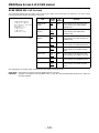
ÁMAIN menu screen 3 of 4
(SUB menus) . . . . . . . . . . . . . . . . . . . 131
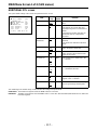
CARD READ/WRITE (131), CARD R/W SELECT (132),
REC (ASPECT)/PB/RET (133), MIC/AUDIO (134),
GENLOCK/IRIS (136), VIDEO OUT (137), TIME/DATE
(137), LENS SEL/ADJ (137)
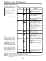
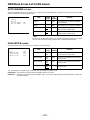
ÁMAIN menu screen 4 of 4
(SUB menus) . . . . . . . . . . . . . . . . . . . 138
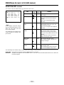
USER MENU SEL 1 of 3 (138), USER MENU SEL 2 of 3
(139), USER MENU SEL 3 of 3 (140), AUTO SHADING
(141), EVALUATION (141), INITIALIZE (146),
DIAGNOSTIC (146)
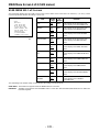
ÁREMOTE menu screen. . . . . . . . . . . . 147
REMOTE FUNCTION (147), VF IND. (REMOTE) (147),
!LED (REMOTE) (148), TALLY/RET (REMOTE) (148)
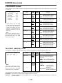
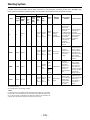
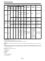
Warning System . . . . . . . . . . . . . . . . . . 149
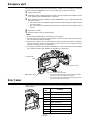
Emergency eject . . . . . . . . . . . . . . . . . . 151
Error Codes. . . . . . . . . . . . . . . . . . . . . . 151
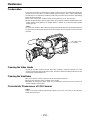
Maintenance
ÁCondensation . . . . . . . . . . . . . . . . . . . 152
ÁCleaning the Video Heads . . . . . . . . . 152
ÁCleaning the Viewfinder . . . . . . . . . . . 152
ÁCharacteristic Phenomenon of CCD
Cameras . . . . . . . . . . . . . . . . . . . . . . . 152
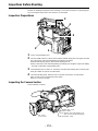
Inspections Before Shooting
ÁInspection Preparations . . . . . . . . . . . 153
ÁInspecting the Camera Section. . . . . . 153
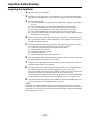
ÁInspecting the Viewfinder . . . . . . . . . . 154
ÁInspecting the Iris and Zoom
Functions . . . . . . . . . . . . . . . . . . . . . . 155
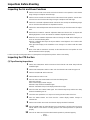
ÁInspecting the VTR Section . . . . . . . . 155
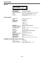
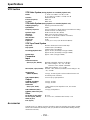
Specifications
ÁGeneral . . . . . . . . . . . . . . . . . . . . . . . . 157
ÁCamera Section . . . . . . . . . . . . . . . . . 157
ÁViewfinder . . . . . . . . . . . . . . . . . . . . . . 157
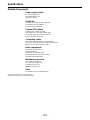
ÁVTR Section . . . . . . . . . . . . . . . . . . . . 158
ÁAccessories . . . . . . . . . . . . . . . . . . . . 158
ÁRelated Components . . . . . . . . . . . . . 159

– 5 –
General and Features
This unit combines as a single integrated unit a 3-CCD color video camera which features IT-
CCDs and a 520,000-pixel on-chip lens, and a DVCPRO format VTR which incorporates com-
pression technology.
Not only can the screen aspect ratio be switched between 16:9 and 4:3 in a single action but the
rate at which the signals are recorded onto the VTR tape can also be set to 50 Mbps for a higher
picture quality or 25 Mbps for a longer recording duration. Recording at the 50 Mbps rate enables
pictures with a very high picture quality to be recorded: this means that this is an integrated VTR
unit which provides all the optimum functions and performance for EFP applications.
The unit in itself is compact and lightweight, its power consumption is minimal, it yields a high
picture quality, and it offers excellent sensitivity, mobility and dust-proof and damp-proof capabili-
ty. These features make it possible for the unit to be used in ENG applications as well.
Both the camera unit and VTR unit feature digital signal processing to achieve much higher levels
of picture quality and stability.
Memory cards complying with global standards can be used for the camera and VTR setting data
to provide a system to manage the data.
Features of the Camera Section
The camera section of the AJ-SDC915 has the following features.
ÁHigh sensitivity: 2000 lux (F13)
ÁHigh S/N ratio: 63 dB (standard)
ÁUltra-low smear
ÁUltra-low flare
Digital signal processing
Signal processing is digitized by a 18 MHz (typ.) 10-bit AD/DA converter. This improves picture
quality, stability and reliability, and allows the viewfinder screen displays as well as numerous
adjustment and setup items to be converted to menus.
Setting menu
The setting menu is displayed on the viewfinder screen, and controls the status displays, messag-
es, marker displays, etc. Whether or not to display each item, as well as the display conditions
when items are to be displayed, can be selected according to the user’s convenience. For exam-
ple, display ON/OFF for the ! lamp display which informs the user that the unit has entered irregu-
lar status can be selected for 8 different conditions.
The setting menu is also used to select various settings and functions and execute memory card
operations, etc.
Setup cards
Setting menu and subject data can be stored on SRAM memory cards with a capacity of 64 kilo-
bytes or greater which conform to PCMCIA standard ratings as setup cards. Stored data can be
saved individually or according to the shooting conditions, allowing the same setup conditions to
be easily reproduced and assisting in standardizing setup conditions between individual data.
An ATA flash memory card with a memory size of 4 MB or more is required to operate the Picture
Link (Pix Link) function sold as an optional accessory.
High-function electronic shutter
Using the built-in electronic shutter achieves steady images even of quickly moving subjects. In
addition, the following special operation modes can also be selected.
ÁSynchro scan mode: This mode is suited for shooting personal computer and workstation moni-
tor screens (60.8–250 Hz), and provides images with little horizontal stripe noise.
ÁHigh vertical resolution (Super V) mode: This mode provides images with high vertical resolution
compared to standard mode.
Wide range of video gain selections
Gain values can be selected from p3 dB to o30 dB using the setting menu and the GAIN switch.
The high S/N ratio allows images with little noise to be obtained even when the gain is increased
for shooting in dark locations. Using the SUPER GAIN switch provided specially to implement the
super gain function, the video gain can be set to 30 or 36 dB.

– 6 –
Features
Automatic adjustment and memory functions for black balance/white balance
The black set, black balance and white balance can be automatically adjusted by simple switch
operations. Adjustment values are held in the memory even if the power for the unit is turned off,
so there is no need to readjust the balance each time the power is turned on.
There are two memory systems for white balance which can hold four adjustment values each for
the CC and ND filters, making a total of eight adjustment values. When adjustment values match-
ing the illumination conditions are selected from among the values stored in the memory, the unit
is automatically adjusted to the corresponding white balance. (A menu setting also allows adjust-
ment of only two values instead of the values for each filter.) In addition, when the unit is shipped
from the factory, the white balance value for 3200K is stored in the memory as a preset value. This
value can be called when there is no time to adjust the white balance, etc.
Character display function
The unit is equipped with a function that displays switch settings, the automatic adjustment status
for black balance and white balance, warning displays, etc. on the viewfinder screen.
In addition, when using an Anton Bauer Digital Magnum series battery as the unit’s power supply,
the remaining battery level can be displayed numerically on the viewfinder screen.
Warning system for displaying the VTR section status
The unit informs of VTR trouble, the end of the tape, battery wear, etc. with various warning lamps
and a warning tone. The remaining tape time can also be checked by the character display inside
the viewfinder.
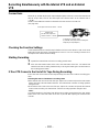
Four filter disks as standard equipment
CC (color temperature conversion) and ND (neutral density) filters are provided as standard
equipment. This allows the optional filter setting to be selected from among four combinations in
accordance with the brightness of the subject.
Fine adjustment of the automatic iris reference value
The reference value for automatic iris adjustment can be finely adjusted by setting menu opera-
tions.
Auto close function
The unit is equipped with an auto close function which automatically closes the lens in the follow-
ing cases.
ÁWhen the black balance is automatically adjusted.
ÁWhen the power is turned off in the auto iris mode.
Generation of SMPTE/SNG color bar and reference audio signals
The camera section contains a circuit which generates an SMPTE type color bar signal to facili-
tate color monitor adjustments, and a circuit which generates a reference level audio signal to
facilitate audio level adjustments.
The unit also contains a circuit for generating SNG color bar signals which come in handy for
sending signals to communication satellites.
Functions and circuits for assuring high picture quality
The AJ-SDC915 is equipped with the following functions (and circuits) in order to assure high
picture quality and is designed to make the fullest use of the advantages of the high-performance
CCD.
ÁA built-in AUTO KNEE circuit achieves a wide dynamic range which allows large signals to pass
through.
ÁA built-in 2-line image enhancer
ÁA built-in shading compensation function for use with a lens extender
ÁA built-in sawtooth wave generator for adjustments
ÁA zebra pattern ON/OFF selector switch which selects three types of zebra patterns including
spot zebra from two levels of zebra patterns.

– 7 –
Features
Audio functions
ÁA phantom power supply type super-cardioid microphone (option) can be attached and it can
also be detached from the main unit for use in interviews.
ÁMicrophone can also be connected, and can be attached to the main unit using the
AJ-MH700P microphone holder (option).
ÁThe audio CH1 recording level can be easily adjusted at the front panel of the unit.
Recording by an external VTR
When an external VTR is connected using the 26-pin/12-pin output adaptor (option,
AJ-YA900P), recording can be performed by the external VTR instead of the internal VTR.
Remote control
Connecting the Extension Control Unit (option, AJ-EC3) allows a portion of the camera section
functions to be operated by remote control.

– 8 –
Features
Features of the VTR Section
Digital system
The VTR section features a component digital recording system that employs the latest compres-
sion technology and non-compressed PCM recording for audio. This system provides superior S/
N, frequency band and waveform characteristics as well as reproduction of detailed areas, etc.,
and realizes even higher picture and sound quality.
One of the following 4 modes can be selected for conducting recording and playback: 16:9
(50 Mbps), 4:3 (50 Mbps), 16:9 (25 Mbps) and 4:3 (25 Mbps).
Rec review function
By automatically rewinding and playing back the last two to ten seconds or so of the recording,
this function enables what has been recorded to be promptly checked out.
Playback function
This function enables the playback picture (black-and-white picture) to be seen on the viewfinder
screen. In addition, color playback pictures can be output from the unit’s VIDEO OUT connector.
Built-in time code generator/reader
Time code information can be recorded and played back on a dedicated subcode track.
Locking of the time code to an external source
The built-in time code generator can be locked to an external generator. Also, the built-in time
code generator uses a lithium battery as its back-up power supply, allowing time codes to be
backed up for approximately one year even if power is not supplied to the unit.
Built-in DOLBY NR SystemF
A Dolby B Noise Reduction System is built in for audio recording in the longitudinal direction.
Successive shooting
Images can be shot successively within an accuracy of 0–o1 frame simply by pressing the VTR
START button or the lens VTR button.
FDolby noise reduction manufactured under license from Dolby Laboratories Licensing Corporation.
“Dolby” and the double-D symbol are trademarks of Dolby Laboratories Licensing Corporation.

– 9 –
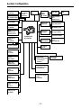
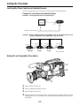
System Configuration
Multi connector
cable
SHAN-C12TCA
Carrying case
AJ-HT900
Microphone kit
AJ-MC700P
Shoulder
belt
Wireless
microphone
receiver
WX-RA700
26P/12P
output
adaptor
AJ-YA900P
VTR cable VTR
Microphone holder
AJ-MH700P
Lens
(Bayonet type)
Fujinon/Canon
Camera/VTR
AJ-SDC915
Battery case
SHAN-B220
Battery case
AU-M402H
Battery case/
Battery holder
AC adaptor
AJ-B75
Sony Battery
BP-90
BP-L60/BP-L90
Sony Battery NP-1
BP-90 type Battery
Anton Bauer Battery
Rain cover
SHAN-RC700
Soft carrying
case
AJ-SC900
Tripot mount
adaptor
SHAN-TM700
Extension control
unit
AJ-EC3
Cleaning tape
AJ-CL12MP
Cassette tape
ÁM size cassette tape
exclusively for
DVCPRO
Setup memory card
SHL-064HSRVS
5w EVF mount
adaptor
AJ-QVF900
5w EVF AJ-VF53P
5w EVF mount
adaptor
AJ-YA711
5w EVF
WV-VF65B/C
Picture Link adaptor
board
AJ-YAP900
1.5½ viewfinder
AJ-VF10P/-VF15P
2.0½ viewfinder
AJ-VF20WP
IDX Battery L-40

– 10 –
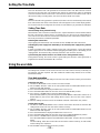
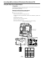
Controls and Their Functions
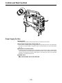
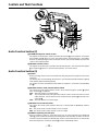
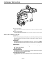
Power Supply Section
e Battery holder
The battery pack (option) made by Anton Bauer is mounted onto this holder.
f DC IN (external power input) connector (XLR, 4P)
The AJ-B75 AC adaptor (option) is plugged into this socket when the unit is to be operated by
AC power. An external battery is plugged in when an external battery is to be used to operate
the unit.
g BREAKER (circuit breaker) button
In order to protect the equipment, the circuit breaker is tripped and the power is automatically
turned off when an excessively high level of power flows inside. Upon completion of the internal
inspection and adjustments, push this button back in. The power will come back on provided
that there is no trouble inside the unit.
h POWER switch
ON: Set to this position to turn on the unit’s power.
OFF: Set to this position to turn off the unit’s power.
3
1
4
2

– 11 –
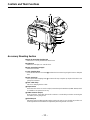
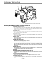
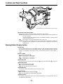
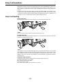
Accessory Mounting Section
i Hook for mounting shoulder belt
Attach the accessory shoulder belt to this hook.
j Light shoe
Mount the video light, etc. onto this shoe.
k Lens mount (bayonet type)
Mount the lens here.
l Lens clamping lever
Insert the lens into the lens mount k, and turn the lens mount ring using this lever to clamp the
lens.
m Lens mount cap
Press up the lens clamping lever l to remove this cap. Keep the cap in place if the lens is not
going to be mounted.
n Lens cable clamp
This is for clamping the lens cable.
o Tripod mount
When the unit is to be secured to a tripod, mount the tripod attachment (SHAN-TM700) which
is available as an optional accessory.
p LENS connector (12-pin)
Hook up the lens connecting cable to this connector. Consult with your dealer concerning the
lens which you are going to use.
q Shoulder pad
Adjust this pad to facilitate operation when carrying the unit on your shoulder. Its position can
be brought forward or backward and adjusted by loosening the two set screws.
7
9
n
5
q
p
5
o
6
8
Controls and Their Functions

– 12 –
Controls and Their Functions
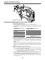
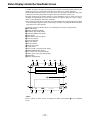
Audio Function Section (1)
r AUDIO LEVEL CH1 (audio channel 1 recording level) control
When the AUDIO SELECT CH1/CH2 switch u is set to MAN, the recording level of audio
channel 1 can be adjusted by this control in addition to the AUDIO LEVEL CH1 control t on
the side panel.
s MIC IN (microphone input) jack (XLR, 3-pin)
Connect an optional microphone to this jack. The power for the microphone is supplied from
this jack.
t AUDIO LEVEL CH1/CH2 (audio channel 1/2 recording level) controls
When the AUDIO SELECT CH1/CH2 switch u is set to MAN, the audio level of audio channels
1 and 2 can be adjusted using these controls.
However, the audio CH1 level can also be adjusted using the AUDIO LEVEL CH1 control r on
the front panel.
u AUDIO SELECT CH1/CH2 switch (audio channel 1/2 auto/manual level adjustment selec-
tor) switch
This selects the method used to adjust the audio levels of audio channels 1 and 2.
AUTO: For adjusting the levels automatically.
MAN: For adjusting the levels manually.
v AUDIO IN (audio input selector) switch
This selects the input signals to be recorded on audio channels 1 and 2.
FRONT [MIC]: The microphone input signals connected to the MIC IN jack s are recorded.
REAR [MIC]: The microphone input signals connected to the AUDIO IN CH1/CH2 connec-
tors y are recorded.
REAR [LINE]: The line input signals connected to the AUDIO IN CH1/CH2 connectors y
are recorded.
w REAR MIC POWER switch
ON: The phantom power is supplied to the rear microphone.
OFF: The phantom power is not supplied to the rear microphone.
x CUE switch
CH1: The audio CH1 signals are recorded on the cue track.
1/2: The signals of audio CH1 and CH2 are mixed together and recorded on the cue track.
CH2: The audio CH2 signals are recorded on the cue track.
y AUDIO IN CH1/CH2 (audio input channel 1/2) connectors (XLR, 3P)
An audio component or microphone is connected here.
z AUDIO OUT connector (XLR, 3P)
This is connected to an audio component. The audio channels are coupled to the MONITOR
SELECT switch and switched in tandem.
{ DC OUT (DC power output) connector
This is the DC 12 V output connector. A current of approximately 100 mA can be taken out.
s
r
The accessory
control knob can be
attached to the
AUDIO LEVEL CH1
control.
Knob
(included)
Screw
(included)

– 13 –
Audio Function Section (2)
| ALARM (warning tone volume) control
This adjusts the warning tone volume heard from the speaker ~ or the earphone connected to
the PHONES jack ¡. When it is set to the lowest position, the warning tone is not audible.
However, by making changes to the inside parts, the tone can be made audible even when the
control is at its lowest position.
} MONITOR (volume) control
This adjusts the volume of the sound other than the warning tone—the sound from the speaker
~ or earphone ¡. When it is set to the lowest position, no sound is heard.
Audio Function Section (3)
~ Speaker
During recording, the EE sound can be monitored; during playback, the playback sound can be
monitored.
The warning tone is heard through the speaker in synchronization with the flashing or lighting
of the warning lamp and warning display.
The speaker sound is automatically muted when an earphone is connected to the PHONES
jack ¡.
MONITOR SELECT (audio channel selector) switch
This selects the audio channel whose sound is to be heard through the speaker ~ AUDIO
OUT connector z, or earphone.
CH1: The audio channel 1 sound is output.
1/2: The sound produced by mixing the audio channel 1 and 2 sound or the stereo sound is
output. However, only the mixed sound is output from the speaker ~ and AUDIO OUT
connector z.
CH2: The audio channel 2 sound is output.
MONITOR (sound selector) switch
This selects the sound of the earphone when 1/2 is selected with the MONITOR SELECT
switch .
ST: The stereo sound of audio channels 1 and 2 is output.
MIX: The mixed sound of audio channels 1 and 2 is output.
¡ PHONES (earphone) jack (mini-jack)
When an earphone (option) is connected to this jack, the sound selected by the MONITOR
switch can be heard. The warning tones relating to the unit’s operation or status can also be
heard. An earphone enabling a sufficiently high volume of sound to be heard is recommended.
When the earphone is connected, speaker ~ sound is automatically muted.
|
}
~
t
u
v
x
{
°
y
w
†
z
°
Controls and Their Functions

– 14 –
Controls and Their Functions
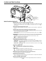
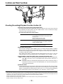
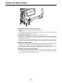
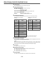
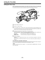
Shooting (Recording)/Playback Function Section (1)
¢ Viewfinder (optional accessory)
Black-and-white images can be seen in the viewfinder during recording and playback. Warn-
ings and messages relating to the unit’s operating status and settings, zebra pattern, markers
(safety zone marker, center marker), etc. can also be seen.
£ PEAKING control
This is used to adjust the contours of the images inside the viewfinder to facilitate focusing. It
does not affect the camera’s output signals.
¤ CONTRAST control
This is used to adjust the contrast of the screen inside the viewfinder. It does not affect the
camera’s output signals.
¥ BRIGHT control
This is used to adjust the brightness of the screen inside the viewfinder. It does not affect the
camera’s output signals.
¦ ZEBRA (zebra pattern) switch
This displays the zebra pattern inside the viewfinder.
ON: The zebra pattern is displayed.
OFF: The zebra pattern is not displayed.
When the unit is shipped from the factory, the zebra pattern is set in such a way that those
parts with an IRE video level from approx. 70% to 85% are displayed. The displaying of parts
with a level ranging from 50% to 110% or more or with a certain level can also be set on the
setting menu.
§ Diopter control knob
This is adjusted in such a way that the images on the viewfinder screen are seen most clearly
in accordance with the dioptric power of the camera’s operator.
¨ Eyepiece
© Viewfinder forward-backward/left-right position clamp lever
Loosen this lever to adjust the position of the viewfinder ¢ in the forward-backward or left-right
direction.
ª Eyepiece forward-backward movement ring
Turn this ring to adjust the position of the eyepiece ¨ in the forward-backward direction.
« Viewfinder stopper screw
To detach the viewfinder ¢ from the camera, loosen this screw and then detach the view-
finder.
£
§
•
¶
¢
©
(The viewfinder shown in the illustration is the AJ-VF10P.)

– 15 –
Æ
ß
¨
™
®
≠
´
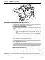
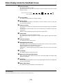
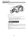
Shooting (Recording)/Playback Function Section (2)
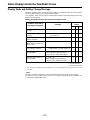
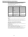
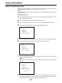
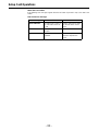
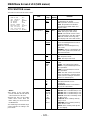
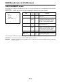
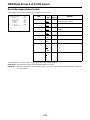
¬ CC/ND FILTER (filter selector) knob
This selects the filter to match the light source which is illuminating the subject.
If the setting of this knob is changed when the menu display mode has been set to “3” (default
setting), the new setting will appear on the setting change message display area of the view-
finder screen.
(The viewfinder shown in the
illustration is the AJ-VF10P.)
Controls and Their Functions
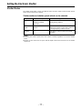
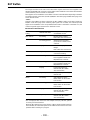
È The knob and filter settings are
listed below.
FILTER
Description
knob setting
1 3200 K
2 5600 Ko1/8ND
3 5600 K
4 5600 Ko1/64ND
È Examples of filter settings to match
shooting conditions
Filter Shooting condition
1 Sunrise, sunset, inside a studio
2 Outdoors under a clear sky
3 Outdoors under a cloudy or rainy sky
4 Snow scenes, high mountains,
coastlines and other extremely clear
and bright scenes
Synchro scan adjustment switches
These switches are used to adjust the synchro scan speed. Pressing the “p” switch reduces
the shutter speed; pressing the “o” switch increases the shutter speed. Set these switches to a
position where the side bar noise in the viewfinder is eliminated during personal computer
monitor shooting, etc.
|Note{
When these switches are used for UB/TC/CTL settings while the SET position has been select-
ed as the TCG switch position, they will not serve their function as synchro scan adjustment
switches. The TCG switch must be set to F-RUN or R-RUN for these switches to serve their
function.
® WHITE BAL (white balance memory selector) switch
PRST: Set to this position when there is no time to adjust the white balance. The white bal-
ance value for 3200K is stored in the memory.
A or B: When the AUTO W/B BAL switch ± is pressed to the AWB side, the white balance
is automatically adjusted in accordance with the setting position of the filter knob ¬,
and the adjustment value is stored in memory A or memory B.
When the FILTER knob and the WHITE BAL switch are set to the same positions as the ones
set when the adjustment was made, the adjustment value stored in the memory is called, and
the unit is automatically adjusted to the white balance which corresponds to this value.
If the setting of this switch is changed when the menu display mode has been set to “3” (default
setting), the new setting will appear at the WHITE BAL switch display position on the viewfinder
screen. (Example: “A”)

– 16 –
Controls and Their Functions
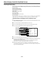
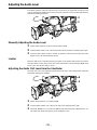
Shooting (Recording)/Playback Function Section (3)
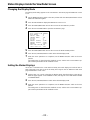
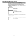
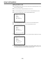
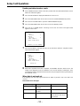
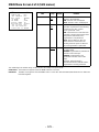
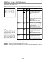
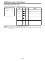
¯ OUTPUT (output signal selector)/AUTO KNEE switch
This switch selects the video signals which are to be output from the camera unit to the VTR
unit, viewfinder and video monitor. The AUTO KNEE function can be used when the images
shot by the camera have been selected.
È OUTPUT/AUTO KNEE switch setting positions
BARS Color bar signals are output. The AUTO KNEE circuit
is not activated. Set the switch to this position in the
following cases:
ÁWhen adjusting the video monitor
ÁWhen recording color bar signals
CAM, AUTO KNEE OFF The images shot by the camera are output.
The AUTO KNEE circuit is not activated. The default
setting is “MANUAL KNEE”.
CAM, AUTO KNEE ON The images shot by the camera are output.
The AUTO KNEE circuit is activated.
° GAIN (gain selector) switch
This is used to change the video amplifier’s gain in accordance with the lighting conditions
during shooting. The gain values corresponding to the L, M and H settings are assigned be-
forehand on the setting menu. When the unit is shipped from the factory, these settings are:
Lr0 dB, Mr9 dB and Hr18 dB.
If the setting of this switch is changed when the display mode has been set to “3”, the new
setting will appear at the gain display position on the viewfinder screen. (Example: “12 dB”)
± AUTO W/B BAL (white balance/black balance automatic adjustment) switch
AWB: Set to this position for automatically adjusting the white balance. When the WHITE BAL
switch ® is now set to “A or B”, the adjusted value will be stored in memory A or
memory B.
ABB: Set to this position for automatically adjusting the black balance. When this switch is
held down for at least 10 seconds at the ABB position, the auto black shading will be
compensated automatically.
² SHUTTER switch
Set this to ON when using the electronic shutter. When it is pressed to the SEL side, the shutter
speed and mode displays change in the ranges preset on the setting menu. If the setting of this
switch is changed when the display mode has been set to “2” or “3”, the new setting will appear
at the shutter display position on the viewfinder screen. (Example: “:1/250”, “:1/60.8”)
1) AUTO KNEE function
When the level is adjusted to people, scenes, etc. for shooting against a very bright background, the background will be whited out and the
buildings or scenes in the background will become blurred. If the AUTO KNEE function is activated in cases like these, the background can be
reproduced in clear detail. This function is especially effective for shooting in the following conditions:
ÁWhen shooting people in shade under a clear sky
ÁWhen simultaneously shooting people in vehicles or indoor and the outdoor scenery seen through the windows
ÁWhen shooting scenes with a high contrast
≤
±
∞
Ø
≥

– 17 –
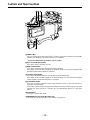
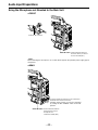
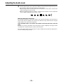
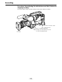
³ ECU REMOTE (remote control) connector (6-pin)
Connect the AJ-EC3 extension control unit (option) here.
|Note{
The POWER switches on unit and extension control unit must be set to OFF before the remote
control cable is connected or disconnected.
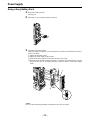
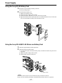
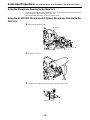
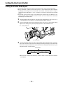
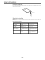
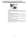
´ 26-pin/12-pin output adaptor (See page 104 for mounting method.)
The 26-pin/12-pin output adaptor AJ-YA900P (option) is mounted on this section. When the
portable VTR is connected as the external VTR, recording can be performed simultaneously
with the unit’s built-in VTR.
Furthermore, by connecting the SHAN-C12TCA multi-connector cable (optional accessory) to
the 12-pin connector, it is possible to output the sound of audio channels 1 and 2 separately.
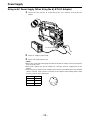
µ VIDEO OUT connector (BNC)
This outputs the video signals (75° termination, rated level) to be monitored. During recording,
EE images can be monitored; during playback, playback images can be monitored.
While performing settings on the menu, the setting menu can be superimposed onto the shot
images appearing on the monitor screen so that the settings can also be checked.
¶ CAM OUT (camera output) connector (BNC)
This outputs the composite video signals (75° termination, rated level). When a video monitor
is connected, the images shot by the camera can be monitored. Even while the VTR is playing
back, the camera’s images are output at all times.
µ
¥
∂
Controls and Their Functions

– 18 –
Controls and Their Functions
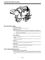
Shooting (Recording)/Playback Function Section (4)
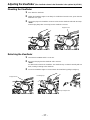
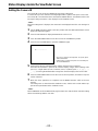
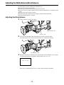
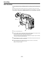
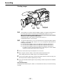
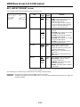
· VTR START button
When this pressed, recording commences; when it is pressed again, recording stops. This
button has the same function as the VTR button on the lens side.
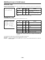
¸ VTR SAVE/STBY (tape protection) switch
This selects the power supply status while the VTR recording is temporarily stopped (REC
PAUSE).
SAVE: This is the tape protection mode. The cylinder is stopped in the half-loading status.
Compared with the STBY position, less power is consumed and the unit can be
operated longer using the battery. It takes longer for recording to commence after
the VTR START button · is pressed in the SAVE position than in the STBY po-
sition.
When the switch is set to this position, the VTR SAVE lamp inside the viewfinder
lights.
STBY: Recording commences immediately when the VTR START button is pressed.
|Note{
This unit will automatically go into SAVE mode when the designated time for standby (STBY)
condition is exceeded. To return to standby mode, press the VTR SAVE/STBY switch once to
select SAVE mode, then once again to return to STBY mode.
¹ MODE CHECK button
While this button is kept depressed, the camera’s setting status is displayed in the viewfinder. It
does not affect the camera’s output signals.
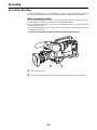
º SUPER GAIN button (inside sliding cover)
The super gain mode is forcibly established when this button is pressed, and each time the
button is pressed when all the super gain values have been set using “SUPER GAIN” on the
MAIN menu 2 of 4 screen, the gain is switched by one level in the following sequence: 30 dB>
36 dB>OFF>30 dB, etc. However, the DTL and other menu settings cannot be performed.
» SUPER IRIS button (inside sliding cover)
This is used when backlight compensation (or the super black functionF
1
) is to be provided.
When it is pressed, the switch settings are displayed inside the viewfinder for 3 seconds. When
it is pressed again, backlight compensation (or the super black functionF
1
) is released.
F
1
See Main Menu Screen 2 of 4 on page 126 for details on the super black function.
Super gain: When 30 dB is allotted to the SUPER IRIS button, DTL and other menu settings cannot be performed for this
30 dB.
∑
º
π
∫
∏
ª

– 19 –
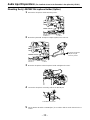
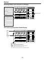
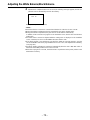
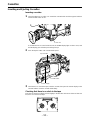
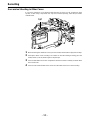
¼ MARK button
This is used when the Picture Link (Pix Link)F
1
function is to be used. Each time it is pressed M1
(MARK1), M2 (MARK2) or no display appears in the viewfinder.
F
1
Picture Link adaptor board (AJ-YAP900) is sold as an option.
½ EJECT (cassette eject) button
Press this to insert or eject the cassette.
¾ REW (rewind) button
Press this to rewind the tape. Its lamp lights during rewinding.
If this button is pressed during playback, the playback images are rewound at approximately
quadruple speed while the button is held down.
¿ FF (fast forward) button
Press this to fast forward the tape. Its lamp lights during fast forwarding.
If this button is pressed during playback, the playback images are fast forwarded at approxi-
mately quadruple speed while the button is held down.
À PLAY/PAUSE button
Press this to view the playback images on the viewfinder screen or color video monitor. Its
lamp lights during playback.
If this button is pressed again during playback, playback is paused and the lamp goes off. After
playback has been paused for 2 minutes, the unit automatically switches to stop status
(STOP).
Á STOP button
Press this to stop the tape travel.
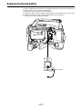
 EMERGENCY screw (inside the rubber cap)
For details, refer to the “emergency eject” function (on page 151).
ø
æ
Ω¿¡
¬
Controls and Their Functions

– 20 –
Controls and Their Functions
Menu Operation Section
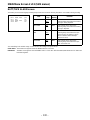
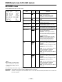
à Setup card insertion slot
The optional setup cards are inserted into this slot.
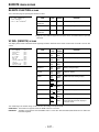
Ä MENU SET/OFF switch
This displays the setting menu on the viewfinder screen through VIDEO OUT connector.
SET: The page on which the previous setting menu operations were completed appears on
the viewfinder screen. (When the menu is used for the first time, the first of the pages
which can be displayed appears.)
OFF: The setting menu is not displayed on the viewfinder screen through VIDEO OUT con-
nector.
Å SHIFT/ITEM button
Each time this button is pressed, the cursor moves on the setting menu page now displayed.
Use it when selecting items.
|Note{
This switch functions differently depending on the operation item. Check the function by oper-
ating the menu item by item.
Æ UP button
This is used to increment the setting of the item selected on the setting menu by 1 level each
time it is pressed or to switch the setting between ON and OFF.
Ç DOWN button
This is used to decrement the setting of the item selected on the setting menu by 1 level each
time it is pressed or to switch the setting between ON and OFF.
È PAGE button
This is used to select the setting menu page.
Time Code-Related Section (1)
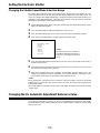
É GENLOCK IN/(VIDEO IN) connector (BNC)
The reference signal is supplied to this connector when the camera section is to be subject to
genlock operation or when the time code is to be locked externally. This connector serves as
an external video input connector when REC SIGNAL: VIDEO has been selected on the setting
menu.
»
√
≈
ƒ
Ã
Õ
(
)
∆
(
)
«
(
)
–œœ
Œ
La pagina sta caricando ...
La pagina sta caricando ...
La pagina sta caricando ...
La pagina sta caricando ...
La pagina sta caricando ...
La pagina sta caricando ...
La pagina sta caricando ...
La pagina sta caricando ...
La pagina sta caricando ...
La pagina sta caricando ...
La pagina sta caricando ...
La pagina sta caricando ...
La pagina sta caricando ...
La pagina sta caricando ...
La pagina sta caricando ...
La pagina sta caricando ...
La pagina sta caricando ...
La pagina sta caricando ...
La pagina sta caricando ...
La pagina sta caricando ...
La pagina sta caricando ...
La pagina sta caricando ...
La pagina sta caricando ...
La pagina sta caricando ...
La pagina sta caricando ...
La pagina sta caricando ...
La pagina sta caricando ...
La pagina sta caricando ...
La pagina sta caricando ...
La pagina sta caricando ...
La pagina sta caricando ...
La pagina sta caricando ...
La pagina sta caricando ...
La pagina sta caricando ...
La pagina sta caricando ...
La pagina sta caricando ...
La pagina sta caricando ...
La pagina sta caricando ...
La pagina sta caricando ...
La pagina sta caricando ...
La pagina sta caricando ...
La pagina sta caricando ...
La pagina sta caricando ...
La pagina sta caricando ...
La pagina sta caricando ...
La pagina sta caricando ...
La pagina sta caricando ...
La pagina sta caricando ...
La pagina sta caricando ...
La pagina sta caricando ...
La pagina sta caricando ...
La pagina sta caricando ...
La pagina sta caricando ...
La pagina sta caricando ...
La pagina sta caricando ...
La pagina sta caricando ...
La pagina sta caricando ...
La pagina sta caricando ...
La pagina sta caricando ...
La pagina sta caricando ...
La pagina sta caricando ...
La pagina sta caricando ...
La pagina sta caricando ...
La pagina sta caricando ...
La pagina sta caricando ...
La pagina sta caricando ...
La pagina sta caricando ...
La pagina sta caricando ...
La pagina sta caricando ...
La pagina sta caricando ...
La pagina sta caricando ...
La pagina sta caricando ...
La pagina sta caricando ...
La pagina sta caricando ...
La pagina sta caricando ...
La pagina sta caricando ...
La pagina sta caricando ...
La pagina sta caricando ...
La pagina sta caricando ...
La pagina sta caricando ...
La pagina sta caricando ...
La pagina sta caricando ...
La pagina sta caricando ...
La pagina sta caricando ...
La pagina sta caricando ...
La pagina sta caricando ...
La pagina sta caricando ...
La pagina sta caricando ...
La pagina sta caricando ...
La pagina sta caricando ...
La pagina sta caricando ...
La pagina sta caricando ...
La pagina sta caricando ...
La pagina sta caricando ...
La pagina sta caricando ...
La pagina sta caricando ...
La pagina sta caricando ...
La pagina sta caricando ...
La pagina sta caricando ...
La pagina sta caricando ...
La pagina sta caricando ...
La pagina sta caricando ...
La pagina sta caricando ...
La pagina sta caricando ...
La pagina sta caricando ...
La pagina sta caricando ...
La pagina sta caricando ...
La pagina sta caricando ...
La pagina sta caricando ...
La pagina sta caricando ...
La pagina sta caricando ...
La pagina sta caricando ...
La pagina sta caricando ...
La pagina sta caricando ...
La pagina sta caricando ...
La pagina sta caricando ...
La pagina sta caricando ...
La pagina sta caricando ...
La pagina sta caricando ...
La pagina sta caricando ...
La pagina sta caricando ...
La pagina sta caricando ...
La pagina sta caricando ...
La pagina sta caricando ...
La pagina sta caricando ...
La pagina sta caricando ...
La pagina sta caricando ...
La pagina sta caricando ...
La pagina sta caricando ...
La pagina sta caricando ...
La pagina sta caricando ...
La pagina sta caricando ...
La pagina sta caricando ...
La pagina sta caricando ...
La pagina sta caricando ...
La pagina sta caricando ...
La pagina sta caricando ...
La pagina sta caricando ...
La pagina sta caricando ...
La pagina sta caricando ...
-
 1
1
-
 2
2
-
 3
3
-
 4
4
-
 5
5
-
 6
6
-
 7
7
-
 8
8
-
 9
9
-
 10
10
-
 11
11
-
 12
12
-
 13
13
-
 14
14
-
 15
15
-
 16
16
-
 17
17
-
 18
18
-
 19
19
-
 20
20
-
 21
21
-
 22
22
-
 23
23
-
 24
24
-
 25
25
-
 26
26
-
 27
27
-
 28
28
-
 29
29
-
 30
30
-
 31
31
-
 32
32
-
 33
33
-
 34
34
-
 35
35
-
 36
36
-
 37
37
-
 38
38
-
 39
39
-
 40
40
-
 41
41
-
 42
42
-
 43
43
-
 44
44
-
 45
45
-
 46
46
-
 47
47
-
 48
48
-
 49
49
-
 50
50
-
 51
51
-
 52
52
-
 53
53
-
 54
54
-
 55
55
-
 56
56
-
 57
57
-
 58
58
-
 59
59
-
 60
60
-
 61
61
-
 62
62
-
 63
63
-
 64
64
-
 65
65
-
 66
66
-
 67
67
-
 68
68
-
 69
69
-
 70
70
-
 71
71
-
 72
72
-
 73
73
-
 74
74
-
 75
75
-
 76
76
-
 77
77
-
 78
78
-
 79
79
-
 80
80
-
 81
81
-
 82
82
-
 83
83
-
 84
84
-
 85
85
-
 86
86
-
 87
87
-
 88
88
-
 89
89
-
 90
90
-
 91
91
-
 92
92
-
 93
93
-
 94
94
-
 95
95
-
 96
96
-
 97
97
-
 98
98
-
 99
99
-
 100
100
-
 101
101
-
 102
102
-
 103
103
-
 104
104
-
 105
105
-
 106
106
-
 107
107
-
 108
108
-
 109
109
-
 110
110
-
 111
111
-
 112
112
-
 113
113
-
 114
114
-
 115
115
-
 116
116
-
 117
117
-
 118
118
-
 119
119
-
 120
120
-
 121
121
-
 122
122
-
 123
123
-
 124
124
-
 125
125
-
 126
126
-
 127
127
-
 128
128
-
 129
129
-
 130
130
-
 131
131
-
 132
132
-
 133
133
-
 134
134
-
 135
135
-
 136
136
-
 137
137
-
 138
138
-
 139
139
-
 140
140
-
 141
141
-
 142
142
-
 143
143
-
 144
144
-
 145
145
-
 146
146
-
 147
147
-
 148
148
-
 149
149
-
 150
150
-
 151
151
-
 152
152
-
 153
153
-
 154
154
-
 155
155
-
 156
156
-
 157
157
-
 158
158
-
 159
159
-
 160
160


Panasonic AJ-SDC915 Manuale utente
- Categoria
- Videocamere
- Tipo
- Manuale utente
- Questo manuale è adatto anche per
in altre lingue
- English: Panasonic AJ-SDC915 User manual
Documenti correlati
-
Panasonic AG6124B Istruzioni per l'uso
-
-
-
-
-
-
Panasonic AK-HRP200G Operating Instructions Manual
-
Altri documenti
-
Sony CCD-FX510 Manuale utente
-
Canon EOS C300 Mark III Manuale utente
-
-
Canon EOS C200 Manuale utente
-
-
Canon EOS C300 Mark II Manuale del proprietario
-
-
Canon EOS C300 Mark II PL Manuale utente
-
Canon XF705 Manuale utente
-
 KINGJOY VT-1200 Manuale utente
