
1
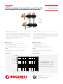
Collettore modulare in tecnopolimero con mis. di portata
Modular manifold in technopolymer, with fl ow meters
R553FP Istruzioni / Instruction
047U58968 04/2022
Collettore modulare premontato per impianti di climatizzazione, in
tecnopolimero, composto da:
• 1 collettore di mandata con misuratori di portata (doppia scala: 0÷5 l/min e
0÷1,5 GPM) con funzione di regolazione/intercettazione del fl uido;
• 1 collettore di ritorno con valvole di intercettazione con volantino manuale
(attacco M30 x 1,5 mm), predisposte per comando elettrotermico mediante
gli attuatori R473, R473M, installabili previo montaggio dell’apposita ghiera
R453FY002 (compresa nella confezione) sul modulo;
• 2 valvole multifunzione R269T (mandata e ritorno);
• supporti R588FP.
Pre-assembled modular manifold for HVAC systems, made of technopolymer,
composed of:
• 1 delivery manifold with fl ow meters (double scale: 0÷5 l/min and 0÷1,5 GPM)
with fl uid adjustment/shut-off function;
• 1 return manifold with shut-off valves with manual handwheel (connection
M30 x 1,5 mm), pre-arranged for thermo-electric command via R473/R473M
actuators that can be installed after fi tting the relative ring nut R453FY002
(included with the kit) on the module;
• 2 multi-function valves R269T (delivery and return);
• brackets R588FP.
Giacomini S.p.A.
Via per Alzo 39, 28017 San Maurizio d’Opaglio (NO) Italia
consulenza.prodotti@giacomini.com
+39 0322 923372 - giacomini.com
Dati tecnici
• Fluidi di impiego: acqua, soluzioni glicolate (max. 30 %)
• Campo di temperatura: 5÷60 °C
• Pressione massima di esercizio: 6 bar (10 bar per collaudo impianto)
• Interasse tra gli stacchi: 50 mm
• Misuratori di portata con doppia scala (0÷5 l/min e 0÷1,5 GPM)
Materiali
• Collettori: struttura interna ed esterna in tecnopolimero
• Valvole multifunzione R269T: ottone UNI EN 12165 CW617N
• Guarnizioni: EPDM
Technical data
• Fluids: water, glycol solutions (max. 30 %)
• Temperature range: 5÷60°C
• Max. operating pressure: 6 bar (10 bar for system testing)
• Center distance between the outlets: 50 mm
• Flow meters with double scale (0÷5 l/min and 0÷1,5 GPM)
Materials
• Manifolds: internal and external structure in technopolymer
• Multi-function valves R269T: brass UNI EN 12165 CW617N
• Gaskets: EPDM
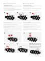
Perdite di carico Losses of pressure
10 100100 1000
Q [l/h]
100
1000
10000
ůp [mm H2O]
1,0
10,0
100
ůp [KPa]
0,01
0,1
1,0
ůp [bar]
F.O.
N° giri ghiera flussimetro
No. of turns flow meter ring nut
T.A.
F.O.
Kv 1,05
R73FPY001
OPTIONAL

2
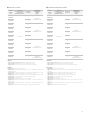
Versioni e codici
CODICE
PRODUCT
CODE
ATTACCHI
COLLETTORE x STACCHI
CONNECTIONS
MANIFOLD x OUTLETS
N° STACCHI
N° OUTLETS
CASSETTA DI
CONTENIMENTO
CABINET
R500-2
R553FP302
G 1” x 3/4”E
2
R500Y221
400x650x85÷130 mm
R553FP303 3
R553FP304 4
R500Y222
600x650x85÷130 mm
R553FP305 5
R553FP306 6
R553FP307 7
R553FP308 8
R500Y223
800x650x85÷130 mm
R553FP309 9
R553FP310 10
R553FP311 11
R553FP312 12 R500Y224
1000x650x85÷130 mm
Ricambi
• R588FPY001: supporto con collarini
• R453FY002: ghiera in plastica M30 x 1,5 mm per installazione delle teste
elettrotermiche
• P553FPY011: modulo di mandata con misuratore di portata e stacco 3/4”E
• P553FPY012: modulo di ritorno con valvola e stacco 3/4”E
• P553FPY013: modulo di mandata con misuratore di portata e stacco B.18
• P553FPY014: modulo di ritorno con valvola e stacco B.18
• P553FPY005: modulo tappo
• P553FPY006: modulo di ingresso (senza calotta)
• P553FPY030: confezione modulo di mandata + modulo di ritorno con
stacchi 3/4”E
• P553FPY031: confezione modulo di mandata + modulo di ritorno con
stacchi B.18
• P583Y004: calotta per modulo di ingresso e guarnizione di tenuta
Optional
• R500-1, R500-2, R500-2E: cassetta metallica da incasso
• R473, R473M: testa elettrotermica normalmente chiusa
• R73FPY001: coppia di chiavi per rimozione moduli collettori
CODICE
PRODUCT
CODE
ATTACCHI
COLLETTORE x STACCHI
CONNECTIONS
MANIFOLD x OUTLETS
N° STACCHI
N° OUTLETS
CASSETTA DI
CONTENIMENTO
CABINET
R500-2
R553FP322
G 1” x Base 18
2
R500Y221
400x650x85÷130 mm
R553FP323 3
R553FP324 4
R500Y222
600x650x85÷130 mm
R553FP325 5
R553FP326 6
R553FP327 7
R553FP328 8
R500Y223
800x650x85÷130 mm
R553FP329 9
R553FP330 10
R553FP331 11
R553FP332 12 R500Y224
1000x650x85÷130 mm
Versions and product codes
Optionals
• R500-1, R500-2, R500-2E: fl ush-mounting metal cabinet
• R473, R473M: normally closed thermo-electric actuator
• R73FPY001: pair of spanners for removing the manifold modules
Spare parts
• R588FPY001: bracket with supports
• R453FY002: plastic ring nut M30 x 1,5 mm for installing the thermo-electric
actuators
• P553FPY011: delivery module with fl ow meter and 3/4”E outlet
• P553FPY012: return module with valve and 3/4”E outlet
• P553FPY013: delivery module with fl ow meter and B.18 outlet
• P553FPY014: return module with valve and B.18 outlet
• P553FPY005: cap module
• P553FPY006: inlet module (without nut)
• P553FPY030: kit composed of delivery module + return module with 3/4”E
outlets
• P553FPY031: kit composed of delivery module + return module with B.18
outlets
• P583Y004: nut and gasket for inlet module

3
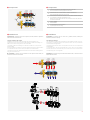
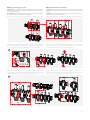
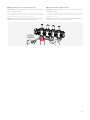
Componenti Components
1Collettore di mandata con stacchi dotati di misuratori di portata
Delivery manifold with outlets equipped with flow meters
2Collettore di ritorno con stacchi dotati di valvola di intercettazione
Return manifold with outlets with a shut-off valve
3
Valvole multifunzione dotate di rubinetto di scarico, valvola automatica di sfogo
aria, termometro e valvola di intercettazione a sfera
Multifunction valves equipped with drain cock, automatic air vent valve, thermome-
ter and shut-off ball valve
4Supporti R588FP
Brackets R588FP
5Clip per fi ssaggio raccordo eccentrico
Clip for fi xing the eccentric fi tting
4
1
2
3
5
5
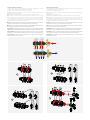
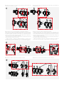
Installation Installazione
Max. 25 Nm
5 Nm
15 Nm
AVVERTENZA. L’installazione deve essere eseguita da personale qualifi cato e seguendo le
istruzioni contenute nella confezione.
Ingresso tubazioni da sinistra
Il collettore viene fornito preassemblato sulle zanche R588FP, con
predisposizione per la connessione delle valvole multifunzione R269T con
attacco da sinistra (confi gurazione raccomandata).
Le valvole multifunzione R269T sono fornite in scatole con i componenti
disassemblati.
Per assemblarle è necessario montare la valvola di sfogo aria, il termometro
e il rubinetto di scarico sul raccordo principale e successivamente
connettere il gruppo al collettore di distribuzione tramite la calotta girevole
e la guarnizione di tenuta.
AVVERTENZA. Il collettore può essere installato solo sulle apposite zanche R588FP, non
sostituire mai tali zanche con altri modelli.
WARNING The installation must be carried out by qualifi ed personnel, following the
instructions provided in the package.
Pipe inlet from the left
The manifold is supplied pre-assembled on the R588FP brackets, and pre-
arranged for connecting R269T multi-function valves with left connection
(recommended confi guration).
The R269T multi-function valves are supplied in boxes, with the components
disassembled.
To assemble them, fi rst of all assemble the air vent valve, the thermometer
and the drain cock on the main body, then connect the unit to the distribution
manifold using the nut and gasket.
WARNING The manifold can only be installed on the R588FP brackets, so these must never be
replaced with other models.

4
Max. 25 Nm 5 Nm
15 Nm
4
3
AVVERTENZA. Nell’installazione con ingresso tubazioni da destra, le clips degli adattatori
(componenti - rif.5) non risulteranno accessibili, poichè saranno rivolte verso l’interno della cassetta.
AVVERTENZA. Il collettore può essere installato solo sulle apposite zanche R588FP, non
sostituire mai tali zanche con altri modelli.
AVVERTENZA. Nell’installazione con ingresso tubazioni da destra, il termometro delle valvole
multifunzione R269T viene montato nella parte inferiore del raccordo principale, come illustrato in fi gura.
Ingresso tubazioni da destra
In base alle esigenze impiantistiche è possibile installare le valvole
multifunzione R269T anche a destra del collettore.
In questo caso è necessario procedere come segue:
1) aprire i collarini con aggancio a clip e rimuovere i collettori dalle zanche;
2) ribaltare i collettori di 180°;
3) ricollocare i collettori sulle zanche avvitando le viti dei collarini;
4) le valvole multifunzione R269T sono fornite in scatole con i componenti
disassemblati. Per assemblarle è necessario montare la valvola di sfogo
aria, il termometro e il rubinetto di scarico sul raccordo principale e
successivamente connettere il gruppo al collettore di distribuzione tramite
la calotta girevole e la guarnizione di tenuta.
Pipe inlet from the right
Depending on system requirements, the R269T multi-function valves can also
be installed to the right of the manifold.
In this case, proceed as follows:
1) open the supports with clip connections and remove the manifolds from
the brackets;
2) rotate the manifolds by 180°;
3) replace the manifolds on the brackets and tighten the support screws;
4) the R269T multi-function valves are supplied in boxes, with the components
disassembled. To assemble them, fi rst of all assemble the air vent valve, the
thermometer and the drain cock on the main body, then connect the unit to the
distribution manifold using the nut and gasket.
WARNING. In the case of installation with pipe inlet from the right, the adaptor clips (components
- ref.5) will not be accessible because they will be facing towards the inside of the cabinet.
WARNING. The manifold can only be installed on the R588FP brackets, so these must never be
replaced with other models.
WARNING. In the case of installation with pipe inlet from the right, the thermometer of the R269T
multi-function valves is assembled in the lower part of the main fi tting, as shown in the fi gure.
1
180°
2
NOTE. Thanks to the eccentric fi ttings, even in the installation with piping inlet from the right,
the connection of the pipe’s system circuits will be easy and practical.
NOTA. Grazie ai raccordi eccentrici, anche nell’installazione con ingresso tubazioni da destra, il
collegamento delle tubazioni dei circuiti dell’impianto risulterà agevole e pratico.
NOTE. In the package of the multifunction valves there are also screws, to be used if necessary
to more securely close the supports with clip hooks.
NOTA. Nella confezione delle valvole multifunzione sono presenti anche delle viti, da utilizzare
all’occorrenza per chiudere più saldamente i collarini con aggancio a clip.

5
AVVERTENZA. Le operazioni di assemblaggio/disassemblaggio moduli devono avvenire in
ambiente libero e accessibile, con collettore NON collegato alle tubazioni dell’impianto e NON
alloggiato sulle apposite zanche.
AVVERTENZA. Il disassemblaggio dei moduli deve essere effettuato solo in caso di effettiva
necessità per non rischiare di compromettere la tenuta idraulica.
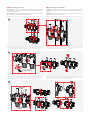
Disassembling the modules Disassemblaggio moduli
1
WARNING. The module assembly/disassembly operations must take place in a free, accessible
place with the manifold NOT connected to the system pipes and NOT supported on the relative
brackets.
WARNING. The disassembly of the modules must be carried out only in case of real necessity
in order not to risk compromising the hydraulic seal.
3
3) premere una chiave alla volta contro il modulo per sollevare le alette “C” e
ruotarlo per poterlo sganciare da un primo lato; durante questa operazione
prestare attenzione a non perdere o danneggiare l’O-Ring “D”;
C
D
PUSH AND
TURN
PUSH
REMOVE
PUSH AND
TURN
C
PUSH AND
TURN
PUSH AND
TURN
D
REMOVE
3) press one spanner at a time against the module to raise the fi ns “C” and
rotate the module, so that it can be disassembled from the fi rst side; when
doing this, be careful not to lose or damage the O-Ring “D”;
1) aprire i collarini con aggancio a clip e rimuovere i collettori dalle zanche; 1) open the supports with clip connections and remove the manifolds from the brackets;
2) posizionare una delle due chiavi R73FPY001 nella parte anteriore del
modulo e l’altra nella parte posteriore, in modo tale che le protuberanze “A”,
“B” e “C” delle chiavi si incastrino nelle feritoie “A”, “B” e “C” del modulo;
2) position one of the two R73FPY001 spanners in the front part of the module
and the other in the rear part, so that the protrusions “A”, “B” and “C” of the
spanners slide into the slots “A”, “B” and “C” on the module;
2
C
A
B
A
B
C
R73FPY001
C
A
B
A
B
C
R73FPY001

6
4
4) ripetere le operazioni 2 e 3 anche per sganciare il secondo lato del
modulo che si desidera rimuovere;
REMOVE
PUSH AND
TURN
PUSH AND
TURN
PUSH AND
TURN
PUSH AND
TURN
REMOVE
4) repeat steps 2 and 3 to disassemble the second side of the module that
needs to be removed;
5) una volta rimosso il modulo desiderato, riassemblare il collettore:
- assicurarsi che l’O-Ring “D” sia correttamente calzato sul raccordo maschio
del modulo (completamente a battuta), lubrifi candolo con scivolante idoneo
al materiale (EPDM) e all’utilizzo nell’impianto (es. lubrifi canti/scivolanti
siliconici). Durante questa operazione prestare attenzione a lubrifi care il
solo O-Ring e non le parti in plastica adiacenti;
- inserire il modulo con raccordo maschio nella corrispettiva femmina del
modulo adiacente (inclinato di circa 45°);
- ruotare entrambi i moduli per allinearli, facendo in modo che la
protuberanza “E” si incastri nelle feritoie “A” e “B”, mentre la protuberanza “F”
si incastri nella feritoria “C”, fi no all’udire del “CLICK” di avvenuto aggancio;
5
A
B
C
F
D
E
C
F
B
A
45°
A
B
C
F
D
E
C
F
B
A
5) after removing the module, reassemble the manifold:
- make sure the O-Ring “D” is correctly inserted on the male fi tting of the
module (pushed down as far as it will go), lubricating it with a suitable lubricant
for the material (EPDM) and for the intended use of the system (eg. silicone
lubricants). During this operation pay attention to lubricate the O-Ring only
and not the adjacent plastic parts;
- insert the module with the male fi tting in the corresponding female fi tting of
the adjacent module (rotated by about 45°);
- rotate both modules to align them, ensuring that protrusion “E” slides into
slots “A” and “B” and protrusion “F” slides into slot “C” until a click is heard;
6) ricollocare i collettori sulle zanche chiudendo i collarini.
6
6) replace the manifolds on the brackets and close the supports.

7
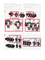
Assembling the modules Assemblaggio moduli
1) aprire i collarini con aggancio a clip e rimuovere i collettori dalle zanche; 1) open the supports with clip connections and remove the manifolds from the brackets;
1
2
2) posizionare una delle due chiavi R73FPY001 nella parte anteriore del
modulo e l’altra nella parte posteriore, in modo tale che le protuberanze “A”,
“B” e “C” delle chiavi si incastrino nelle feritoie “A”, “B” e “C” del modulo;
C
A
B
A
B
C
R73FPY001
C
A
B
A
B
C
R73FPY001
2) position one of the two R73FPY001 spanners in the front part of the module
and the other in the rear part, so that the protrusions “A”, “B” and “C” of the
spanners slide into the slots “A”, “B” and “C” on the module;
3) premere una chiave alla volta contro il modulo per sollevare le alette “C” e
ruotarlo per poterlo sganciare da un primo lato; durante questa operazione
prestare attenzione a non perdere o danneggiare l’O-Ring “D”;
3
C
PUSH AND
TURN
PUSH
PUSH AND
TURN
REMOVE
C
PUSH AND
TURN
PUSH AND
TURN
REMOVE
3) press one spanner at a time against the module to raise the fi ns “C” and
rotate the module, so that it can be disassembled from the fi rst side; when
doing this, be careful not to lose or damage the O-Ring “D”;
AVVERTENZA. Le operazioni di assemblaggio/disassemblaggio moduli devono avvenire in
ambiente libero e accessibile, con collettore NON collegato alle tubazioni dell’impianto e NON
alloggiato sulle apposite zanche.
AVVERTENZA. L’assemblaggio di nuovi moduli deve essere effettuato solo in caso di effettiva
necessità per non rischiare di compromettere la tenuta idraulica.
WARNING. The module assembly/disassembly operations must take place in a free, accessible
place with the manifold NOT connected to the system pipes and NOT supported on the relative
brackets.
WARNING. The assembly of new modules must be carried out only in case of real necessity in
order not to risk compromising the hydraulic seal.

8
4) inserire il nuovo modulo e riassemblare il collettore:
- assicurarsi che l’O-Ring “D” sia correttamente calzato sul raccordo maschio
del modulo (completamente a battuta), lubrifi candolo con scivolante idoneo
al materiale (EPDM) e all’utilizzo nell’impianto (es. lubrifi canti/scivolanti
siliconici). Durante questa operazione prestare attenzione a lubrifi care il
solo O-Ring e non le parti in plastica adiacenti;
- inserire il modulo con raccordo maschio nella corrispettiva femmina del
modulo adiacente (inclinato di circa 45°);
- ruotare entrambi i moduli per allinearli, facendo in modo che la
protuberanza “E” si incastri nelle feritoie “A” e “B”, mentre la protuberanza “F”
si incastri nella feritoria “C”, fi no all’udire del “CLICK” di avvenuto aggancio;
4
CLICK
A
B
C
D
D
E
F
E
F
A
B
CA
B
C
F
INSERT
INSERT
NEW MODULE
A
B
C
D
D
E
F
E
F
INSERT
NEW MODULE
CLICK
A
B
C
F
4) insert the new module, then reassemble the manifold:
- make sure the O-Ring “D” is correctly inserted on the male fi tting of the
module (pushed down as far as it will go), lubricating it with a suitable lubricant
for the material (EPDM) and for the intended use of the system (eg. silicone
lubricants). During this operation pay attention to lubricate the O-Ring only
and not the adjacent plastic parts;
- insert the module with the male fi tting in the corresponding female fi tting of
the adjacent module (rotated by about 45°)
- rotate both modules to align them, ensuring that protrusion “E” slides into
slots “A” and “B” and protrusion “F” slides into slot “C” until a click is heard;
5) ricollocare i collettori sulle zanche chiudendo i collarini.
5
5) replace the manifolds on the brackets and close the supports.

9
Regolazioni collettore di mandata
La regolazione dei singoli circuiti dell’impianto va eff ettuata tramite i
misuratori di portata presenti sui moduli di mandata, che hanno anche la
funzione di detentori di regolazione.
Per eff ettuare la regolazione procedere come segue:
1) rimuovere il cappuccio rosso di protezione;
2) ruotare manualmente la ghiera nera alla base del fl ussimetro per aprire
o chiudere il circuito; il valore di portata desiderato è leggibile tramite la
scala graduata del misuratore di portata;
3) a regolazione ultimata riposizionare il cappuccio rosso protettivo.
Regulating the system circuits Regolazione circuiti dell’impianto
1 2 3
Regulating the delivery manifold
The individual system circuits are regulated via the fl ow meters on the delivery
modules (that also act as adjustment lockshield).
To make the adjustment proceed as follows:
1) remove the protective red cap;
2) manually rotate the black ring nut at the base of the fl ow meter to open or
close the circuit; the desired fl ow rate value can be read by the graduated
scale of the fl ow meter;
3) when the adjustment is complete, refi t the red protective cap.
Regolazioni collettore di ritorno
La regolazione dei singoli circuiti sugli stacchi di ritorno può essere
eff ettuata manualmente ruotando il volantino blu, oppure installando delle
teste elettrotermiche normalmente chiusi R473/R473M.
Per installare le teste elettrotermiche procedere come segue:
1) rimuovere il volantino blu ed avvitare la ghiera R453FY002 con attacco
M30 x 1,5 mm (compresa nella confezione);
2) montare la testa elettrotermica sulla ghiera esercitando una pressione
suffi ciente all’incastro;
3) ruotare in senso orario la testa elettrotermica di circa 15° sino ad udire lo
scatto di gancio (coppia max. 5 Nm). Per sganciare la testa ruotarla di 15°
in senso antiorario;
4) spingere verso l’interno il bottone rosso di blocco e collegare
elettricamente la testa rispettando scrupolosamente lo schema
presente sulle istruzioni della stessa.
1
R453FY002
R473/R473M
2
Regulating the return manifold
The individual circuits are regulated on the return outlets, either manually - by
turning the blue handwheel - or by installing normally closed R473/R473M
thermo-electric actuators.
To install the thermo-electric actuators proceed as follows:
1) remove the blue handwheel and tighten the R453FY002 ring nut with
M30 x 1,5 mm connection (included in the kit);
2) assemble the thermo-electric actuator on the ring nut, pressing just enough
to lock them together;
3) Turn the actuator about 15° clockwise until a click is heard (max. torque 5
Nm). To release the actuator, turn it 15° counterclockwise;
4) press the red lockout button and make the electrical connection of
the actuator, following the wired diagram supplied with the actuator
instructions.
3
15°
4
PUSH
AVVERTENZA. Per consentire un’agevole installazione
nel caso di ingresso con tubazioni da destra, le teste
elettrotermiche devono essere montate con il bottone rosso
rivolto verso l’interno della cassetta.
WARNING. To allow the installation in case of pipe inlet
from the right, the thermo-electric heads must be mounted
with the red button facing the inside of the cabinet.

10
Per il collegamento delle tubazioni dei circuiti dell’impianto si utilizzano
idonei adattatori per tubo rame, plastica o multistrato della serie R178E,
R179E (Eurocono) oppure R178, R179, R179AM (base 18).
AVVERTENZA. Durante il serraggio dell’adattatore è necessario utilizzare una controchiave per
tenere fermo il raccordo del collettore .
Collegamento dei circuiti dell’impianto
BACKUP
SPANNER
To connect the system circuit pipes use suitable adaptors for copper, plastic
or multilayer pipes from the R178E and R179E (Eurocone) or R178, R179 and
R179AM (Base 18) series.
WARNING. When tightening the adaptor it is necessary to use a backup spanner to hold the
manifold fi tting in stationary.
Connecting the system circuits
NOTA. Grazie ai raccordi eccentrici, anche nell’installazione con ingresso tubazioni da destra, il
collegamento delle tubazioni dei circuiti dell’impianto risulterà agevole e pratico.
NOTE. Thanks to the eccentric fi ttings, even in the installation with piping inlet from the right,
the connection of the pipe’s system circuits will be easy and practical.

11
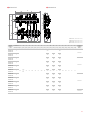
Dimensioni Dimensions
CODICE
PRODUCT
CODE
N° STACCHI
No. OUTLETS
A
[mm]
B
[mm]
C
[mm]
D
[mm]
E
[mm]
F
[mm]
G
[mm]
H
[mm]
I
[mm]
L
[mm]
M
[mm]
N
[mm]
O
[mm]
P
[mm]
Q
[mm]
R
[mm]
S
[mm]
T
[mm]
U
[mm]
CASSETTA
CABINET
R500-2
R553FP302
R553FP322 2
165
3/4”E
or
B.18
43 95 209 101 G1” 405 50
258
202
-
25
283
100 140 44 47 93
R500Y221
R553FP303
R553FP323 3 308 50 333
R553FP304
R553FP324 4 358 100 383
R500Y222
R553FP305
R553FP325 5 408 150 433
R553FP306
R553FP326 6 458 200 483
R553FP307
R553FP327 7 508 250 533
R553FP308
R553FP328 8 558 300 583
R500Y223
R553FP309
R553FP329 9 608 350 633
R553FP310
R553FP330 10 658 400 683
R553FP311
R553FP331 11 708 450 733
R553FP312
R553FP332 12 758 500 783 R500Y224
M
P
N
S
U
T
B
B
L
AI CII
G
G
E
H
FD
O
RQ
R500Y221 (400x650x85÷130 mm)
R500Y222 (600x650x85÷130 mm)
R500Y223 (800x650x85÷130 mm)
R500Y224 (1000x650x85÷130 mm)

12
Giacomini S.p.A.
Via per Alzo 39, 28017 San Maurizio d’Opaglio (NO) Italia
consulenza.prodotti@giacomini.com
+39 0322 923372 - giacomini.com
Avvertenze per la sicurezza. L’installazione, la messa in servizio e la periodica manutenzione
del prodotto devono essere eseguite da personale professionalmente abilitato, in accordo con
i regolamenti nazionali e/o i requisiti locali. L’installatore qualifi cato deve adottare tutti gli
accorgimenti necessari, incluso l’utilizzo di Dispositivi di Protezione Individuale, per assicurare la
propria incolumità e quella di terzi. L’errata installazione può causare danni a persone, animali o
cose nei confronti dei quali Giacomini S.p.A. non può essere considerata responsabile.
Safety Warning. Installation, commissioning and periodical maintenance of the product
must be carried out by qualifi ed operators in compliance with national regulations and/or local
standards. A qualifi ed installer must take all required measures, including use of Individual
Protection Devices, for his and others’ safety. An improper installation may damage people,
animals or objects towards which Giacomini S.p.A. may not be held liable.
Smaltimento imballo. Scatole in cartone: raccolta differenziata carta. Sacchetti in plastica e
pluriball: raccolta differenziata plastica.
Package Disposal. Carton boxes: paper recycling. Plastic bags and bubble wrap: plastic
recycling.
Smaltimento del prodotto. Alla fi ne del suo ciclo di vita il prodotto non deve essere smaltito
come rifi uto urbano. Può essere portato ad un centro speciale di riciclaggio gestito dall’autorità
locale o ad un rivenditore che offre questo servizio.
Product Disposal. Do not dispose of product as municipal waste at the end of its life cycle.
Dispose of product at a special recycling platform managed by local authorities or at retailers
providing this type of service.
Altre informazioni. Per ulteriori informazioni consultare il sito giacomini.com o contattare il
servizio tecnico. Questa comunicazione ha valore indicativo. Giacomini S.p.A. si riserva il diritto di
apportare in qualunque momento, senza preavviso, modifi che per ragioni tecniche o commerciali
agli articoli contenuti nella presente comunicazione. Le informazioni contenute in questa
comunicazione tecnica non esentano l’utilizzatore dal seguire scrupolosamente le normative e le
norme di buona tecnica esistenti.
Additional information. For more information, go to giacomini.com or contact our technical
assistance service. This document provides only general indications. Giacomini S.p.A. may change
at any time, without notice and for technical or commercial reasons, the items included herewith.
The information included in this technical sheet do not exempt the user from strictly complying
with the rules and good practice standards in force.
-
 1
1
-
 2
2
-
 3
3
-
 4
4
-
 5
5
-
 6
6
-
 7
7
-
 8
8
-
 9
9
-
 10
10
-
 11
11
-
 12
12


in altre lingue
Documenti correlati
-
Giacomini R500-2E Istruzioni per l'uso
-
-
-
-
-
-
-
-
-
Altri documenti
-
agape ASPE037V Assembly Instructions
-
-
Immergas 3.023959 Manuale utente
-
-
Ferrari Mondial Manuale del proprietario
-
-
Ducati 2006 Monster S2R800 Workshop Manual
-
-
-
DAB 1/2/3 KVC AD Istruzioni per l'uso