Lindy 32327 Manuale utente
- Categoria
- Switch KVM
- Tipo
- Manuale utente
Questo manuale è adatto anche per

© LINDY ELECTRONICS LIMITED & LINDY-ELEKTRONIK GMBH - FIRST EDITION (March 2016)
Quad View KVM Switch Pro
Quick Installation Guide English
Schnellstartanleitung Deutsch
Guide d’Installation Rapide Français
Guida di installazione rapida Italiano
No. 32327
www.lindy.com
Tested to Comply with
FCC Standards
For Home and Office Use!


Quick Installation Guide English
Introduction
We are glad that you have chosen a LINDY product and thank you for having placed your trust in us. You can rely
on our products and our good service at any time.
The LINDY Quad View KVM Switch Pro simultaneously displays video signals from four digital sources on a single
screen as well as giving individual Keyboard & Mouse control over connected computers. In addition a second
display can be connected (Full Screen Mode only!), so that you can directly control or work on one of the
computers without having to disrupt the monitoring of the other connected computers. An optional Remote IP
Module (LINDY No. 32328) is available which allows you to create a Remote Console, giving you full remote
control over the connected computers at distances of up to 100m (200m via Gigabit Ethernet Switch).
The complete description of the functions and feature of this switch is available in the full manual you can easily
download from our website www.lindy.com in the page dedicated to this product.
Package Contents
1 x Quad View KVM Switch Pro
1 x IEC Power Adapter 100 - 240VAC / 12V 5.0A (5.5/2.1mm DC connector)
1 x IEC mains cable
1 x LINDY Manual (QIG)
1 x RJ45 to DB9 female (RS232) serial cable
4 x DVI-D Cable 2m long
4 x USB A/B m/m cable 1.80m long
4 x Audio Stereo Cable (Jack 3.5mm m/m) 1.80m long
1 x 19” Rack Mount Kit (brackets & small screws)
Product Overview
Please refer to the following overview to explore the basic functions of this product. To get a full explanation of all
the features of this product please check the full manual which you can find in our website www.lindy.com
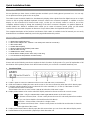
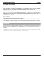
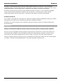
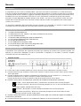
Front Panel View
1 – USB 2.0 ports to connects USB devices that can be used with of the connected PCs
2 – OSD menu button to display the menu to the screen. It also acts as Enter key when the OSD is already open.
3 – Computer selection buttons to let you select the PC to be controlled (1, 2, 3 and 4). If the button is lit a PC
is connected and active on that port.
These buttons also act as cursor arrows (///) when the OSD menu is open.
4 – Display Mode buttons to be used to select the display mode to be shown on the main console screen:
Full View – Only the selected PC’s video signal will be shown on the main screen
PIP (Picture In Picture) View – Shows a main picture from one PC and small picture from another
PC (you can choose both the channels from the OSD Menu).
Quad View – Shows all the 4 channels in a single screen.
PAP (Picture and Picture) View – Shows a main picture on the left side and the other 3 channels
on the right side of the screen.
5 – Display Mode Menu button to directly open the OSD menu where you can choose the desired display mode
6 – Restart button to be pressed with a paperclip to hard reboot the unit

Quick Installation Guide English
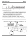
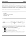
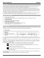
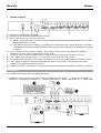
Back Panel View
1 – Main Power Switch
2 – DC port to connect the included power supply unit
3 – RJ 45 I/O ports that have 2 main functions:
a) RS232 – (Input port only): allows you to control the unit through a RS232 connection using the RJ45 to
RS232 (DB9) cable.
b) Daisy Chain Port (Input and Output): connect up to 8 switch No.32327 in a cascade configuration to control
a maximum of 32 computers (please refer to the full manual for a complete description of this function)
4 – Console Ports to connect the local USB Keyboard & Mouse, the DVI-D Monitors (digital only:
please don’t use DVI to VGA cables and adapter on these ports) and Audio Speakers
The A port is for the main monitor and the B is for the auxiliary monitor (full screen mode only).
5 – Computer ports to connect with the supplied cables (DVI-D, USB and Audio) each PC
6 – Reset button to restore the factory default setting. Insert a paper clip before switching on the Switch.
7 – LAN port to connect the unit to the optional remote unit (no.32328 – Not included). Please refer to the full
manual or to the manual for No.32328 for further information.
8 – Dip Switch set that must match the same sequence set on the optional remote unit no. 32328 (not included)
Installation
To begin to work with this switch please follow these steps:
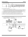
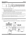
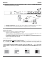
1) Connect the local console as follow (please refer to the picture below): 1 – Local DVI-D Main Monitor, 2 –
Local DVI-D secondary monitor (Optional), 3 – Local USB Keyboard, 4- Local USB Mouse and 5 – Local
Speakers

Quick Installation Guide English
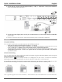
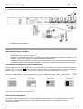
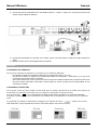
2) Connect all the computers with the supplied cables (1 - USB, 2 - Audio and 3 - DVI-D) to the related PC
ports on the switch as shown below:
3) Connect the Power Supply Unit to the DC port on switch and then to a mains socket with the included IEC
power cable
4) Power on the switch with the main power switch and then power on all the other equipment.
Operations
Computer Switching
You can switch control of the connected computers with 3 different methods:
- Using the front panel computer selection buttons (1, 2, 3 and 4)
- Through the keyboard with a hotkey combination. The default keys sequence to select the PC is: Scroll
Lock + Scroll Lock + (n) where (n) is the port number where is connected the desired PC.
- Through the OSD. To open the menu on the screen you can use the related front panel button or the
hotkey sequence Scroll Lock + Scroll Lock + Space Bar then choose the port connected to the computer
you want to control
Video Mode Switching
You can easily choose the video mode for the main local monitor using the Video Mode buttons on the front panel
(please refer to the front panel description).
For the PIP mode ( ) the currently selected PC is displayed in the main screen. To switch the subordinate
display please press again the PIP button and then the desired PC button (1-4) on the front panel.
It is possible to control the Video Mode also pressing the display mode menu button ( ). After that an OSD
menu will be shown letting you choose the desired video mode directly with the mouse and keyboard:
You can also directly choose the video mode through a hotkey combination. By default this is Scroll Lock + Scroll
Lock + (v) where (v) can be “F” for the Full View, “I” for the PIP view, “Q” for the Quad view or “A” for the PAP view.

Quick Installation Guide English
USB and Audio Channel Switching
By default the Audio signal and the Shared USB hub on the front panel will be switched together with the PC
channel. It is possible to switch them separately as follows:
For the USB Hub you can disable the binding between PC and USB channel by pressing the hotkey combination
Scroll Lock + Scroll Lock + X. To enable it again use the combination Scroll Lock + Scroll Lock + Z.
When disabled you can switch the front USB hub alone on a different PC using the combination: Scroll Lock +
Scroll Lock + F1 or F2 or F3 or F4.
For the Audio Channel you can disable the binding switch between PC and Audio channel by pressing the hotkey
combination Scroll Lock + Scroll Lock + V. To enable it again use the combination Scroll Lock + Scroll Lock + C.
When disabled you can switch the front USB hub alone on a different PC using the combination: Scroll Lock +
Scroll Lock + F5 or F6 or F7 or F8.
Advanced Operation
It is possible to fully customize the operation of this device through the OSD menu advanced options. Please refer
to the complete manual to get a full overview of these features.
Please refer to the full manual also for the Daisy Chain connection between more switches and for the RS232
control description.
Troubleshooting
If you are experiencing any problem in getting the video signal or controlling one or more computers please refer to
the full manual that can be downloaded on our website www.lindy.com in the page dedicated to this product to fix
the problem.
If a USB device connected to the front panel USB port is not detected by one or more PC please check if this was
previously installed on them connecting it directly to USB port of the related PC.

Benutzerhandbuch Deutsch
Einführung
Wir freuen uns, dass Ihre Wahl auf ein LINDY-Produkt gefallen ist und danken Ihnen für Ihr Vertrauen. Sie können
sich jederzeit auf unsere Produkte und einen guten Service verlassen.
Dieser KVM Switch erlaubt die Steuerung und Kontrolle von vier Computern gleichzeitig auf nur einem oder zwei
Bildschirmen. Maus und Tastatur werden dabei immer auf den gerade aktiven Computer geschaltet, der bei Bedarf
auf dem optionalen zweiten Monitor einzeln groß dargestellt wird, so dass der Erstbildschirm zur gleichzeitigen
Kontrolle aller anderen Monitorsignale permanent zur Verfügung steht. Mit dem optionalen Extender Nr.32328 ist
es ebenso möglich, den Erstbildschirm bis zu 100m entfernt über Cat.6 Kabel zu platzieren.
Wenn Sie über diese Kurzanleitung hinaus gehende Informationen benötigen finden Sie das vollständige
ausführliche englische Handbuch zu diesem Switch zum Download auf unserer Webseite.
Lieferumfang
1 x Quad View KVM Switch Pro
1 x IEC Netzteil 100…240VAC / 12V ~5.0A - 5,5/2,1mm DC Hohlstecker
1 x IEC Netzkabel
1 x LINDY Handbuch
1 x serielles Kabel RJ45 an DB9 Buchse (RS232)
4 x DVI-D Kabel, 2m
4 x USB A/B Kabel, ca. 1,8m
4 x Audio Stereo Kabel 3,5mm, ca. 1,8m
1 x 19” Rack Mount Kit (Winkel und Schrauben zur Befestigung am Switch)
Übersicht
Frontansicht mit Elementen
1 – USB 2.0 Anschlüsse für USB Devices (nicht USB Tastatur/Maus!) – sie unterstützen USB Hubs und werden
auch an den aktiven Computer verbunden (Default)
2 – OSD Menu Taste – ruft das OSD Menu auf sowie Enter Taste zum Bestätigen von Kommandos.
3 – Computer Auswahl bzw. Navigations-Tasten – zur Auswahl des aktiven Computers (1,2,3 oder 4). Der aktive
Computer wird durch eine leuchtende Taste angezeigt. Wenn das OSD Menu angezeigt wird dienen diese Tasten
als Navigationstasten (///).
4 – Display Mode Tasten – zur Wahl der Anzeigeart auf dem Erstbildschirm:
Full View – Ausschließlich der aktive Computer wird im Vollbild gezeigt
PIP (Picture In Picture) – Vollbild für einen und kleine Darstellung für einen weiteren Computer,
Auswahl der Computer/Kanäle über OSD Menu.
Quad View – Zeigt alle 4 Bilder in Quadranten-Darstellung.
PAP (Picture And Picture) – Zeigt ein großes Bild und drei kleine Darstellungen am rechten Rand.
5 – Display Mode Menu Taste zum Öffnen des OSD, in dem dann der Anzeigemodus gewählt werden kann
6 – Reset Taste zum Reset & Reboot des KVM Switch (verwenden Sie eine Büroklammer o. ä.)

Benutzerhandbuch Deutsch
Rückansicht mit Elementen
1 – Netzschalter
2 – DC Anschlussbuchse für Netzteil
3 – 2x RJ45 I/O Ports – Stellen 2 Hauptfunktionen zur Verfügung:
c) RS232 – (Nur Input): Zur Steuerung über eine serielle Verbindung mit dem beiliegenden RJ45/DB9) Kabel.
d) Daisy Chain Port (Input und Output): Es können bis zu 8 KVM Switch Nr.32327 kaskadiert werden um bis
zu 32 Computer anzuschließen (detaillierte Angaben finden Sie im ausführlichen englischen Handbuch)
4 – Konsolenanschlüsse für USB Tastatur & Maus, DVI-D Monitor und Lautsprecher/Headset/Line.
Der Erstbildschirm muss an den DVI-D A Port angeschlossen werden, Port B für den jeweils aktiven Computer.
5 – Computer Anschlüsse, verwenden Sie die beiliegenden Kabel DVI-D, USB und 3,5mm Audio
6 – Reset Taste zum Reset & Reboot des KVM Switch (verwenden Sie eine Büroklammer o. ä.)
7 – LAN/RJ45 Port zum Anschluss des optionalen Remote Extenders Nr.32328 (bitte separat bestellen)
8 – DIP Switch – muss ggf. die identischen Einstellungen haben wie der Remote Extender Nr. 32328
Installation
1) Schließen Sie die lokale Konsole an wie unten gezeigt:
1 – Lokaler DVI-D Erstbildschirm, 2 – Lokaler DVI-D Bildschirm (aktiver Computer, optional),
3 – USB Tastatur, 4 – USB Maus, 5 – Lautsprecher/Headset/Line

Benutzerhandbuch Deutsch
2) Schließen Sie die Computer mit den mitgelieferten Kabeln an wie in folgendem Bild:
3) Schließen Sie das Netzteil an
4) Schalten Sie den Switch und die angeschlossenen Geräte ein.
Betrieb
Umschalten des aktiven Computers
Sie können zwischen drei Umschaltmethoden wählen:
- Bedientasten 1 bis 4 an der Frontblende
- Eingabe von Umschalt-Hotkeys über die Tastatur. Die Default-.Einstellung ist: ROLLEN + ROLLEN + (n)
wobei (n: 1 bis 4) die Portnummer des angeschlossenen Computers ist.
- Eingabe über OSD. Um das OSD zu Öffnen drücken Sie entweder die OSD Taste an der Frontblende oder
verwenden Sie den Hotkey ROLLEN + ROLLEN + Leertaste und wählen dann den Anschluss 1 bis 4 aus.
Umschalten des Anzeigemodus auf dem Erstbildschirm
Der Anzeigemodus für den Erstbildschirm kann einfach über die Fronttasten mit Ihren Piktogrammen eingestellt
werden. Im PiP Modus wird der aktive Computer immer im Großbild gezeigt. Um den Computer im
Kleinbild umzuschalten drücken Sie erneut die PiP Taste und dann den entsprechenden Port 1 bis 4.
Alternativ kann der Anzeigemodus durch Drücken der Display Mode Menu Taste
per OSD geändert werden. Folgende Anzeige erscheint und erlaubt die Auswahl per Maus oder Tastatur:
Eine weitere Alternative ist die Direktwahl per Tastatur-Hotkey ROLLEN + ROLLEN + “f” für Full View, “i” für PIP
view, “q” für Quad view oder “a” für PAP view.
USB und Audio Umschaltung
Per Default werden die USB 2.0 Ports an der Frontblende sowie die Audio-Ports zusammen mit den USB & DVI
KVM-Ports an der Rückseite des Switch umgeschaltet. Sie können aber auch abgekoppelt und separat
umgeschaltet werden:

Benutzerhandbuch Deutsch
Die USB 2.0 Frontanschlüsse können über die Hotkey Eingabe ROLLEN + ROLLEN + x vom Umschalten
entkoppelt werden. Über den Hotkey ROLLEN + ROLLEN + F1 oder F2 oder F3 oder F4 können sie dann separat
umgeschaltet werden. ROLLEN + ROLLEN + z koppelt die Ports wieder an die KVM-Umschaltung.
Die Audio-Anschlüsse können über die Hotkey Eingabe ROLLEN + ROLLEN + v vom Umschalten entkoppelt
werden. Über den Hotkey ROLLEN + ROLLEN + F5 oder F6 oder F7 oder F8 können sie dann separat
umgeschaltet werden. ROLLEN + ROLLEN + c koppelt die Ports wieder an die KVM-Umschaltung.
Erweiterte Funktionen
Es ist möglich, den Betrieb des Geräts über das OSD-Menü Erweiterte Optionen detaillierter anzupassen. Weitere
Informationen dazu finden Sie im ausführlichen englischen kompletten Handbuch.
Dort finden Sie auch für die Daisy-Chain-Verbindung zwischen mehreren Switches und die Beschreibung der
RS232-Steuerung.
Fehlersuche
Sollten Probleme mit Ihren Bildsignalen oder mit der Steuerung der Computer auftreten so finden Sie weitere
Hinweise im ausführlichen englischen Handbuch welches zum Download von unserer Webseite verfügbar ist.
Wenn ein an den Frontseitigem USB-Anschlüssen angeschlossenes USB-Gerät von einem oder mehreren PC
nicht erkannt wird schließen Sie das Gerät bitte kurz direkt am entsprechenden Computer an damit es sicher
erkannt wird und alle Treiber installiert werden. Danach sollte es auch über den KVM Switch funktionieren.
Sollten Sie weitere Probleme nicht lösen können so kontaktieren Sie bitte Ihren Händler oder den Techniksupport
von LINDY. Sie finden die Kontaktinformationen auf unseren Webseiten www.lindy.com

Manuel Utilisateur Français
Introduction
Merci d’avoir choisi ce produit LINDY, nous vous remercions pour la confiance que vous nous accordez. Vous
pouvez compter à tout moment sur la qualité de nos produits et de notre service.
Ce switch KVM Quad View vous permet de contrôler jusqu’à 4 ordinateurs avec un affichage unique sur le
moniteur principal, vous laissant le choix à tout moment du système contrôlé par les souris et clavier connecté au
switch. Il est également possible de connecter un moniteur secondaire afin d’afficher en mode plein écran un des
ordinateurs connectés. Un module extender est disponible (N°Art.32328), il vous permet de connecter la console
principale à une distance pouvant aller jusqu’à 100m du switch.
La description complète des fonctions et caractéristiques de ce module sont disponibles dans le manuel complet
du Quad View KVM Switch Pro disponible au téléchargement sur la page du produit sur www.lindy.com.
Contenu de l’emballage
1 x Switch KVM Quad View Pro
1 x alimentation IEC 100…240VAC / 12V 5.0A Modèle EA10521C-120 – connecteur DC 5,5/2,1mm
1 x cordon secteur IEC
1 x manuel LINDY (QIG)
1 x câble série RJ45 vers DB9 femelle (RS232)
4 x câbles DVI-D, longueur 2m
4 x câbles USB A/B mâle/mâle, longueur 1,80m
4 x câbles audio stéréo (Jack 3,5mm mâle/mâle), longueur 1,80m
1 x kit de montage en rack 19” (équerres & visserie)
Vue d’ensemble
Merci de suivre la procédure suivante pour installer et explorer les fonctions basiques de ce produit. Pour plus de
détails sur ce produit, merci d’utiliser le manuel complet disponible sur www.lindy.com
Panneau avant
1 – Ports USB 2.0 pour la connexion de périphériques USB qui peuvent être connectés à chacun des PC reliés.
2 – Bouton de menu OSD pour afficher le menu à l’écran. Il agit aussi comme bouton Entrée lorsque le menu OSD
est ouvert.
3 – Boutons de sélection d’ordinateur qui permet de sélectionner le PC à contrôler (1, 2, 3 et 4). Si le bouton est
allumé, le PC correspondant est actif. Ces boutons agissant aussi en tant que flèches de navigations (///)
lorsque le menu OSD est ouvert.
4 – Boutons de mode d’affichage, pour la sélection le mode d’affichage de la console principale:
Plein écran (Full View) – le signal vidéo du PC connecté s’affiche uniquement
PIP (Picture In Picture) – affiche le PC principal et une vignette d’un autre PC connecté (vous
pouvez effectuer le choix dans le menu OSD).
Quad View – affiche les 4 canaux dans un seul écran.
PAP (Picture And Picture) View – affiche le PC principal sur la gauche et les 3 autres canaux sur la
partie droite de l’écran.
5 – Bouton de menu du mode d’affichage pour ouvrir directement le menu OSD où vous pouvez choisir le mode
d’affichage désiré
6 – Bouton Restart, pour redémarrer l’unité à l’aide d’un trombone par exemple

Manuel Utilisateur Français
Panneau arrière
1 – Bouton marche/arrêt
2 – Port DC pour le branchement de l’alimentation fournie
3 – Ports RJ 45 I/O qui ont 2 fonctions principales:
e) RS232 – (port Input uniquement) : vous permet de contrôler l’unité au travers d’une connexion RS232 en
utilisant le câble RJ45 vers RS232 (DB9).
f) Port Daisy Chain Port (Input et Output): vous permet de connecter jusqu’à 8 switch N°Art.32327 dans une
configuration en cascade pour contrôler un maximum de 32 ordinateurs (merci de vous référer au manuel
complet pour une description détaillée de ces fonctions)
4 – Ports Console local pour connecter clavier & souris, moniteurs DVI-D (numérique uniquement:
ne pas utiliser de câble DVI vers VGA ou des adaptateurs sur ces ports) et les haut-parleurs
Le port A est dédié au moniteur principal et le port B est dédié au moniteur auxiliaire (plein écran uniquement).
5 – Ports ordinateurs, à connecter avec les câbles inclus (DVI-D, USB et Audio) pour chaque PC
6 – Bouton Reset pour restaurer les paramètres par défaut. Insérez un trombone avant de mettre le switch sous
tension.
7 – Port LAN pour connecter l’unité à l’unité distante optionnelle (N°Art.32328 – non incluse). Merci de vous référer
au manuel complet et au manuel du N°Art.32328 pour plus d’informations.
8 – Dip Switch qui doivent correspondre au réglage effectué sur l’unité distante optionnelle N°Art. 32328 (non
inclus).
Installation
Pour commencer à utiliser ce switch, merci de suivre les étapes suivantes:
1) Connectez la console locale comme suit (référer vous à l’image ci-dessous): 1 – Moniteur principal local
DVI-D, 2 – moniteur secondaire local DVI-D (optionnel), 3 – clavier USB local, 4- souris USB locale, 5 –
haut-parleurs

Manuel Utilisateur Français
2) Connectez tous les ordinateurs avec les câbles fournis (1 - USB, 2 - Audio et 3 - DVI-D) aux ports PC du
switch comme indiqué ci-dessous:
3) Connectez l’alimentation au port DC sur le switch, puis à une prise secteur à l’aide du cordon secteur IEC
inclus
4) Mettez le switch et tous les équipements sous tension.
Utilisation
Commutation des ordinateurs
Vous pouvez commuter les ordinateurs à controler avec 3 méthodes différentes:
- En utilisant les boutons de sélections présents sur le panneau avant (1, 2,3 et 4)
- Via raccourci clavier. La séquence de touches par défaut est: Arrêt Défil. + Arrêt Défil.+ (n) où (n) est le
numéro de port auquel le PC est connecté.
- Via le menu OSD. Pour ouvrir le menu à l’écran vous pouvez utiliser le bouton sur le panneau avant ou le
raccourci clavier Arrêt Défil.+ Arrêt Défil.+ barre espace et choisir ensuite le port correspondant au PC
connecté à contrôler
Commutation du mode vidéo
Vous pouvez choisir de façon simple le mode vidéo pour le moniteur principal local en utilisant les boutons de
mode vidéo sur le panneau avant (merci de vous référer à la description du panneau avant).
Pour le mode PIP ( ) le PC sélectionner est affiché dans l’écran principal. Pour commuter l’affichage
secondaire, veuillez appuyez une seconde fois sur le bouton PIP et le bouton du PC ensuite (1-4) sur le panneau
avant.
Il est possible de contrôler le mode vidéo en appuyant sur le bouton du menu ( ) . Après cela un menu
OSD s’affichera, vous permettant de choisir le mode vidéo désiré, avec souris et clavier:

Manuel Utilisateur Français
Vous pouvez aussi chosir le mode vidéo par raccourci clavier. Par défaut le raccourci est Arrêt Défil. + Arrêt Défil. +
(v) où (v) peut être “F” pour Full View, “I” pour PIP view, “Q” pour Quad view ou “A” pour PAP view.
Commutation USB et canal audio
Par défaut le signal audio et le hub USB de partage du panneau avant est commuter avec le port PC. Il est
possible de les commuter séparément comme suit:
Pour le hub USB, vous pouvez désactiver la liaison entre les ports PC et USB en entrant le raccourci clavier Arrêt
Défil. + Arrêt Défil. + X. Pour réactiver les liaisons entrez la combinaison Arrêt Défil. + Arrêt Défil. + Z.
Si la liaison est désactivée, vous pouvez commuter le hub USB sur un autre PC en utilisant la combinaison: Arrêt
Défil. + Arrêt Défil. + F1 ou F2 ou F3 ou F4.
Pour le canal audio, vous pouvez désactiver la liaison entre PC et canal audio en entrant le raccourci clavier Arrêt
Défil. + Arrêt Défil. + V. Pour réactiver la liaison, entrez Arrêt Défil. + Arrêt Défil. + C.
Si la liaison est désactivée, vous pouvez commuter le canal audio sur un PC différent en utilisant la combinaison:
Arrêt Défil. + Arrêt Défil. + F5 ou F6 ou F7 ou F8.
Utilisation avancée
Il est possible de personnaliser le fonctionnement de cet appareil via le menu d’options avancées OSD. Merci de
vous référer au manuel complet pour avoir un aperçu complet de ces fonctionnalités.
Merci de vous référer également au manuel au sujet des connexions en cascade (Daisy Chain) entre plusieurs
switch et pour le contrôle via RS232.
Dépannage
En cas de problèmes pour obtenir un signal vidéo ou le contrôle d’un ou plusieurs ordinateurs, merci de vous
référer au manuel complet disponible sur www.lindy.com, à la page dédiée du produit.
Si un périphérique USB connecté au port USB du panneau avant n’est pas détecté par un ou plusieurs PC, merci
de vérifier si celui-ci a été préalablement installé en le connectant directement au port USB du PC correspondant

Manuale Italiano
Introduzione
Vi ringraziamo per aver scelto un prodotto LINDY e per averci accordato la vostra fiducia. Lo switch KVM Quad
View Pro visualizza simultaneamente i segnali di 4 sorgenti video digitali su un singolo schermo oltre a consentirne
il controllo tramite mouse & tastiera. In aggiunta è possibile collegare uno schermo secondario (funzionante solo in
modalità Full Screen) per permettervi di lavorare su un PC monitorando costantemente gli altri sullo schermo
principale. E’ infine disponibile un modulo remoto IP (Art. 32328 – non incluso) che consente di creare una copia
remota della consolle principale ad un massimo di 100m di distanza (200m via Gigabit Ethernet Switch) tramite
comune cavo cat.5e o 6.
La descrizione dettagliata delle funzionalità di questo prodotto sono disponibili nel manuale completo facilmente
scaricabile dal nostro sito www.lindy.com nella pagina dedicata a questo prodotto.
Contenuto della confezione
1 x Quad View KVM Switch Pro
1 x Alimentatore IEC 100 - 240VAC / 12V 5.0A (connettore DC 5.5/2.1mm)
1 x Cavo alimentazione IEC
1 x Manuale LINDY (Questa guida rapida di installazione)
1 x Cavo seriale (RS232) da RJ45 a DB9 femmina
4 x Cavi DVI-D lunghezza 2m
4 x Cavi USB A/B m/m lunghezza 1.80m
4 x Cavi Audio Stereo (Jack 3.5mm m/m) lunghezza 1.80m
1 x Kit di montaggio a Rack 19” (staffe & viti)
Panoramica del prodotto
Vi preghiamo di far riferimento alla seguente panoramica per esplorare le funzioni base di questo prodotto. Per
ottenere una descrizione dettagliata di tutte le funzionalità vi preghiamo di consultare il manuale completo
scaricabile dal nostro sito www.lindy.com
Pannello frontale
1 – Porte USB 2.0 per connettere periferiche USB che possono essere utilizzate dai computer connessi
2 – Pulsante Menù OSD per visualizzare il menù sullo schermo. Funziona anche da tasto “Enter” quando il menù
OSD è già aperto.
3 – Pulsanti di selezione del Computer per permettervi di selezionare il PC da controllare (1, 2, 3 and 4). Se il
pulsante è illuminato un PC attivo è connesso ed attivo sulla relativo porta.
Questi pulsanti servono anche per spostarsi (///) quando il menù OSD è aperto.
4 – Pulsante “Display Mode” da utilizzare per selezionare la modalità di visualizzazione desiderata:
Full View – Solo il segnale video del PC selezionato è visualizzato sullo schermo principale
PIP (Picture In Picture) – Mostra una schermata principale da un PC e una secondaria da un altro
(potete scegliere entrambi dal menù OSD).
Quad View – Mostra tutti i 4 canali contemporaneamente sullo schermo principale.
PAP (Picture and Picture) – Mostra una schermata principale sul lato sinistro dello schermo
principale e gli altri 3 canali sul lato destro.
5 – Pulsante “Display Mode Menu” per aprire direttamente il menù OSD che consente di scegliere la modalità di
visualizzazione desiderata
6 – Pulsante di Riavvio da premere con una graffetta per effettuare un riavvio forzato dello swtich.

Manuale Italiano
Pannello posteriore
1 – Interruttore di alimentazione principale
2 – Porta DC per la connessione dell’alimentatore incluso
3 – Porte RJ 45 I/O che hanno 2 funzioni principali:
a) RS232 – (solo porta Input): consente il controllo tramite una porta seriale standard utilizzando il cavo R45 -
RS232 (DB9) fornito a corredo.
b) Porte Daisy Chain (Input e Output): vi permettono di connettere fino ad 8 switch No.32327 in cascata e
controllare un massimo di 32 computer (fate riferimento al manuale completo per la descrizione di questa
funzione)
4 – Porte Consolle locale per collegare Tastiera & Mouse USB, i monitor DVI-D (solo digitali: non utilizzate
adattatori e cavi DVI / VGA su queste porte) e Casse Audio
La porta A è per il monitor principale mentre la B è per il monitor ausiliario(solo modalità Full Screen).
5 – Porte Computer per collegare ogni PC con i cavi forniti a corredo (DVI-D, USB e Audio)
6 – Pulsante Reset per ripristinare le impostazioni di fabbrica inserendo una graffetta prima di accendere lo switch.
7 – Porta LAN per connettere l’unità remota opzionale (Art.32328 – Non inclusa). Fate riferimento al manuale
completo per maggiori informazioni a riguardo.
8 – Selettori (Dip Switch) da impostare con la stessa sequenza di quelli dell’unità opzionale art.32328 (non inclusa)
Installazione
Per installare il prodotto utilizzate la seguente procedura:
1) Collegate la console locale come segue (fate riferimento alla figura sotto): 1 – Monitor DVI Principale, 2 –
Monitor DVI Secondario (Opzionale), 3 – Tastiera USB locale, 4- Mouse USB locale e 5 – Casse locali

Manuale Italiano
2) Collegate tutti i computer con i cavi forniti come segue: 1 - USB, 2 - Audio e 3 - DVI-D alle relativi porte sullo
switch come riportato nella figura seguente:
3) Collegate l’alimentatore alla porta DC sullo switch e ad una presa di alimentazione con il cavo di
alimentazione IEC incluso
4) Accendete lo switch con l’interruttore di alimentazione principale e poi tutti gli altri dispositivi
Utilizzo
Selezione del Computer
Potete selezionare il computer da controllare in tre differenti modi:
- Utilizzando i pulsanti del pannello frontale (1, 2, 3 e 4)
- Tramite la tastiera con una combinazione di tasti. La combinazione preimpostata is: Bloc Scorr + Bloc
Scorr + (n) dove (n) è il numero di porta a cui è connesso il computer desiderato.
- Tramite il menù OSD. Per aprire questo menù a schermo utilizzate il tasto dedicato sul pannello frontale o
la combinazione di tasti Bloc Scorr + Bloc Scorr + Barra Spaziatrice e poi selezionate la porta a cui è
connesso il computer che volete controllare
Selezione Video Mode
Potete facilmente selezionare la modalità Video desiderata sul monitor principale utilizzando i pulsanti sul pannello
frontale (fate riferimento alla descrizione del pannello frontale).
Per la modalità PIP( ) il PC selezionato correntemente sarà visualizzato sullo schermo principale. Per
selezionare il computer da visualizzare sullo schermo secondario premete ancora il tasto PIP e poi quello del PC
desiderato (1-4) sul pannello frontale.
E’ anche possibile selezionare il Video Mode premendo il pulsante Video Mode menù ( ). Dopo averlo
premuto comparirà un menù OSD che vi consentirà di scegliere la modalità video direttamente tramite mouse e
tastiera:

Manuale Italiano
Potete infine selezionare la modalità video tramite delle apposite combinazione di tasti. L’impostazione di fabbrica
prevede le seguenti sequenze: Bloc Scorr + Bloc Scorr + (v) dove (v) può essere “F” per la Full View, “I” per la PIP,
“Q” per la Quad View o “A” per la PAP.
Selezione del canale USB e Audio
Come impostazione predefinita i segnali Audio e le porte dell’Hub USB condiviso sul pannello frontale verrano
commutate insieme a quelle dei PC. E’ possibile commutarle separatamente come illustrato di seguito:
Per l’Hub USB potete disabilitare il legame con le porte PC premendo la sequenza di tasti Bloc Scorr + Bloc Scorr
+ X. Per riabilitarlo utilizzate la sequenza Bloc Scorr + Bloc Scorr + Z.
Una volta disattivato il legame potete commutare l’Hub separatamente sui computer connessi utilizzando la
combinazione Bloc Scorr + Bloc Scorr + F1 o F2 o F3 o F4.
Per il canale Audio potete disabilitare il legame con le porte PC premendo la sequenza di tasti Bloc Scorr + Bloc
Scorr + V. Per riabilitarlo utilizzate la sequenza Bloc Scorr + Bloc Scorr + C.
Una volta disattivato il legame potete commutare il canale Audio attivo separatamente fra i PC connessi utilizzando
la combinazione Bloc Scorr + Bloc Scorr + F5 o F6 o F7 o F8.
Funzioni Avanzate
E’ possibile configurare e personalizzare le funzioni di questo dispositivo tramite il menù OSD e le relative funzioni
avanzate. Per ottenere una descrizione dettagliata di tutte queste possibilità vi preghiamo di consultare il manuale
completo scaricabile dal nostro sito www.lindy.com
Fate sempre riferimento al manuale sopracitato per realizzare connessioni in cascata (Daisy Chain) di più switch e
per il controllo tramite porta RS232.
Risoluzione dei problemi
Se riscontrate problemi nel visualizzare i segnali video o nel controllo di uno o più computer fate riferimento al
manuale completo disponibile sul sito www.lindy.com nella pagine dedicata a questo prodotto.
Se un dispositivo USB connesso ad una delle porte del pannello frontale non è rilevato correttamente da uno o più
PC vi preghiamo di controllare che questo sia stato prima installato collegandolo direttamente ad una porta USB
libera del PC stesso.

CE/FCC Statement
CE Certification
This equipment complies with the requirements relating to Electromagnetic Compatibility Standards
EN55022/EN55024 and the further standards cited therein. It must be used with shielded cables only.
It has been manufactured under the scope of RoHS compliance.
CE Konformitätserklärung
Dieses Produkt entspricht den einschlägigen EMV Richtlinien der EU für IT-Equipment und darf nur
zusammen mit abgeschirmten Kabeln verwendet werden.
Diese Geräte wurden unter Berücksichtigung der RoHS Vorgaben hergestellt.
Die formelle Konformitätserklärung können wir Ihnen auf Anforderung zur Verfügung stellen
FCC Certification
This equipment has been tested and found to comply with the limits for a Class B digital device, pursuant
to part 15 of the FCC Rules. These limits are designed to provide reasonable protection against harmful
interference in a residential installation.
You are cautioned that changes or modification not expressly approved by the party responsible for
compliance could void your authority to operate the equipment.
This device complies with part 15 of the FCC Rules.
Operation is subject to the following two conditions:
1. This device may not cause harmful interference, and
2. This device must accept any interference received, including interference that may cause undesired
operation.
LINDY Herstellergarantie – Hinweis für Kunden in Deutschland
LINDY gewährt für dieses Produkt über die gesetzliche Regelung in Deutschland hinaus eine zweijährige
Herstellergarantie ab Kaufdatum. Die detaillierten Bedingungen dieser Garantie finden Sie auf der LINDY Website
aufgelistet bei den AGBs.
Hersteller / Manufacturer (EU): LINDY Electronics Ltd.
LINDY-Elektronik GmbH Sadler Forster Way
Markircher Str. 20 Teesside Industrial Estate, Thornaby
68229 Mannheim Stockton-on-Tees, TS17 9JY
GERMANY United Kingdom
Email: info@lindy.com , T: 0049 (0)621 470050 postm[email protected] , T: +44 (0) 1642 754000

Recycling Information
WEEE (Waste of Electrical and Electronic Equipment),
Recycling of Electronic Products
Europe, United Kingdom
In 2006 the European Union introduced regulations (WEEE) for the collection and recycling of all waste electrical
and electronic equipment. It is no longer allowable to simply throw away electrical and electronic equipment.
Instead, these products must enter the recycling process.
Each individual EU member state has implemented the WEEE regulations into national law in slightly different
ways. Please follow your national law when you want to dispose of any electrical or electronic products. More
details can be obtained from your national WEEE recycling agency.
Germany / Deutschland
Die Europäische Union hat mit der WEEE Direktive Regelungen für die Verschrottung und das Recycling von
Elektro- und Elektronikprodukten geschaffen. Diese wurden im Elektro- und Elektronikgerätegesetz – ElektroG in
deutsches Recht umgesetzt. Dieses Gesetz verbietet das Entsorgen von entsprechenden, auch alten, Elektro- und
Elektronikgeräten über die Hausmülltonne! Diese Geräte müssen den lokalen Sammelsystemen bzw. örtlichen
Sammelstellen zugeführt werden! Dort werden sie kostenlos entgegen genommen. Die Kosten für den weiteren
Recyclingprozess übernimmt die Gesamtheit der Gerätehersteller.
France
En 2006, l'union Européenne a introduit la nouvelle réglementation (DEEE) pour le recyclage de tout équipement
électrique et électronique.
Chaque Etat membre de l’ Union Européenne a mis en application la nouvelle réglementation DEEE de manières
légèrement différentes. Veuillez suivre le décret d’application correspondant à l’élimination des déchets électriques
ou électroniques de votre pays.
Italy
Nel 2006 l’unione europea ha introdotto regolamentazioni (WEEE) per la raccolta e il riciclo di apparecchi elettrici
ed elettronici. Non è più consentito semplicemente gettare queste apparecchiature, devono essere riciclate. Ogni
stato membro dell’ EU ha tramutato le direttive WEEE in leggi statali in varie misure. Fare riferimento alle leggi del
proprio Stato quando si dispone di un apparecchio elettrico o elettronico.
Per ulteriori dettagli fare riferimento alla direttiva WEEE sul riciclaggio del proprio Stato.
LINDY No 32327
1
st
Edition, March 2016
www.lindy.com
Tested to Comply with
FCC Standards
For Home and Office Use!
-
 1
1
-
 2
2
-
 3
3
-
 4
4
-
 5
5
-
 6
6
-
 7
7
-
 8
8
-
 9
9
-
 10
10
-
 11
11
-
 12
12
-
 13
13
-
 14
14
-
 15
15
-
 16
16
-
 17
17
-
 18
18
-
 19
19
-
 20
20


Lindy 32327 Manuale utente
- Categoria
- Switch KVM
- Tipo
- Manuale utente
- Questo manuale è adatto anche per
in altre lingue
- English: Lindy 32327 User manual
- français: Lindy 32327 Manuel utilisateur
- Deutsch: Lindy 32327 Benutzerhandbuch
Documenti correlati
-
Lindy 4 Port HDMI 4K Quad View KVM Switch Pro Manuale utente
-
-
-
Lindy 21840 Manuale utente
-
Lindy 32328 Manuale utente
-
-
-
-
-

