Dantherm DR26 Mobile electric dehumidifiers Manuale utente
- Tipo
- Manuale utente

DR26 - DR44 - DR52 - DR80 - DR100
86(5$1'0$,17(1$1&(%22.
en
0$18(/'ಬ87,/,6$7,21(7'(0$,17(1$1&(
fr

NOTE:________________________________________________________________________
_______________________________________________________________________________
_______________________________________________________________________________
_______________________________________________________________________________
_______________________________________________________________________________
_______________________________________________________________________________
_______________________________________________________________________________
_______________________________________________________________________________
_______________________________________________________________________________
_______________________________________________________________________________
_______________________________________________________________________________
_______________________________________________________________________________
_______________________________________________________________________________
_______________________________________________________________________________
_______________________________________________________________________________
_______________________________________________________________________________
_______________________________________________________________________________
_______________________________________________________________________________
______________________________________________________________________________
_______________________________________________________________________________
_______________________________________________________________________________
_______________________________________________________________________________
_______________________________________________________________________________
_______________________________________________________________________________
_______________________________________________________________________________
_______________________________________________________________________________
_______________________________________________________________________________
_______________________________________________________________________________
_______________________________________________________________________________
_______________________________________________________________________________
_______________________________________________________________________________
_______________________________________________________________________________
_______________________________________________________________________________
_______________________________________________________________________________
_______________________________________________________________________________
_______________________________________________________________________________
_______________________________________________________________________________
______________________________________________________________________________
_______________________________________________________________________________
_______________________________________________________________________________
_______________________________________________________________________________
_______________________________________________________________________________
_______________________________________________________________________________
_______________________________________________________________________________
_______________________________________________________________________________
_______________________________________________________________________________
_______________________________________________________________________________

MODEL
DR
26
DR
44
DR
5
2
DR
80 DR
100
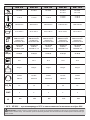
30 ÷ 98 % 30 ÷ 98 % 30 ÷ 98 % 30 ÷ 98 %
30 ÷ 70 %
40 ÷ 98 %
40 ÷ 70 %
1 ÷ 32 °C 1 ÷ 32 °C 1 ÷ 32 °C
1 ÷ 32 °C
1 ÷ 45 °C
3 ÷ 32 °C
3 ÷ 45 °C
350 m³/h-м³/ч 480 m³/h-м³/ч 480 m³/h-м³/ч 1.000 m³/h-м³/ч 1.000 m³/h-м³/ч
*27 l-л / 24 h-ч 41 l-л / 24 h-ч 52 l-л / 24 h-ч 80 l-л / 24 h-ч 86 l-л / 24 h-ч
R1234YF / 310 g-г
GWP-Потенциал
глобального
потепления 1975
R1234YF / 365 g-г
GWP-Потенциал
глобального
потепления 1975
R1234YF / 340 g-г
GWP-Потенциал
глобального
потепления 1975
R1234YF / 700 g-г
GWP-Потенциал
глобального
потепления 1975
R1234YF / 620 g-г
GWP-Потенциал
глобального
потепления 1975
~220-240 V-В
50 Hz-Гц
520 W-Вт / 2,8 A
~220-240 V-В
50 Hz-Гц
610 W-Вт / 3,1 A
~220-240 V-В
50 Hz-Гц
890 W-Вт / 4,4 A
~220-240 V-В
50 Hz-Гц
1.200 W-Вт / 6 A
~220-240 V-В
50 Hz-Гц
1.250 W-Вт / 6 A
dB(A) 46 dB-дБ 53 dB-дБ 53 dB-дБ 50 dB-дБ 50 dB-дБ
8 l-л 12 l-л 12 l-л 12 l-л 12 l-л
30 kg-кг 43 kg-кг 47 kg-кг 66 kg-кг 69 kg-кг
2,6 mPa
LRA 9 A
2,6 mPa
LRA 16 A
2,6 mPa
LRA 21,6 A
2,6 mPa
LRA 20 A
2,6 mPa
LRA 20 A
CO2 Eq 1,2 1,5 1,4 2,8 2,5
GWP 44444
* 30°C - UR 80% - при температуре 30°С и относительной влажности воздуха 80%
IMPORTANT: In order to have a correct function you must use an electrical generator in class G3 or more (frequency variation
±1%, tension variation ±2%). The maximum power of electrical generator must be three time the nominal power of device that you
must connect.
IP IP20 IP20 IP20 IP20 IP20

PICTURES - FIGURE - ABBILDUNGEN - FIGURAS - FIGURES - FIGUREN - FIGU-
RAS - FIGURER - KUVAT - FIGURER - FIGURER - ILUSTRACJE - ИЛЛЮСТРАЦИИ
- OBRÁZKY - ÁBRÁK - SLIKE - ŞEKİLLER - SLIKE - ILIUSTRACIJOS - ATTĒLI -
JOONISED - IMAGINI - OBRÁZKY - СХЕМИ - МАЛЮНКИ - SLIKE - ΕΙΚΟΝΕΣ - 图示
- СУРЕТТЕМЕЛЕР
4
1
2
3
I° II°
III° IV°
5
6
7
5
8888
ALARMPOWER WORKING FULL
ON/OFF HUMIDITY % HOURS
6
1
5
40=240V
I=110V
3
2
DR
26
DR
44
DR
5
2
DR
80
DR
100

PICTURES - FIGURE - ABBILDUNGEN - FIGURAS - FIGURES - FIGUREN - FIGU-
RAS - FIGURER - KUVAT - FIGURER - FIGURER - ILUSTRACJE - ИЛЛЮСТРАЦИИ
- OBRÁZKY - ÁBRÁK - SLIKE - ŞEKİLLER - SLIKE - ILIUSTRACIJOS - ATTĒLI -
JOONISED - IMAGINI - OBRÁZKY - СХЕМИ - МАЛЮНКИ - SLIKE - ΕΙΚΟΝΕΣ - 图示
- СУРЕТТЕМЕЛЕР
4
1
2
3
I° II°
III° IV°
5
6
7
5
8888
ALARMPOWER WORKING FULL
ON/OFF HUMIDITY % HOURS
6
1
5
4
0=240V
I=110V
3
2

4
1
2
3
I° II°
III° IV°
5
6
7
5
8888
ALARMPOWER WORKING FULL
ON/OFF HUMIDITY % HOURS
6
1
5
4
0=240V
I=110V
3
2
PICTURES - FIGURE - ABBILDUNGEN - FIGURAS - FIGURES - FIGUREN - FIGU-
RAS - FIGURER - KUVAT - FIGURER - FIGURER - ILUSTRACJE - ИЛЛЮСТРАЦИИ
- OBRÁZKY - ÁBRÁK - SLIKE - ŞEKİLLER - SLIKE - ILIUSTRACIJOS - ATTĒLI -
JOONISED - IMAGINI - OBRÁZKY - СХЕМИ - МАЛЮНКИ - SLIKE - ΕΙΚΟΝΕΣ - 图示
- СУРЕТТЕМЕЛЕР

4
1
2
3
I° II°
III° IV°
5
6
7
5
8888
ALARMPOWER WORKING FULL
ON/OFF HUMIDITY % HOURS
6
1
5
40=240V
I=110V
3
2
PICTURES - FIGURE - ABBILDUNGEN - FIGURAS - FIGURES - FIGUREN - FIGU-
RAS - FIGURER - KUVAT - FIGURER - FIGURER - ILUSTRACJE - ИЛЛЮСТРАЦИИ
- OBRÁZKY - ÁBRÁK - SLIKE - ŞEKİLLER - SLIKE - ILIUSTRACIJOS - ATTĒLI -
JOONISED - IMAGINI - OBRÁZKY - СХЕМИ - МАЛЮНКИ - SLIKE - ΕΙΚΟΝΕΣ - 图示
- СУРЕТТЕМЕЛЕР

en
it
de
es
fr
nl
pt
da
no
sv
pl
ru
cs
hu
sl
tr
hr
lt
lv
et
ro
sk
bg
uk
bs
el
zh
INDEX
1... INTRODUCTION
2... GENERAL DESCRIPTION OF THE UNIT
3... PRELIMINARY OPERATIONS
4... START-UP
5... MAINTENANCE
6... ALARM LIST
►►►1. INTRODUCTION
►►1.1. INTRODUCTION
The manual is intended for the end user only
in regard to operations that can be performed
with closed panels. The operations that re-
quire to open doors or panels with tools must
only be performed by expert personnel. Each
appliance must be connected to the power
supply via a cable with a power plug supplied
with the unit. For maintenance operations, the
power plug must always be disconnected to
allow the operator to intervene in safe condi-
tions.
If assistance or spare parts are required, read
the identication plate located outside of the
unit to identify the appliance (model and serial
number).
►►1.2. GENERAL SAFETY RULES
The purpose of the manual and of the entire
documentation supplied is to allow both the
installer and operator to correctly perform the
installation, start-up and maintenance of the
equipment, without causing damage to the
personnel in charge and to the unit.
Each appliance is subject to a risk assessment
carried out in compliance with current legisla-
tion, which denes the necessary actions and
implements the protective measures required
to achieve the risk reduction objectives.
All activities regarding the operation and main-
tenance of the unit must be performed:
►Only by properly trained people, who must
implement safe working practices and use
the personal protective equipment appropri-
ate to the specic task performed, based on
their specic qualication.
►Only by properly trained people who have
read and fully understood the manuals,
technical documents and safety documents.
►Use of the appliance must not be allowed to
anyone who is not adequately trained and
skilled.
This manual, the technical documents and
any security documents attached must be
read and stored for the entire lifespan of the
appliance:
CAUTION: This appliance is designed
for use in an indoor environment.
CAUTION: The unit must be connected
to an electrical system that complies with
local electrical safety regulations.
CAUTION: The unit must be placed by
following the dimensions and spaces re-
quired, including the minimum spaces al-
lowed by adjacent structures.
CAUTION: This equipment must always
be connected to earth. We decline any li-
ability for any danger or damage caused if
this requirement is not complied with.
CAUTION: Sharp tools (screwdrivers,
needles or the like) must not be inserted
into the grids or inside any other panel
opening, especially when the unit is open
to remove the lter.
CAUTION: All maintenance and clean-
ing operations on the unit must be per-
formed with the power supply disconnect-
ed. Never remove the front grille or open
any part of the unit without rst discon-
necting the plug from the socket.
CAUTION: Do not use water to clean
the unit. Use a wet cloth to clean the unit.

en
it
de
es
fr
nl
pt
da
no
sv
pl
ru
cs
hu
sl
tr
hr
lt
lv
et
ro
sk
bg
uk
bs
el
zh
Never spray water on the unit and its elec-
trical components.
The equipment must always be kept in a verti-
cal position in order to prevent accidental spill-
age of condensation (water) from the specic
container. It is strictly forbidden to move the
equipment while connected to the power out-
let, as the resulting vibrations and movements
may cause the condensation to leak from the
specic container, thus aecting the electrical
parts.
The unit can only be moved after empty-
ing the condensate tank, and in any case, it
is ALWAYS REQUIRED to remove the plug
from the socket before moving the appli-
ance. Should water be accidentally spilled
on the appliance, the unit must be immedi-
ately turned o and disconnected from the
power supply, and may only be turned on
after eight hours have elapsed.
CAUTION: The equipment contains
R1234yf refrigerant: this gas is ammable.
The amount of charge is indicated in the
data table of this user manual.
Warning, the refrigerant is odourless.
Do not use any means to accelerate the de-
frosting process or for cleaning other than
those recommended by the manufacturer.
The appliance must be placed in a room
that does not have ignition sources con-
tinuously in operation (e.g. open ames, a
gas appliance while running or an electric
heater running).
Do not drill holes into or burn the appli-
ance.
►►1.3. PERSONAL PROTECTIVE
EQUIPMENT
Use the following personal protective equip-
ment during unit use and maintenance opera-
tions:
CLOTHING: Those who carry out main-
tenance or work on the unit in environments
with slippery oors must wear safety shoes
with non-slip soles.
GLOVES: Appropriate gloves must be
worn during cleaning and maintenance opera-
tions. When relling the refrigerant gas, the
use of appropriate gloves is mandatory in or-
der to prevent the risk of freezing.
MASK AND GOGGLES: Masks to protect
the respiratory tract and safety goggles to pro-
tect the eyes must be worn during cleaning
and maintenance operations.
►►1.4. GENERAL SAFETY RULES
The following safety signs, which must be re-
spected, are axed on the unit:
Read the user manual.
Read the technical manual.
Electric shock hazard.
Flammable material hazard.
CAUTION: It is strictly forbidden to re-
move the safety signs on the units.
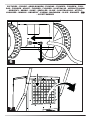
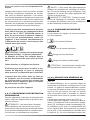
►►►2. GENERAL DESCRIPTION OF
THE UNIT
(FIG. 1)
The dehumidier is an appliance suitable for
controlling the humidity of the room it is placed
in. Dehumidication is carried out via a refrig-
eration cycle which is based on the physical

en
it
de
es
fr
nl
pt
da
no
sv
pl
ru
cs
hu
sl
tr
hr
lt
lv
et
ro
sk
bg
uk
bs
el
zh
principle whereby the air, when it comes into
contact with a cold surface, wets it, releasing
humidity in the form of condensation drops.
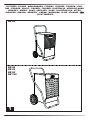
The equipment is made up as follows (FIG. 2):
Air is extracted from the appliance: it passes
through the washable lter (1), the aluminium
coil (evaporator) (2), the hot exchanger (con-
denser) (3), the fan (4) and nally the dehu-
midied air ows out and is recirculated into
the room through the grille. The condensed
water is collected in the tank (5). A micros-
witch stops the appliance when water in the
tank reaches a certain level. An electronic
board (6) manages the correct operation of
the appliance.
This appliance is equipped with a hot gas de-
frost system, which ensures the correct opera-
tion of the dehumidier within the temperature
and humidity range specied in the technical
data table.
►►2.1. REFRIGERANT CIRCUIT
The refrigerant gas used in these units is
R1234yf. The refrigerant circuit is built in com-
pliance with current standards.
Flammable material hazard.
This unit is hermetically sealed and contains
uorinated gas R1234yf GWP (R1234yf) = 4.
►►►3. PRELIMINARY OPERATIONS
►►3.1. REMOVAL OF THE PACKAG-
ING AND ASSEMBLY
Remove the packaging taking care not to dam-
age the unit. Dispose of the packaging prod-
ucts (wood, plastic, cardboard), taking them to
the specialised collection or recycling centres
(follow the local regulations in force).
CAUTION: Depending on the model, as-
semble the appliance, with any handles,
wheels and all relevant hardware (FIG. 3)
housed inside the packaging before commis-
sioning.
►►3.2. INSPECTION
All units are factory assembled and wired
(except for certain components). Upon re-
ceiving the unit, it must be immediately and
thoroughly inspected, checking that it has not
been damaged during transport or that no
parts are missing.
Before use, specically check for any
dents on the external metal panels, including
those in the tank compartment. Also check
that the cable, plug and relevant insulation are
intact. Otherwise, it is FORBIDDEN to con-
nect and start the unit, which must be sent to
an authorised service centre.
►►3.3. OPERATING PRINCIPLES
CAUTION: To ensure correct operation
of the appliance, it is recommended to op-
erate the unit within the limits shown on
the technical data table.
►►3.4. POSITIONING
Set up the appliance to ensure an adequate
air ow.
CAUTION: Make sure that the appliance is
placed in such a way so as to prevent contact
with water.
►►3.5. SERVICE AREA
The hot air expelled by the fan must not be
obstructed. Avoid hot air recirculation between
suction and delivery to prevent compromising
the performance of the unit or even interrupt-
ing normal operation.
CAUTION: The equipment must not be
placed in cramped environments, which do
not allow adequate distribution of the air from
the air outlet grille into the room.
CAUTION: Do not place or hang objects
on the front panel, it may cause damage to
the unit.

en
it
de
es
fr
nl
pt
da
no
sv
pl
ru
cs
hu
sl
tr
hr
lt
lv
et
ro
sk
bg
uk
bs
el
zh
►►3.6. GENERAL INFORMATION
CAUTION: Disconnect the power plug
from the socket before carrying out any main-
tenance operation on the electrical part.
CAUTION: Check that the supply voltage
corresponds to the unit's operating data (volt-
age and frequency) shown on the data plate
on the dehumidier. The appliance is tted
with a power cable for correct operation.
CAUTION: The earthing connection is
mandatory.
►►►4. START-UP
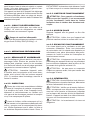
►►4.1. PRELIMINARY CHECKS
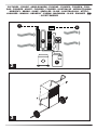
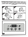
IMPORTANT: For dual voltage mod-
els (...DV), check the position of the trans-
former switch (220-240V / 110-120V). If the
set voltage does not match that supplied
by the mains, the voltage must be adapted
(FIG. 4). Loosen the two lid screw fasten-
ers, shift/press the switch onto the voltage
value supplied and mount the lid again.
CAUTION: Check that the power cord
is properly connected.
CAUTION: Check that all the cover
panels are in the correct position and are
locked via xing screws before commission-
ing.
CAUTION: Always disconnect the
power supply if the appliance is not used for a
long period of time.
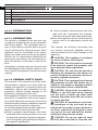
►►4.2. CONTROL PANEL
(FIG. 5)
The units are equipped with a luminous signal-
ling panel that indicates their operating status.
A brief description of their meaning is provided
below.
CONTROL PANEL:
LED:
►POWER LED: This LED is on if the unit is in
the “ON” status, but in stand-by mode (i.e.
the compressor is o).
►ALARM LED: This LED is on when the unit
is in alarm. The display will show the error
message.
►WORKING LED: This LED is on when the
compressor is running. The LED ashes
when the dehumidier is waiting to restart or
is in defrost mode. The LED turns o when
the desired amount of humidity has been
reached in the “ON” status.
►FULL LED: This LED is on when the con-
densate tank is full or if the pump is in alarm.
BUTTONS:
►ON/OFF: To turn on the dehumidier, simply
press the “ON/OFF” button. Based on the
relative humidity set, the appliance starts
working. When the room humidity reaches
the required level, the appliance goes into
stand-by mode and the unit stops, but re-
mains in the “ON” status (POWER LED on).
If the room humidity rises again, exceeding
the previous set point, the dehumidier re-
starts again.
Press the “ON/OFF” button to turn o the
appliance (with the appliance o, the display
continues to indicate the relative humidity in
the environment).
►“-” / “+” (HUMIDITY SET): Press the “-” / “+”
buttons to set the relative humidity desired.
The display will start ashing, showing the
new reference set point. After a few sec-
onds the display stops ashing and the new
humidity set point has been detected by the
electronics.
It is possible to operate the appliance re-
gardless of the degree of humidity present
in the environment. By pressing the “-” but-
ton until the “CONT” message appears on
the display, the appliance will operate con-
tinuously.
►HOURS: Press the “HOURS” button to view
the working hours of the appliance.

en
it
de
es
fr
nl
pt
da
no
sv
pl
ru
cs
hu
sl
tr
hr
lt
lv
et
ro
sk
bg
uk
bs
el
zh
►►4.3. DISCHARGE PIPE CONNEC-
TION (Set-up)
(FIG. 6)
A discharge pipe can be connected to the ap-
pliance. A hose connection with a diameter of
16 mm is tted on the tank.
►►4.4. CONNECTION OF THE CON-
DENSATE PUMP (Optional)
Depending on the model, the appliance
can be set up for the connection of the con-
densate discharge pump.
For a correct connection, disconnect the unit
from the power supply before carrying out any
operation.
For a correct installation of the condensate
pump, refer to the technical manual included
in the optional kit.
►►►5. MAINTENANCE
►►5.1. CHECKS TO BE PERFORMED
BY THE USER
(FIG. 7)
The only maintenance to be carried out by the
user is the cleaning of the air lter, which must
be performed at least once a month.
The cleaning frequency can be increased due
to the dustiness of the working environment of
the appliance.
CAUTION: REMOVE THE FILTER FROM
THE APPLIANCE TO PERFORM CLEANING.
IT IS FORBIDDEN TO PERFORM CLEAN-
ING WITH THE FILTER INSTALLED.
►►5.2. SPARE PARTS
Should it be required to replace one or more
parts during maintenance by specialised op-
erators, this must be done by using original
spare parts only.
If required, request the “spare parts list” from
your vendor, specifying the model and serial
number of the unit.
►►5.3. DISMANTLING THE UNIT
The unit has been designed and built to en-
sure continuous operation. The lifespan of
some components such as the fan and the
compressor depends on their maintenance.
CAUTION: The unit contains sub-
stances and components dangerous for the
environment (electronic components, refriger-
ant gas and oils). At the end of its useful life, in
the event of dismantling the unit, the operation
must be carried out by specialised refrigerat-
ing personnel.
The unit must be sent to specic special-
ised centres for the collection and disposal of
equipment containing dangerous substances.
The refrigerant uid and the lubricating oil
contained in the circuit must be recovered,
in accordance with the regulations in force in
your country.

en
it
de
es
fr
nl
pt
da
no
sv
pl
ru
cs
hu
sl
tr
hr
lt
lv
et
ro
sk
bg
uk
bs
el
zh
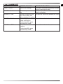
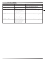
►►►6. ALARM LIST
ALARM POSSIBLE CAUSE POSSIBLE SOLUTION
FULL + “FULL“ Tank full or missing The alarm is reset automatically by emp-
tying or inserting the tank
ALARM + “Lo t“ Room temperature too
low
Room temperature conditions not suit-
able for operation
ALARM + “Prob“ Humidity probe malfunc-
tion. In any case, the
unit continues to function
Contact the authorised assistance centre
ALARM + “Pro3“ Room temperature
probe malfunction.
The dehumidier goes
into stand-by mode
Contact the authorised assistance centre
ALARM + “dEFr“ Defrost thermostat mal-
function.
The dehumidier goes
into stand-by mode
Contact the authorised assistance centre

en
it
de
es
fr
nl
pt
da
no
sv
pl
ru
cs
hu
sl
tr
hr
lt
lv
et
ro
sk
bg
uk
bs
el
zh
INDEX
1... INTRODUCTION
2... DESCRIPTION GÉNÉRALE DE L’UNITÉ
3... OPÉRATIONS PRÉLIMINAIRES
4... DÉMARRAGE
5... ENTRETIEN
6... LISTE DES ALARMES
►►►1. INTRODUCTION
►►1.1. INTRODUCTION
Le manuel ne s’adresse à l’utilisateur nal que
pour les opérations réalisables les panneaux
étant fermés. Les opérations qui nécessitent d’ou-
vrir les portes ou les panneaux avec des outils
ne doivent être eectuées que par un personnel
expert. Chaque appareil doit être branché à l’ali-
mentation électrique par un câble doté d’une che
d’alimentation fournie avec l’unité. Pour les opé-
rations d’entretien, il faut toujours débrancher la
che d’alimentation pour que l’opérateur puisse
intervenir en toute sécurité.
Pour identier l’appareil (modèle et numéro de
série), en cas de demande d’assistance ou de
pièces de rechange, il faut lire la plaque d’identi-
cation xée à l’extérieur de l’unité.
►►1.2. CONSIGNES DE SÉCURITÉ
GÉNÉRALES
Ce manuel ainsi que l’ensemble de la documen-
tation fournie ont pour but de mettre l’installateur
et l’opérateur dans les conditions d’eectuer cor-
rectement l’installation, la mise en marche et l’en-
tretien de l’équipement, sans provoquer de dom-
mages au personnel préposé ni à l’unité.
Chaque appareil est soumis à une évaluation des
risques eectuée conformément aux normes en
vigueur, qui dénit les opérations nécessaires et
met en œuvre les mesures de protection néces-
saires pour atteindre les objectifs de réduction du
risque.
Toutes les activités relatives au fonctionnement et
à l’entretien de l’unité ne doivent être eectuées
que :
►Par des personnes dûment instruites qui doivent
adopter des pratiques de travail sûres et utili-
ser les équipements de protection individuelle
adaptés à la tâche spécique qu’elles eec-
tuent, en fonction de leur qualication.
►Par des personnes dûment instruites, qui ont
lu entièrement et compris les manuels, les do-
cuments techniques et les documents de sécu-
rité.
►L’utilisation de l’appareil doit être refusée à toute
personne qui n'est pas correctement formée et
compétente.
Le présent manuel, les documents techniques et
les documents de sécurité éventuellement joints
doivent être lus et conservés pendant toute la vie
de l’appareil :
ATTENTION : Cet appareil est conçu pour
être utilisé à l’intérieur.
ATTENTION : L’unité doit être branchée
à une installation électrique conforme aux
normes de sécurité électrique locales.
ATTENTION : L’unité doit être mise en place
en respectant ses dimensions et les espaces
nécessaires, y compris les espaces minimums
que laissent les structures adjacentes.
ATTENTION : Cet appareil doit toujours
être branché à une prise de terre ; le fabricant
décline toute responsabilité en cas de danger
ou de dommage si cette prescription n’est pas
respectée.
ATTENTION : Il ne faut pas introduire d’ou-
tils pointus (tournevis, aiguilles, etc.) dans les
grilles ou dans toute autre ouverture des pan-
neaux, surtout lorsque l’unité est ouverte pour
enlever le ltre.
ATTENTION : Chaque intervention d’entre-
tien et de nettoyage sur l’unité doit être eec-
tuée en débranchant l’alimentation électrique.
Il ne faut jamais enlever la grille avant ou
ouvrir n’importe quelle partie de l’unité sans
avoir débranché la che de la prise.
ATTENTION : Il ne faut pas utiliser d’eau
pour nettoyer l’unité. La nettoyer en utilisant
un chion humide. Il ne faut jamais pulvériser

en
it
de
es
fr
nl
pt
da
no
sv
pl
ru
cs
hu
sl
tr
hr
lt
lv
et
ro
sk
bg
uk
bs
el
zh
d’eau sur l’unité ni sur ses composants élec-
triques.
L’appareil doit toujours rester en position verticale
n d’éviter l’écoulement accidentel de conden-
sats (eau) du récipient spécique. Il est absolu-
ment interdit de déplacer l'équipement lorsqu'il est
branché à la prise de courant, car les vibrations et
les mouvements qui en résultent pourraient faire
s'écouler les condensats du récipient spécique,
ce qui pourrait aecter les parties électriques.
L’unité ne peut être manutentionnée qu’après
avoir vidé le réservoir des condensats et dans
tous les cas, IL FAUT TOUJOURS enlever la
che de la prise avant de déplacer l’appareil.
Si de l’eau est accidentellement versée sur
l’appareil, il faut l’éteindre immédiatement et
le débrancher du secteur, il ne pourra pas être
rallumé avant huit heures.
ATTENTION : L’équipement contient du gaz
réfrigérant R1234yf : ce gaz est inammable.
La quantité de charge est indiquée dans le
tableau des données de cette notice d’utilisa-
tion.
Faites attention, le réfrigérant est inodore.
N'utilisez aucun moyen pour accélérer le pro-
cessus de dégivrage ou pour le nettoyage
autre que ceux recommandés par le fabricant.
L'appareil doit être placé dans un local qui
ne comporte pas de sources d'inammation
en fonctionnement continu (par exemple des
ammes nues,un appareil à gaz ou un chauf-
fage électrique en marche).
Ne pas percer ou brûler l’appareil.
►►1.3. ÉQUIPEMENTS DE PROTECTION
PERSONNELLE
Pour les opérations d’utilisation et d’entretien des
unités, utiliser les équipements de protection per-
sonnelle suivants :
VÊTEMENTS : Les techniciens d’entretien
ou les opérateurs qui interviennent sur l’unité
doivent porter des chaussures de sécurité dotées
d’une semelle antidérapante s’ils travaillent dans
un local avec un revêtement de sol glissant.
GANTS : Il faut porter des gants appropriés
pendant les opérations de nettoyage et d’entre-
tien. En cas de recharge du gaz réfrigérant, il est
obligatoire de porter des gants appropriés an
d’éviter le risque de gel.
MASQUE ET LUNETTES : Pendant les opé-
rations de nettoyage et d’entretien, il faut porter
un masque de protection des voies respiratoires
et des lunettes de protection des yeux.
►►1.4. CONSIGNES DE SÉCURITÉ
GÉNÉRALES
L’unité reporte les signaux de sécurité suivants
qu’il faut respecter :
Lire le manuel utilisateur.
Lire le manuel technique.
Danger de choc électrique.
Danger de matériau inammable.
ATTENTION : Il est strictement interdit d’enle-
ver la signalétique de sécurité sur les unités.
►►►2. DESCRIPTION GÉNÉRALE DE
L’UNITÉ
(FIG. 1)
Le déshumidicateur est un appareil adapté au
contrôle de l’humidité de l’environnement où il est
installé. La phase de déshumidication exploite
un cycle de réfrigération basé sur le principe phy-
sique qui fait que lorsque l'air entre en contact
avec une surface froide, il l'humidie, en libérant
de l'humidité sous forme de gouttes de conden-
sation.
L’appareil est composé comme suit (FIG. 2) :
L'air est aspiré par l’appareil, il traverse le ltre la-
vable (1), le serpentin froid en aluminium (évapo-
rateur) (2), l'échangeur chaud (condensateur) (3),
le ventilateur (4) et, enn, l'air déshumidié sort
et est expulsé dans l'environnement en passant
par la grille. L'eau condensée est recueillie dans
le réservoir (5). Un micro-interrupteur arrête l'ap-

en
it
de
es
fr
nl
pt
da
no
sv
pl
ru
cs
hu
sl
tr
hr
lt
lv
et
ro
sk
bg
uk
bs
el
zh
pareil lorsque l'eau du réservoir atteint un certain
niveau. Une carte électronique (6) gère le fonc-
tionnement correct de l’appareil.
Cet appareil est doté d’un dispositif de dégivrage
à gaz chaud qui garantit le fonctionnement correct
du déshumidicateur dans une plage de tempé-
rature et d’humidité précisée dans le tableau des
données techniques.
►►2.1. CIRCUIT DE RÉFRIGÉRATION
Le gaz réfrigérant utilisé dans ces unités est le
R1234yf. Le circuit de réfrigération est réalisé
conformément aux normes en vigueur.
Danger de matériau inammable.
Cette unité est hermétiquement scellée et contient
du gaz uoré R1234yf GWP (R1234yf) = 4.
►►►3. OPÉRATIONS PRÉLIMINAIRES
►►3.1. DÉBALLAGE ET ASSEMBLAGE
Ôter l’emballage en faisant attention à ne pas en-
dommager l’unité. Éliminer les produits de l’em-
ballage (bois, plastique, carton) en les remettant
à un centre de collecte ou de recyclage spécialisé
(respecter les normes locales en vigueur).
ATTENTION : Assembler l’appareil, selon
le modèle, avec les poignées et les roues éven-
tuelles ainsi qu’avec tous les boulons respectif
(FIG. 3), contenus dans l’emballage, avant de le
mettre en marche.
►►3.2. INSPECTION
Toutes les unités sont assemblées et câblées
en usine (à l’exception de certains composants).
À la réception de l’unité, il faut l’inspecter immé-
diatement et méticuleusement en vériant qu’il
n’ait pas subi de dommages pendant le transport
ou qu’il ne manque pas de pièces.
Avant de l’utiliser, vérier notamment qu’il n’y
ait pas bosses sur les panneaux métalliques exté-
rieurs, y compris ceux du compartiment du réser-
voir. Vérier également que le câble, la che et
les isolations respectives soient intacts. Sinon, IL
EST INTERDIT de brancher et de démarrer l’unité
qu’il faut envoyer à un centre d’assistance agréé.
►►3.3. LIMITES DE FONCTIONNEMENT
ATTENTION : Pour garantir un fonctionne-
ment correct de l’appareil, il est recommandé
de faire fonctionner l’unité dans les limites
indiquées dans le tableau des données tech-
niques.
►►3.4. MISE EN PLACE
Disposer l’appareil an de garantir un ux d’air
adéquat.
ATTENTION : Veiller à ce que l’appareil soit
placé de manière à éviter le contact avec l’eau.
►►3.5. ESPACE DE FONCTIONNEMENT
L’air chaud éjecté par le ventilateur ne doit pas
rencontrer d’obstacles. Éviter tout phénomène
de recirculation de l’air chaud entre aspiration et
refoulement sous peine d’annulation des perfor-
mances de l’unité ou même de l’interruption du
fonctionnement normal.
ATTENTION : L’équipement ne doit pas être
placé dans des espaces étroits qui ne permettent
pas une diusion adéquate, dans la pièce, de l’air
provenant de la grille de sortie de l’air.
ATTENTION : Ne pas poser ou suspendre
d’objets au panneau avant, cela peut causer des
dommages à l’unité.
►►3.6. GÉNÉRALITÉS
ATTENTION : Avant d’eectuer toute interven-
tion d’entretien sur la partie électrique, débrancher
la che d’alimentation de la prise.
ATTENTION : Vérier que la tension d’alimen-
tation corresponde aux données de fonctionne-
ment de l’unité (tension et fréquence) indiquées
sur la plaque des données à bord du déshumidi-
cateur. L’appareil est doté d’un câble d’alimenta-
tion pour son fonctionnement correct.
ATTENTION : Le branchement à la terre est
obligatoire.

en
it
de
es
fr
nl
pt
da
no
sv
pl
ru
cs
hu
sl
tr
hr
lt
lv
et
ro
sk
bg
uk
bs
el
zh
►►►4. DÉMARRAGE
►►4.1. CONTRÔLES PRÉLIMINAIRES
IMPORTANT : Sur les modèles à double
voltage (...DV), contrôler la position de l'inter-
rupteur de changement de tension (220-240V /
110-120V). Si la tension congurée ne corres-
pond pas à celle fournie par le réseau, il est
nécessaire d'intervenir pour adapter la tension
(FIG. 4). Dévisser les deux vis de xation du
couvercle, déplacer/presser l’interrupteur sur
la valeur de tension fournie et remonter le cou-
vercle.
ATTENTION : Vérier que le câble d’ali-
mentation soit branché correctement.
ATTENTION : Avant de procéder à la mise
en service, contrôler que tous les panneaux de
couverture soient placés dans la bonne position
et qu’ils soient bloqués avec des vis de xation.
ATTENTION : Si l’appareil n’est pas uti-
lisé pendant une longue période, il faut toujours
débrancher la prise d’alimentation électrique.
►►4.2. PANNEAU DE CONTRÔLE
(FIG. 5)
Les unités sont dotées d’un panneau lumineux de
signalisation qui indique l’état de fonctionnement
de l’unité.
Une description rapide de leur signication est
fournie ci-après.
PANNEAU DE CONTRÔLE :
LED :
►POWER LED : Cette LED est allumée si l’uni-
té est dans l’état « ON » mais en mode veille
(c’est-à-dire que le compresseur est éteint).
►ALARM LED : Cette LED est allumée quand
l’unité est en alarme. L’écran ache le message
d’erreur.
►WORKING LED : Cette LED est allumée quand
le compresseur est en marche. La LED clignote
quand le déshumidicateur est en attente de
redémarrage ou en cours de dégivrage. La LED
s’éteint quand la quantité d’humidité désirée a
été atteinte dans l’état « ON ».
►FULL LED : Cette LED est allumée quand le ré-
servoir des condensats est plein ou si la pompe
est en alarme.
BOUTONS :
►ON/OFF : Pour allumer le déshumidicateur, il
sut de presser le bouton « ON/OFF ». Selon
l’humidité relative congurée, l’appareil com-
mence à travailler. Lorsque l’humidité ambiante
atteint le niveau requis, l’appareil va en mode
veille et l’unité s’arrête mais reste dans l’état
« ON » (POWER LED allumée). Si l’humidité
ambiante remonte, en dépassant le point de
consigne qui a été conguré, le déshumidica-
teur redémarre.
Presser le bouton « ON/OFF » pour éteindre
l’appareil (lorsque l’appareil est éteint, l’écran
continue à indiquer l’humidité relative présente
dans le local).
►« - »/ « + » (RÉGLAGE HUMIDITÉ) : Presser
les boutons « - »/ « + » permet de congurer
l’humidité relative désirée. L’écran commence
à clignoter en achant le nouveau point de
consigne de référence. Après quelques se-
condes, l’écran cesse de clignoter et le nouveau
point de consigne de l’humidité a été détecté
par l’électronique.
Il est possible de faire fonctionner l’appareil
indépendamment du degré d’humidité dans
l’environnement. Presser le bouton « - » jusqu’à
visualiser le message « CONT » à l’écran, l’ap-
pareil fonctionne en continu.
►HOURS : Presser le bouton « HOURS » pour
acher les heures de fonctionnement de l’ap-
pareil.
►►4.3. BRANCHEMENT D’UN TUYAU
D’ÉVACUATION (agencement)
(FIG. 6)
Il est possible de brancher un tuyau d’évacuation
à l’appareil. Il y a un raccord de tuyau de 16 mm
de diamètre sur le réservoir.
►►4.4. BRANCHEMENT DE LA POMPE
À CONDENSATS (en option)
Selon le modèle, l’appareil pet être doté d’un
agencement pour brancher la pompe d’évacua-
tion des condensats.
Pour eectuer un branchement correct, débran-
cher l’unité de l’alimentation électrique avant d’ef-
fectuer toute opération.
Pour installer correctement la pompe d’évacuation
des condensats, consulter le manuel technique
inséré dans le kit en option.

en
it
de
es
fr
nl
pt
da
no
sv
pl
ru
cs
hu
sl
tr
hr
lt
lv
et
ro
sk
bg
uk
bs
el
zh
►►►5. ENTRETIEN
►►5.1. CONTRÔLES À LA CHARGE DE
L’UTILISATEUR
(FIG. 7)
La seule opération d’entretien à la charge de l’uti-
lisateur est le nettoyage du ltre à air, à eectuer
au moins une fois par mois.
La fréquence de ce nettoyage peut être augmen-
tée en raison de la quantité de poussière de l’envi-
ronnement de travail de l’appareil.
ATTENTION : IL FAUT ENLEVER LE FILTRE
DE L’APPAREIL POUR EFFECTUER LE NET-
TOYAGE. IL EST INTERDIT D’EFFECTUER LE
NETTOTAGE LE FILTRE ÉTANT INSTALLÉ.
►►5.2. PIÈCES DE RECHANGE
Pendant les opérations d’entretien à la charge des
opérateurs spécialisés, s’il faut remplacer une ou
plusieurs pièces, il ne faut utiliser que des pièces
de rechange originales.
En cas de besoin, demander la « liste des pièces
de rechange » en précisant le modèle et le numé-
ro de série de l’unité.
►►5.3. DÉMANTÈLEMENT DE L’UNITÉ
L’unité a été conçue et fabriquée pour garantir
un fonctionnement continu. La durée de certains
composants tels le ventilateur et le compresseur
dépend de l’entretien auquel ils ont été soumis.
ATTENTION : L’unité contient des subs-
tances et des composants dangereux pour l’en-
vironnement (composants électroniques, gaz
réfrigérant et huiles). À la n de sa vie utile, le
démantèlement de l’unité doit être eectué par un
installateur frigoriste spécialisé.
L’unité doit être remise à un centre spécialisé pour
la collecte et l’élimination des équipements conte-
nant des substances dangereuses. Le uide de
réfrigération et l’huile lubriante du circuit doivent
être récupérés, conformément aux normes en vi-
gueur dans votre pays.

en
it
de
es
fr
nl
pt
da
no
sv
pl
ru
cs
hu
sl
tr
hr
lt
lv
et
ro
sk
bg
uk
bs
el
zh
►►►6. LISTE DES ALARMES
ALARME CAUSE POSSIBLE SOLUTION POSSIBLE
FULL + « FULL » Réservoir plein ou absent L’alarme se réinitialise automatiquement en
vidant ou en insérant le réservoir
ALARM + « Lo t » Température ambiante trop
basse
Conditions de température ambiante non
adaptées au fonctionnement
ALARM + « Prob » Dysfonctionnement de la
sonde d’humidité. Dans
tous les cas, l’unité conti-
nue à fonctionner
Contacter le centre d'assistance agréé
ALARM + « Pro3 » Dysfonctionnement de
la sonde de température
ambiante.
Le déshumidicateur se
place en mode veille
Contacter le centre d'assistance agréé
ALARM + « dEFr » Dysfonctionnement du
thermostat de dégivrage.
Le déshumidicateur se
place en mode veille
Contacter le centre d'assistance agréé

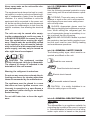
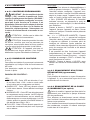
ELECTRIC SYSTEM - IMPIANTO ELETTRICO - ELEKTRISCHE ANLAGE - INSTA-
LACIÓN ELÉCTRICA - INSTALLATION ELECTRIQUE - ELEKTRISCHE INSTAL-
LATIE - SISTEMA ELÉTRICO - EL-ANLÆG - SÄHKÖLAITTEISTO - ELEKTRISK
ANLEGG - ELANORDNING - INSTALACJA ELEKTRYCZNA - ЭЛЕКТРОПРОВОДКА
- ELEKTRICKÉ ZAŘÍZENÍ - ELEKTROMOS RENDSZER - ELEKTRIČNA NAPELJA-
VA - ELEKTRİK TESİSATI - ELEKTRIČNI UREĐAJ - ELEKTROS SISTEMA - ELEK-
TRISKĀ SISTĒMA - ELEKTRISÜSTEEM - INSTALAŢIA ELECTRICĂ - ELEKTRICKÉ
ZARIADENIE - ЕЛЕКТРИЧЕСКА ИНСТАЛАЦИЯ - ЕЛЕКТРИЧНЕ ОБЛАДНАННЯ -
ELEKTRIČNI UREĐAJ - ΗΛΕΚΤΡΙΚΗ ΕΓΚΑΤΑΣΤΑΣΗ - 电路系统 - ЭЛЕКТРЖЕЛІСІ
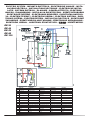
5Electrical scheme
Electrical scheme single voltage version
DR
26
DR
44
D
R 5
2
DR
80
DR
100
ENGLISH
ITALIANO
DEUTSCH
FRANÇAIS
ESPAÑOL
1 COMPRESSOR COMPRESSORE KOMPRESSOR COMPRESSUR
COMPRESOR
2
MOTORFAN VENTILATORE VENTILATOR VENTILATEUR
VENTILADOR
3 ELECTROVALVE ELETTROVALVOLA MAGNETVENTIL ÉLECTROVANNE
ELECTROVÁLVULA
4 PLUG SPINA
ELEKTRISCHER
STECKER
PRISE ÉLECTRIQUE
ENCHUFE ELECTRICO
5 ELECTRONIC BOARD SCHEDA ELETTRONICA
ELEKTRONISCHE
KARTE
CARTE ÉLECTRONIQUE
PLACA ELECTRONICA
6
DISPLAY
DISPLAY
ANZEIGE
AFFICHEUR
PANTALLA
7 TANK SENSOR SENSORE TANICA TANK SENSOR
CAPTEUR DE
RÉSERVOIR
TANQUE SENSOR
8 PUMP CONNECTOR CONNETTORE POMPA PUMPENANSCHLUSS
CONNECTEUR DE
POMPE
CONECTOR BOMBA
9
AUTOTRANSFORMER AUTOTRASFORMATORE SPARTRANSFORMATOR AUTOTRANSFORMATEUR
AUTOTRANSFORMADOR
10
PUMP
POMPA
PUMPE
POMPE
BOMBA
11
VOLTAGE SELECTOR SELETTORE TENSIONE SPANNUNGSAUSWAHL SÉLECTEUR DE TENSION
SELECTOR DE VOLTAJE
BROWN
MARRONE
BRAUN
MARRON
MARRON
BLUE BLU BLAU BLEU
AZUL
BLACK
NERO
SCHWARZ
NOIR
NEGRO
RED ROSSO ROT ROUGE
ROJO
GREY GRIGIO GRAU GRIS
GRIS
ORANGE ARANCIONE ORANGE ORANGE
NARANJA
La pagina si sta caricando...
La pagina si sta caricando...
La pagina si sta caricando...
-
 1
1
-
 2
2
-
 3
3
-
 4
4
-
 5
5
-
 6
6
-
 7
7
-
 8
8
-
 9
9
-
 10
10
-
 11
11
-
 12
12
-
 13
13
-
 14
14
-
 15
15
-
 16
16
-
 17
17
-
 18
18
-
 19
19
-
 20
20
-
 21
21
-
 22
22
-
 23
23


Dantherm DR26 Mobile electric dehumidifiers Manuale utente
- Tipo
- Manuale utente
in altre lingue
Documenti correlati
Altri documenti
-
Master ACD 137 Manuale del proprietario
-
Master DH 26 44 62 92 100 44DV 62DV (R1234yf) E2020 Manuale del proprietario
-
-
-
-
Master DHP 45 DHP 65 Manuale del proprietario
-