
Betriebsanleitung | Operating instructions | Notice d’instruction
Istruzioni per l'uso | Instrucciones de servicio | Bruksanvisning | Инструкция по
эксплуатации
R412012414-BAL-001-AF
2022-03; Replaces: 2016-09
DE/EN/FR/IT/ES/SV/RU
AVENTICS™ ST4-2P
Sensor mit und ohne I/O-Link
Sensor with and without IO-Link
Capteur avec et sans lien E/S
Sensore con e senza I/O-Link
Sensor con y sin enlace E/S
Sensor med och utan I/U-länk
Датчик с I/O-Link и без I/O-Link

AVENTICS™ ST4-2P | R412012414-BAL-001-AF | Deutsch 2
Inhaltsverzeichnis
1 Zu dieser Anleitung ........................................................................................................................................................................................................... 3
1.1 Weiterführende Dokumentation....................................................................................................................................................................................... 3
2 Zu Ihrer Sicherheit ............................................................................................................................................................................................................. 3
2.1 Bestimmungsgemäßer Gebrauch ..................................................................................................................................................................................... 3
2.2 Nicht bestimmungsgemäßer Gebrauch ............................................................................................................................................................................ 3
2.3 Qualifikation des Personals ............................................................................................................................................................................................... 3
2.4 Darstellung von Informationen ......................................................................................................................................................................................... 3
2.4.1 Warnhinweise .................................................................................................................................................................................................... 3
2.4.2 Symbole............................................................................................................................................................................................................. 3
2.5 Das müssen Sie beachten.................................................................................................................................................................................................. 3
2.5.1 Allgemeine Hinweise:......................................................................................................................................................................................... 3
2.5.2 Bei der Montage:................................................................................................................................................................................................ 3
2.5.3 Während des Betriebs: ....................................................................................................................................................................................... 3
3 Gerätebeschreibung.......................................................................................................................................................................................................... 3
4 Lieferumfang..................................................................................................................................................................................................................... 3
5 Montage und Inbetriebnahme........................................................................................................................................................................................... 4
5.1 Sensor ST4-2P mechanisch justieren................................................................................................................................................................................. 4
5.2 Sensor ST4-2P elektronisch justieren................................................................................................................................................................................. 4
5.3 Schaltpunkte speichern..................................................................................................................................................................................................... 5
5.4 Gespeicherte Schaltpunkte kontrollieren .......................................................................................................................................................................... 5
6 Pflege und Wartung .......................................................................................................................................................................................................... 5
7 Entsorgung........................................................................................................................................................................................................................ 5
8 Daten zur Konfiguration mit I/O-Link ................................................................................................................................................................................. 5
8.1 Physikalische Schicht ........................................................................................................................................................................................................ 5
8.2 Prozessdaten .................................................................................................................................................................................................................... 5
8.3 Direkte Parameter-Seite.................................................................................................................................................................................................... 6
8.4 Servicedaten (I/O-Link) ..................................................................................................................................................................................................... 6
9 Technische Daten .............................................................................................................................................................................................................. 6

1 Zu dieser Anleitung
Die Anleitung enthält wichtige Informationen, um den Sensor ST4-2P sicher und
sachgerecht zu installieren und zu bedienen.
uLesen Sie diese Anleitung vollständig, bevor Sie mit dem Sensor ST4-2P arbei-
ten. Siehe insbesondere auch g2.Zu Ihrer Sicherheit.
1.1 Weiterführende Dokumentation
Der Sensor ST4-2P ist eine Anlagenkomponente. Beachten Sie auch die Anlagen-
dokumentation des Anlagenherstellers.
2 Zu Ihrer Sicherheit
Der Sensor ST4-2P wurde entsprechend dem heutigen Stand der Technik und
den anerkannten sicherheitstechnischen Regeln hergestellt. Trotzdem besteht
die Gefahr von Personen- und Sachschäden, wenn Sie die folgenden allgemeinen
Sicherheitshinweise und die Warnhinweise vor Handlungsanweisungen in dieser
Anleitung nicht beachten.
1. Lesen Sie daher diese Anleitung gründlich und vollständig, bevor Sie mit dem
Sensor ST4-2P arbeiten.
2. Bewahren Sie die Anleitung so auf, dass Sie jederzeit für alle Benutzer zugäng-
lich ist.
3. Geben Sie den Sensor ST4-2P an Dritte stets zusammen mit der Bedienungs-
anleitung weiter.
2.1 Bestimmungsgemäßer Gebrauch
1. Setzen Sie den Sensor ST4-2P ausschließlich im gewerblichen Bereich ein.
2. Setzen Sie den Sensor ST4-2P nur bei AVENTICS Handhabungsgeräten mit C-
Nut ein.
3. Halten Sie die in den technischen Daten genannten Leistungsgrenzen ein.
Der bestimmungsgemäße Gebrauch schließt auch ein, dass Sie diese Anleitung
und insbesondere das Kapitel g2.Zu Ihrer Sicherheit gelesen und verstanden ha-
ben.
2.2 Nicht bestimmungsgemäßer Gebrauch
Als nicht bestimmungsgemäßer Gebrauch gilt, wenn Sie den Sensor ST4-2P
• außerhalb der Anwendungsgebiete verwenden, die in dieser Anleitung ge-
nannt werden,
• unter Betriebsbedingungen verwenden, die von den in dieser Anleitung be-
schriebenen abweichen.
2.3 Qualifikation des Personals
Die Montage und Inbetriebnahme erfordert grundlegende elektrische und pneu-
matische Kenntnisse. Die Montage und Inbetriebnahme darf daher nur von einer
Elektro- oder Pneumatikfachkraft oder von einer unterwiesenen Person unter der
Leitung und Aufsicht einer Fachkraft erfolgen. Eine Fachkraft ist, wer aufgrund
seiner fachlichen Ausbildung, seiner Kenntnisse und Erfahrungen sowie seiner
Kenntnisse der einschlägigen Bestimmungen die ihm übertragenen Arbeiten be-
urteilen, mögliche Gefahren erkennen und geeignete Sicherheitsmaßnahmen
treffen kann. Eine Fachkraft muss die einschlägigen fachspezifischen Regeln ein-
halten.
2.4 Darstellung von Informationen
2.4.1 Warnhinweise
In dieser Dokumentation stehen Warnhinweise vor einer Handlungsabfolge, bei
der die Gefahr von Personen- oder Sachschäden besteht. Die beschriebenen
Maßnahmen zur Gefahrenabwehr müssen eingehalten werden.
Aufbau von Warnhinweisen
SIGNALWORT
Art und Quelle der Gefahr
Folgen bei Nichtbeachtung
uMaßnahmen zur Gefahrenabwehr
Bedeutung der Signalwörter
WARNUNG
Möglicherweise drohende Gefahr für das Leben und die Gesundheit von Perso-
nen.
Das Nichtbeachten dieser Hinweise kann schwere gesundheitliche Auswirkun-
gen zur Folge haben, bis hin zum Tod.
VORSICHT
Möglicherweise gefährliche Situation.
Das Nichtbeachten dieser Hinweise kann leichte Verletzungen zur Folge haben
oder zu Sachbeschädigungen führen.
ACHTUNG
Möglichkeit von Sachbeschädigungen oder Funktionsstörungen.
Das Nichtbeachten dieser Hinweise kann Sachbeschädigungen oder Funktions-
störungen zur Folge haben, jedoch keine Personenschäden.
2.4.2 Symbole
Empfehlung für den optimalen Einsatz unserer Produkte.
Beachten Sie diese Informationen, um einen möglichst reibungslosen
Betriebsablauf zu gewährleisten.
2.5 Das müssen Sie beachten
2.5.1 Allgemeine Hinweise:
• Beachten Sie die Vorschriften zur Unfallverhütung und zum Umweltschutz im
Verwenderland und am Arbeitsplatz.
• Sie dürfen das Gerät grundsätzlich nicht verändern oder umbauen.
• Verwenden Sie das Gerät ausschließlich im Leistungsbereich, der in den tech-
nischen Daten angegeben ist.
• Der Sensor ST4-2P ist kein Sicherheitsbauteil nach Maschinenrichtlinie.
• Verwenden Sie eine Stromquelle gemäß
IEC/DINEN60204-1.
2.5.2 Bei der Montage:
• Schalten Sie den relevanten Anlagenteil drucklos und spannungsfrei, bevor
Sie das Gerät montieren bzw. Stecker anschließen oder ziehen.
• Sichern Sie die Anlage gegen Wiedereinschalten. Hängen Sie während der
Montage Warnschilder an die Hauptschalter, die vor dem Wiedereinschalten
warnen.
• Vermeiden Sie ferritische Bauteile im unmittelbaren Umfeld des Sensors
ST4-2P.
2.5.3 Während des Betriebs:
• Nehmen Sie den Sensor erst in Betrieb, wenn er komplett montiert und kor-
rekt angeschlossen ist, und nachdem Sie ihn getestet haben.
3 Gerätebeschreibung
Der Sensor ST4-2P ist ein magnetischer Positionssensor mit zwei Schaltpunkten.
Er dient zur Endlagenabfrage sowie Zwischenpositionserkennung an Pneumatik-
zylindern. Der Sensor ST4-2P erfasst die Positionen berührungslos.
Schaltpunkte können für beliebige Kolbenpositionen mit Hilfe des Teach-Tasters
exakt eingestellt werden. Siehe g5.3Schaltpunkte speichern.
4 Lieferumfang
• 1x Betriebsanleitung
• 1x Sensor
• 1x Sechskant-Schraubendreher SW1,3
AVENTICS™ ST4-2P | R412012414-BAL-001-AF | Deutsch 3

5 Montage und Inbetriebnahme
WARNUNG
Verletzungsgefahr durch Montage unter Druck!
Wenn Sie den Druck vor Montagebeginn nicht abschalten, können Sie sich ver-
letzen und das Gerät oder Anlagenteile beschädigen.
uSchalten Sie den relevanten Anlagenteil drucklos, bevor Sie das Produkt
montieren.
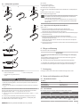
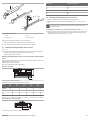
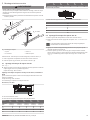
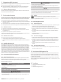
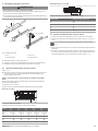
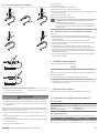
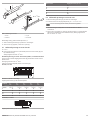
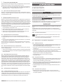
MA = 8+5
Ncm
1
2
3
4
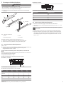
Abb.1: Montage des Sensors
1 Sensor 2 C-Nut
3 Befestigungsschraube 4 Sensormitte
Benötigtes Werkzeug: Sechskant-Schraubendreher SW1,3.
1. Stellen Sie Ihr Handhabungsgerät auf die Mitte des Arbeitshubes.
2. Setzen Sie den Sensor (1) von oben, mittig in die C-Nut (2) ein.
5.1 Sensor ST4-2P mechanisch justieren
Siehe gAbb.1
uRichten Sie den Sensor auf die Mitte Ihres Messbereiches aus (Sensormitte (4)
beachten) und schrauben Sie die Befestigungsschraube (3) fest.
Anzugsdrehmoment: MA=8+5Ncm.
Sensor ST4-2P mechanisch justieren bei Zylindern, Serie MSC und
RCM
Richten Sie die Sensormitte auf die Hubmitte (X) der Aktuatoren aus und schrau-
ben Sie die Befestigungsschraube fest.
Anzugsdrehmoment: MA=8+5Ncm.
Beachten Sie außerdem bei der Montage folgende Vorgaben:
Minischlitten, Serie MSC
X
Der Minischlitten muss eingefahren sein.
Die Hubmitte (X) wird gemessen ab der Frontplatte.
Hub 10
mm
20
mm
30
mm
40
mm
50
mm
MSC-
Varianten
Hubmitte (X) Hubmitte (X) Hubmitte (X) Hubmitte (X) Hubmitte (X)
844 39 44 49 54
12 65 60 55 60 65
16 63 58 53 58 64
20 69 64 59 65 68
25 80 75 70 75 82
Drehmodul, Serie RCM
X
Die Hubmitte (X) wird gemessen ab dem Abschlussdeckel.
RCM-Varianten Hubmitte (X) in mm
635,5
838,5
12 54
16 58
20 62
25 82,5
5.2 Sensor ST4-2P elektronisch justieren
1. Stellen Sie Ihr Handhabungsgerät auf die Mitte des Arbeitshubes.
2. Legen Sie am Sensor eine geeignete Betriebsspannung an. Siehe g9.Techni-
sche Daten.
Der Sensor muss außerhalb beeinflussender Magnetfelder eingeschal-
tet werden.
3. Drücken Sie den Teach-Taster 8-10s bis beide LED’s abwechselnd blinken.
4. Setzen Sie den Sensor (1) von oben in die C-Nut (2) ein und verschieben Sie
den Sensor in der C-Nut bis beide LEDs gleichzeitig leuchten und schrauben
Sie die Befestigungsschraube (3) fest. Anzugsdrehmoment: MA=8+5Ncm.
Siehe gAbb.1.
AVENTICS™ ST4-2P | R412012414-BAL-001-AF | Deutsch 4

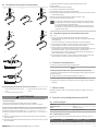
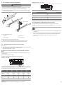
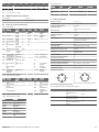
5.3 Schaltpunkte speichern
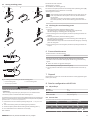
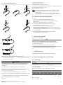
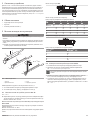
1 s
3 s
7290 7290
AB
C
Abb.2: Schaltpunkte einlernen und kontrollieren
A Einlernen Schaltpunkt 1 B Einlernen Schaltpunkt 2
C Kontrollieren der gespeicherten Posi-
tionen
WARNUNG
Unkontrollierte Bewegungen der Aktoren beim Einschalten der Pneumatik!
Es besteht Verletzungsgefahr, wenn sich das System in einem undefinierten
Zustand befindet.
uBringen Sie das System in einen definierten Zustand, bevor Sie es einschal-
ten!
Die Inbetriebnahme darf nur von einer Elektro- oder Pneumatikfachkraft oder
von einer unterwiesenen Person unter Leitung und Aufsicht einer Fachkraft
durchgeführt werden. Siehe g2.3Qualifikation des Personals.
1. Legen Sie am Sensor eine geeignete Betriebsspannung an. Siehe g9.Techni-
sche Daten.
2. Lernen Sie den Arbeitshub (zwei Schaltpunkte) wie folgt ein (Teach in):
3. Legen Sie die erste Kolbenposition für Arbeitshub (1. Schaltpunkt) fest.
4. Drücken Sie den Teach-Taster 3s lang (A).
LED1 blinkt.
uTeach-Taster loslassen.
1. Schaltpunkt ist gespeichert,
LED2 blinkt (für 2. Schaltpunkt).
uLegen Sie die zweite Kolbenposition für den Arbeitshub (2. Schaltpunkt) fest
(B)
Drücken Sie den Teach-Taster 1s lang (B).
Der 2.Schaltpunkt ist gespeichert.
Wenn sich der Schaltpunkt außerhalb des Detektionsbereichs des Sen-
sors befindet, wird der Einlernvorgang abgebrochen. In diesem Fall
blinkt die LED in kurzen Intervallen.
Wenn der Einlernvorgang nicht abgeschlossen wird, wird dieser nach
90s (Timeout) abgebrochen. Die zuletzt gespeicherten Schaltpunkte
bleiben aktiv.
5.4 Gespeicherte Schaltpunkte kontrollieren
Siehe gAbb.2
1. Bewegen Sie den Kolben in Stellung des ersten Schaltpunkts.
LED des ersten Schaltpunkts leuchtet: Schaltpunkt wurde erkannt (C).
LED leuchtet nicht: Schaltpunkt wurde nicht erkannt.
2. Wurde der Schaltpunkt nicht erkannt, überprüfen Sie die Einsatzbedingungen
und justieren Sie neu.
3. Bewegen Sie den Kolben in Stellung des zweiten Schaltpunkts.
LED des ersten Schaltpunkts erlischt, die des zweiten Schaltpunkts leuchtet:
Schaltpunkt wurde erkannt (C).
Erlischt die erste LED nicht bzw. leuchtet die zweite LED nicht: Schaltpunkt
wurde nicht erkannt.
4. Wurde der Schaltpunkt nicht erkannt, überprüfen Sie die Einsatzbedingungen
und justieren Sie neu.
6 Pflege und Wartung
Der Sensor ST4-2P ist wartungsfrei.
ACHTUNG
Beschädigung der Oberfläche durch Lösemittel und aggressive Reinigungs-
mittel!
Die Oberflächen und Dichtungen können durch Lösemittel oder aggressive
Reinigungsmittel beschädigt werden.
uVerwenden Sie niemals Lösemittel oder aggressive Reinigungsmittel.
1. Überprüfen Sie regelmäßig die Verschraubungen und Steckverbindungen.
2. Beachten Sie die Wartungsintervalle und Vorgaben der Gesamtanlage.
7 Entsorgung
Entsorgen Sie den Sensor ST4-2P nach den Bestimmungen Ihres Landes.
8 Daten zur Konfiguration mit I/O-Link
8.1 Physikalische Schicht
SIO-Modus ja
Min. Zykluszeit 2,3 ms
Geschwindigkeit 38,4kBaud (Com2)
Prozessdatenbreite 2Bit (Frametyp2.1)
8.2 Prozessdaten
Die Sensoren mit I/O-Link haben 2-Bit-Prozessdaten in Bit0 und Bit1.
Zugriff Daten Datentyp Default
R 1 Byte UINT8 0
RW RW RW RW RW RW RW RW
Bit7 Bit6 Bit5 Bit4 Bit3 Bit2 Q2
Bit1
Q1
Bit0
AVENTICS™ ST4-2P | R412012414-BAL-001-AF | Deutsch 5

Bit7 ... 2: reserviert
Bit1 ... 0: 0 = inaktiv, 1 = aktiv
8.3 Direkte Parameter-Seite
HerstellerID 001F hex
ProduktID ST4-2P 0021505
8.4 Servicedaten (I/O-Link)
Tab.1: SPDU-Index
Index Meaning Format
Bytes
Access Example Range Remark
0x10 Manufacturer ID Visible
string
R AVENTICS
GmbH
Exactly 16
strings
0x12 Device ID Visible
string
R ST4-2P ST4-2P Exactly 16
strings
0x15 Serial number Visible
string
R 123dez 1-2E32
0x16 HW version num-
ber
Visible
string
R 1.00
0x17 SW version num-
ber
Visible
string/4
Byte
R 2.33
0x18 Application-speci-
fic name
Visible
string/max
. 16 Byte
R/W
0x90 Teach parameter:
switching point 1
UINT8, 8
Byte
R 0…1023 No arguments
0x91 Teach parameter:
switching point 2
UINT8, 8
Byte
R 0…1023 No arguments
0x92 Tolerance step UINT8, 3
Byte
R/W 1-5
0x28 Process data
state:
output 1 and out-
put 2
UINT8, 1
Byte
R 00
01
10
11
Q1, Q2 inactive
Q1 active
Q2 active
Q1, Q2 active
0xE2 Hall signals
channel A and
channel B
UINT8, 4
Byte
R 0…1023 High Byte
Low Byte
Subindex enthält keine Daten.
Tab.2: SPDU System Command
Index Meaning Format
Bytes
Access Example Range Remark
0x02 Teach switching
point 1
UINT8 W AxA0 Teach command
SP1
Teach switching
point 2
0xA1 Teach command
SP2
Lock global key 0xA3 Deactivates te-
ach button
Unlock global key 0xA4 Activates teach
button
Subindex enthält keine Daten.
Tab.3: SPDU-Index error codes
Index Subindex
0x1000 Communication error
0x5200 Buffer overflow
0x5600 Checksum error
0x5800 Illegal SPDU
0x80xx Device-specific error
0x8000 No details
0x8023 Access denied
0x8030 Parameter value out of
range
Tab.4: Event data
Meaning Mode Type Instance Error code
Parameter chan-
ged
Once Info Application 0xFF10
Communication
error
Once Error Unknown 0xFF10
9 Technische Daten
Messbereich 0…50mm
Elektrische Ausführung DC4 (Leiter)
Versorgungsspannung DC 12…30V
Restwelligkeit ≤10%
(Bezogen auf die Betriebsspannung)
Spannungsabfall ≤2,2V
Stromaufnahme (nicht betätigt) ≤15mA
Dauerstrom ≤100mA
Hysterese 1,0mT
Reproduzierbarkeit ≤0,1mT
(Bei konstanter Versorgungsspannung und
Umgebungstemperatur)
EMV EN60 947-5-2
Schaltausgang PNP
Ausgangsfunktion Schließerfunktion
Anschlussart: Leitung
Leitung mit Stecker (4-polig)
2m PUR, 0,3m PUR
M8, M12
Schnittstelle mit/ohne I/O-Link
(je nach Ausführung)
Schutzart IP67
Drahtbruchschutz ja
Kurzschlussfestigkeit ja
Verpolungsschutz ja
Einschaltimpulsunterdrückung ja
Schock-/Schwingbeanspruchung 30g, 11ms/10…55Hz, 1mm
Gehäusewerkstoff PA
Umgebungstemperatur –20…+75°C
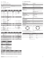
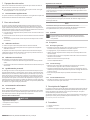
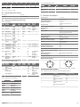
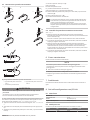
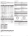
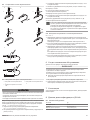
Pinbelegung
1 BN
4 BK
3 BU
2 WH
Abb.3: Stecker M12x1, 4-polig
2 WH
1 BN
4 BK
3 BU
Abb.4: Stecker M8x1, 4-polig
Tab.5: Pinbelegung für Stecker M8x1 und M12x1
PIN Verwendung Kabel/Aderfarbe
1 +UB:
24-V-Versorgung
Braun
2 Out 1:
Schaltausgang 1
Weiß
3 GND:
Bezugspotential
Blau
4 Out 2:
Schaltausgang 2/IO-Link
Schwarz
AVENTICS™ ST4-2P | R412012414-BAL-001-AF | Deutsch 6


AVENTICS™ ST4-2P | R412012414-BAL-001-AF | English 8
Contents
1 About this document......................................................................................................................................................................................................... 9
1.1 Related documents........................................................................................................................................................................................................... 9
2 For your safety................................................................................................................................................................................................................... 9
2.1 Intended use..................................................................................................................................................................................................................... 9
2.2 Improper use .................................................................................................................................................................................................................... 9
2.3 Personnel qualifications .................................................................................................................................................................................................... 9
2.4 Presentation of information .............................................................................................................................................................................................. 9
2.4.1 Warnings............................................................................................................................................................................................................ 9
2.4.2 Symbols ............................................................................................................................................................................................................. 9
2.5 The following must be observed: ...................................................................................................................................................................................... 9
2.5.1 General information........................................................................................................................................................................................... 9
2.5.2 During assembly: ............................................................................................................................................................................................... 9
2.5.3 During operation:............................................................................................................................................................................................... 9
3 Device description............................................................................................................................................................................................................. 9
4 Scope of delivery ............................................................................................................................................................................................................... 9
5 Assembly and commissioning............................................................................................................................................................................................ 9
5.1 Mechanically adjusting the ST4-2P sensor......................................................................................................................................................................... 10
5.2 Electronically adjusting the ST4-2P sensor ........................................................................................................................................................................ 10
5.3 Storing switching points ................................................................................................................................................................................................... 11
5.4 Checking the stored switching points ............................................................................................................................................................................... 11
6 Care and maintenance....................................................................................................................................................................................................... 11
7 Disposal............................................................................................................................................................................................................................. 11
8 Data for configuration with IO-Link.................................................................................................................................................................................... 11
8.1 Physical layer..................................................................................................................................................................................................................... 11
8.2 Process data...................................................................................................................................................................................................................... 11
8.3 Direct parameter page...................................................................................................................................................................................................... 12
8.4 Service data (IO-Link) ........................................................................................................................................................................................................ 12
9 Key technical data ............................................................................................................................................................................................................. 12

1 About this document
These instructions contain important information on the safe and appropriate in-
stallation and operation of the ST4-2P sensor.
uRead these instructions completely before working with the ST4-2P sensor.
Also see in particular g2.For your safety.
1.1 Related documents
The ST4-2P sensor is a system component. Also observe the system documenta-
tion from the system manufacturer.
2 For your safety
The ST4-2P sensor has been manufactured according to the accepted rules of
safety and current technology. There is, however, still a danger of personal injury
or damage to equipment if the following general safety instructions and the
warnings before the steps contained in these instructions are not complied with.
1. Read these instructions completely before working with the ST4-2P sensor.
2. Keep these instructions in a location where they are accessible to all users at
all times.
3. Always include the operating instructions when you pass the ST4-2P sensor on
to third parties.
2.1 Intended use
1. The ST4-2P sensor is for commercial use only.
2. Only use the ST4-2P sensor in AVENTICS handling devices with C-slot.
3. Use within the limits listed in the technical data.
Intended use includes having read and understood these instructions, especially
the chapter g2.For your safety.
2.2 Improper use
It is considered improper use when the ST4-2P sensor
• is used for any application not stated in these instructions, or
• is used under operating conditions that deviate from those described in these
instructions.
2.3 Personnel qualifications
Assembly and commissioning require basic electrical and pneumatic knowledge.
Assembly and commissioning may therefore only be carried out by qualified elec-
trical or pneumatic personnel or an instructed person under the direction and su-
pervision of qualified personnel. Qualified personnel are those who can recognize
possible dangers and institute the appropriate safety measures, due to their pro-
fessional training, knowledge, and experience, as well as their understanding of
the relevant regulations pertaining to the work to be done. Qualified personnel
must observe the rules relevant to the subject area.
2.4 Presentation of information
2.4.1 Warnings
In this documentation, there are warning notes before the steps whenever there
is a risk of personal injury or damage to equipment. The measures described to
avoid these hazards must be followed.
Structure of warnings
SIGNAL WORD
Hazard type and source
Consequences of non-observance
uPrecautions
Meaning of the signal words
WARNING
Possible danger to the life and health of persons.
Failure to observe these notices can result in serious health consequences, in-
cluding death.
CAUTION
Possible dangerous situation.
Failure to observe these notices may result in minor injuries or damage to
property.
NOTICE
Possibility of damage to property or malfunction.
Failure to observe these notices may result in damage to property or malfunc-
tions, but not in personal injury.
2.4.2 Symbols
Recommendation for the optimum use of our products.
Observe this information to ensure the smoothest possible operation.
2.5 The following must be observed:
2.5.1 General information
• Observe the regulations for accident prevention and environmental protec-
tion for the country where the device is used and at the workplace.
• Do not modify or convert the device.
• Only use the device within the performance range provided in the technical
data.
• The ST4-2P sensor is not a safety component in terms of the Machinery Direc-
tive.
• Use a power source in compliance with
IEC/DINEN60204-1.
2.5.2 During assembly:
• Make sure the relevant system component is without pressure or voltage be-
fore assembling the product or when connecting and disconnecting plugs.
• Protect the system against being restarted. Hang signs on the main switches
that warn workers against switching the system on.
• Avoid ferritic parts in the immediate vicinity of the sensor
ST4-2P.
2.5.3 During operation:
• Only commission the sensor after it has been completely assembled, aswell
as correctly connected and tested.
3 Device description
The ST4-2P sensor is a magnetic position sensor with two switching points. It is
intended for end position inquiry and intermediate position detection on pneu-
matic cylinders. The ST4-2P sensor detects positions without any contact.
Using the teach-in button, switching points can be set exactly for all piston posi-
tions. See g5.3Storing switching points.
4 Scope of delivery
• 1 set of operating instructions
• 1x sensor
• 1x hexagon screwdriver wrench size 1.3
5 Assembly and commissioning
WARNING
Danger of injury if assembled under pressure!
Injuries and damage to the device or system components may occur if the
pressure is not switched off before beginning assembly.
uMake sure that the relevant system part is without pressure before you as-
semble theproduct.
AVENTICS™ ST4-2P | R412012414-BAL-001-AF | English 9

MA = 8+5
Ncm
1
2
3
4
Fig.1: Mounting the sensor
1 Sensor 2 C-slot
3 Mounting screw 4 Center of sensor
Required tool: Hexagon screwdriver wrench size SW1.3.
1. Set your handling device to the center of the working stroke.
2. Insert the sensor (1) from above in the center of the C-slot (2).
5.1 Mechanically adjusting the ST4-2P sensor
See gFig.1
uAlign the sensor to the center of the measurement range (observing the cen-
ter of the sensor (4)) and tighten the mounting screw (3).
Tightening torque: MA=8+5Ncm.
Mechanically adjusting the ST4-2P sensor for cylinders, MSC and RCM
series
Align the center of the sensor to the center of the stroke(X) of the actuators and
firmly tighten the mounting screw.
Tightening torque: MA=8+5Ncm.
Also observe the following during assembly:
MSC series mini slides
X
The mini slides must be retracted.
The stroke center (X) is measured from the front plate.
Stroke 10
mm
20
mm
30
mm
40
mm
50
mm
MSC
variants
Stroke center
(X)
Stroke center
(X)
Stroke center
(X)
Stroke center
(X)
Stroke center
(X)
844 39 44 49 54
12 65 60 55 60 65
16 63 58 53 58 64
20 69 64 59 65 68
25 80 75 70 75 82
Series RCM rotary compact module
X
The stroke center (X) is measured from the end cover.
RCM variants Stroke center (X) in mm
635.5
838.5
12 54
16 58
20 62
25 82.5
5.2 Electronically adjusting the ST4-2P sensor
1. Set your handling device to the center of the working stroke.
2. Connect the sensor to a suitable operating voltage. See g9.Key technical
data.
The sensor must be switched on outside of any magnetic fields that
could influence it.
3. Press the teach-in button 8-10s until both LEDs flash alternately.
4. Insert the sensor (1) from above in the C-slot (2), slide the sensor in the C-slot
until both LEDs are on simultaneously, and tighten the mounting screw (3).
Tightening torque: MA=8+5Ncm. See gFig.1.
AVENTICS™ ST4-2P | R412012414-BAL-001-AF | English 10

5.3 Storing switching points
1 s
3 s
7290 7290
AB
C
Fig.2: Teaching in and checking the stored switching points
A Teach switching point 1 B Teach switching point 2
C Check taught-in positions
WARNING
Risk of uncontrolled actuator movements when the pneumatics are
switched on!
There is a danger of personal injury if the system is in an undefined state.
uPut the system in a defined state before switching it on.
Commissioning may only be carried out by qualified electrical or pneumatic per-
sonnel or an instructed person under the direction and supervision of qualified
personnel. See g2.3Personnel qualifications.
1. Connect the sensor to a suitable operating voltage. See g9.Key technical
data.
2. Teach in the working stroke (two switching points) as follows:
3. Set the first piston position for the working stroke (switching point 1).
4. Press and hold the teach-in button for 3seconds (A).
LED1 will flash.
uRelease the teach-in button.
Switching point 1 is stored.
LED 2 will flash (for switching point 2).
uSet the second piston position for the working stroke (switching point 2) (B).
Press and hold the teach-in button for 1second (B).
Switching point 2 is stored.
If the switching point is outside the detection range of the sensor, the
teach-in process will be interrupted. In this case, the LED will flash in
short intervals.
If the teach-in process is not complete, it will be interrupted after
90seconds (timeout). The last stored switching points will remain ac-
tive.
5.4 Checking the stored switching points
See gFig.2
1. Move the piston to the position of switching point 1.
The switching point 1 LED lights up: switching point recognized (C).
LED does not light up: switching point not recognized.
2. If the switching point is not recognized, check the operating conditions and
readjust.
3. Move the piston to the position of switching point 2.
The switching point 1 LED goes out and the switching point 2 LED lights up:
switching point recognized (C).
If the first LED does not go out or the second LED does not light up: switching
point not recognized.
4. If the switching point is not recognized, check the operating conditions and
readjust.
6 Care and maintenance
The ST4-2P sensor is maintenance-free.
NOTICE
Damage to the surface caused by solvents and aggressive detergents!
The surfaces and seals could be damaged by solvents or aggressive cleaning
agents.
uNever use solvents or aggressive detergents.
1. Check the fittings and plug connections regularly.
2. Comply with the maintenance intervals and specifications for the entire sys-
tem.
7 Disposal
Dispose of the ST4-2P sensor in accordance with the currently applicable regula-
tions in your country.
8 Data for configuration with IO-Link
8.1 Physical layer
SIO mode Yes
Min. cycle time 2.3ms
Speed 38.4kBaud (Com2)
Process data width 2bits (frame type2.1)
8.2 Process data
The sensors with IO-Link have 2-bit process data in bit0 and bit1.
Access Data Data type Default
R 1 byte UINT8 0
RW RW RW RW RW RW RW RW
Bit7 Bit6 Bit5 Bit4 Bit3 Bit2 Q2
Bit1
Q1
Bit0
AVENTICS™ ST4-2P | R412012414-BAL-001-AF | English 11

Bit7 ... 2: reserved
Bit1 ... 0: 0 = inactive, 1 = active
8.3 Direct parameter page
ManufacturerID 001F hex
ProductID ST4-2P 0021505
8.4 Service data (IO-Link)
Table1: SPDU index
Index Meaning Format
Bytes
Access Example Range Remark
0x10 Manufacturer ID Visible
string
R AVENTICS
GmbH
Exactly 16
strings
0x12 Device ID Visible
string
R ST4-2P ST4-2P Exactly 16
strings
0x15 Serial number Visible
string
R 123dez 1-2E32
0x16 HW version num-
ber
Visible
string
R 1.00
0x17 SW version num-
ber
Visible
string/4
Byte
R 2.33
0x18 Application-spe-
cific name
Visible
string/max
. 16 Byte
R/W
0x90 Teach parameter:
switching point 1
UINT8, 8
Byte
R 0…1023 No arguments
0x91 Teach parameter:
switching point 2
UINT8, 8
Byte
R 0…1023 No arguments
0x92 Tolerance step UINT8, 3
Byte
R/W 1-5
0x28 Process data
state:
output 1 and out-
put 2
UINT8, 1
Byte
R 00
01
10
11
Q1, Q2 inactive
Q1 active
Q2 active
Q1, Q2 active
0xE2 Hall signals
channel A and
channel B
UINT8, 4
Byte
R 0…1023 High Byte
Low Byte
Subindex contains no data.
Table2: SPDU system command
Index Meaning Format
Bytes
Access Example Range Remark
0x02 Teach switching
point 1
UINT8 W AxA0 Teach command
SP1
Teach switching
point 2
0xA1 Teach command
SP2
Lock global key 0xA3 Deactivates
teach button
Unlock global key 0xA4 Activates teach
button
Subindex contains no data.
Table3: SPDU index error codes
Index Subindex
0x1000 Communication error
0x5200 Buffer overflow
0x5600 Checksum error
0x5800 Illegal SPDU
0x80xx Device-specific error
0x8000 No details
0x8023 Access denied
0x8030 Parameter value out of
range
Table4: Event data
Meaning Mode Type Instance Error code
Parameter
changed
Once Info Application 0xFF10
Communication
error
Once Error Unknown 0xFF10
9 Key technical data
Measuring range 0…50mm
Electrical version DC4 (wire)
Supply voltage DC 12…30V
Residual ripple ≤10%
(Based on the operating voltage)
Voltage drop ≤2.2V
Power consumption (not actuated) ≤15mA
Continuous current ≤100mA
Hysteresis 1.0mT
Reproducibility ≤0.1mT
(At a constant power supply and ambient
temperature)
EMC EN60 947-5-2
Switch output PNP
Output function Make contact function
Connection type: cable
Cable with plug (4-pin)
2m PUR, 0.3m PUR
M8, M12
Interface with/without IO-Link
(depending on version)
Degree of protection IP67
Wire break protection Yes
Short circuit resistance Yes
Reverse polarity protection Yes
Switch-on pulse suppression Yes
Shock/vibration load 30g, 11ms/10…55Hz, 1mm
Housing material PA
Ambient temperature –20…+75°C
Pin assignment
1 BN
4 BK
3 BU
2 WH
Fig.3: Plug, M12x1, 4-pin
2 WH
1 BN
4 BK
3 BU
Fig.4: Plug, M8x1, 4-pin
Table5: Pin assignment for plugs M8x1 and M12x1
Pin Use Cable/wire color
1 +UB:
24 V supply
Brown
2 Out 1:
Switch output 1
White
3 GND:
Reference potential
Blue
4 Out 2:
Switch output 2/IO-Link
Black
AVENTICS™ ST4-2P | R412012414-BAL-001-AF | English 12


AVENTICS™ ST4-2P | R412012414-BAL-001-AF | Français 14
Sommaire
1 À propos de cette notice .................................................................................................................................................................................................... 15
1.1 Documentation supplémentaire....................................................................................................................................................................................... 15
2 Pour votre sécurité ............................................................................................................................................................................................................ 15
2.1 Utilisation conforme ......................................................................................................................................................................................................... 15
2.2 Utilisation non conforme .................................................................................................................................................................................................. 15
2.3 Qualification du personnel ................................................................................................................................................................................................ 15
2.4 Présentation des informations .......................................................................................................................................................................................... 15
2.4.1 Mises en garde ................................................................................................................................................................................................... 15
2.4.2 Symboles ........................................................................................................................................................................................................... 15
2.5 À respecter........................................................................................................................................................................................................................ 15
2.5.1 Remarques générales: ....................................................................................................................................................................................... 15
2.5.2 Lors du montage: .............................................................................................................................................................................................. 15
2.5.3 Lors du fonctionnement: ................................................................................................................................................................................... 15
3 Description de l’appareil.................................................................................................................................................................................................... 15
4 Fourniture ......................................................................................................................................................................................................................... 15
5 Montage et mise en service ............................................................................................................................................................................................... 16
5.1 Ajustage mécanique du capteur ST4-2P............................................................................................................................................................................ 16
5.2 Ajustage électronique du capteur ST4-2P.......................................................................................................................................................................... 16
5.3 Enregistrement des points de commutation ..................................................................................................................................................................... 17
5.4 Contrôle des points de commutation mémorisés.............................................................................................................................................................. 17
6 Entretien et maintenance .................................................................................................................................................................................................. 17
7 Mise au rebut..................................................................................................................................................................................................................... 17
8 Données sur la configuration avec lien E/S ......................................................................................................................................................................... 17
8.1 Couche physique .............................................................................................................................................................................................................. 17
8.2 Données de processus ...................................................................................................................................................................................................... 17
8.3 Page de paramètres directe .............................................................................................................................................................................................. 18
8.4 Données de maintenance (lien E/S)................................................................................................................................................................................... 18
9 Données techniques .......................................................................................................................................................................................................... 18

1 À propos de cette notice
Cette notice contient des informations importantes pour installer et utiliser le
capteur ST4-2P de manière sûre et conforme.
uLire la présente notice avant de travailler avec le capteur ST4-2P. Voir égale-
ment en particulier g2.Pour votre sécurité.
1.1 Documentation supplémentaire
Le capteur ST4-2P est un composant d’installation. Tenir également compte de la
documentation d’installation du fabricant de l’installation.
2 Pour votre sécurité
Le capteur ST4-2P a été fabriqué conformément aux techniques les plus mo-
dernes et aux règles de sécurité technique reconnues. Néanmoins, il existe un
risque de blessures corporelles et de dommages matériels si les consignes de sé-
curité générales suivantes ainsi que les avertissements précédant les instructions
contenus dans la présente notice ne sont pas respectés.
1. Lire entièrement et soigneusement la présente notice avant de travailler avec
le capteur ST4-2P.
2. Conserver cette notice de sorte qu’elle soit accessible à tout instant à tous les
utilisateurs.
3. Transmettre le capteur ST4-2P à de tierces personnes toujours avec la notice
d’instruction.
2.1 Utilisation conforme
1. Utiliser le capteur ST4-2P uniquement dans le domaine industriel.
2. Utiliser le capteur ST4-2P uniquement avec les appareils de manipulation
AVENTICS à rainure C.
3. Respecter les limites de puissance indiquées dans les données techniques.
L’utilisation conforme inclut le fait d’avoir lu et compris la présente notice et en
particulier le chapitre g2.Pour votre sécurité.
2.2 Utilisation non conforme
Une utilisation non conforme du capteur ST4-2P correspond à:
• Une utilisation en dehors des domaines d’application cités dans la présente
notice.
• Une utilisation déviant des conditions de fonctionnement décrites dans la pré-
sente notice.
2.3 Qualification du personnel
Le montage et la mise en service exigent des connaissances électriques et pneu-
matiques fondamentales. Le montage et la mise en service ne doivent donc être
effectués que par un technicien en électronique ou pneumatique ou par une per-
sonne instruite et sous la direction et la surveillance d’un technicien. Un techni-
cien est une personne qui, en raison de sa formation, de ses connaissances et de
son expérience ainsi que de sa connaissance des dispositions en vigueur, est ca-
pable d’évaluer les travaux qui lui sont confiés, de détecter les risques potentiels
et de prendre les mesures de sécurité qui s’imposent. Une personne qualifiée doit
se conformer aux règles techniques pertinentes.
2.4 Présentation des informations
2.4.1 Mises en garde
Dans la présente documentation, des avertissements précèdent les instructions
dont l’exécution recèle un risque de dommages corporels ou matériels. Les me-
sures décrites pour éviter les dangers doivent être respectées.
Structure des avertissements
MOT-CLE
Type et source de risque
Conséquences du non-respect
uPrécautions
Signification des mots-clés
AVERTISSEMENT
Danger potentiellement imminent menaçant la vie et la santé de personnes.
Le non-respect de ces consignes peut entraîner de lourdes répercussions sur la
santé, voire la mort.
ATTENTION
Situation potentiellement dangereuse.
Le non-respect de ces consignes peut entraîner des blessures légères ou des
dommages matériels.
AVIS
Possibilité de dommages matériels ou de dysfonctionnements.
Le non-respect de ces consignes peut entraîner des dommages matériels ou
des dysfonctionnements, mais pas de dommages corporels.
2.4.2 Symboles
Recommandation pour une utilisation optimale de nos produits.
Respecter ces informations afin de garantir le meilleur fonctionne-
ment possible.
2.5 À respecter
2.5.1 Remarques générales:
• Respecter les consignes de prévention d’accidents et de protection de l’envi-
ronnement dans le pays d’utilisation et au poste de travail.
• En règle générale, ne pas modifier ni transformer l’appareil.
• Utiliser l’appareil uniquement dans le champ de travail indiqué dans les don-
nées techniques.
• Le capteur ST4-2P n’est pas un composant de sécurité au sens où l’entend la
directive sur les machines.
• Utiliser une source de courant prescrite par
la norme CEI/DINEN60204-1.
2.5.2 Lors du montage:
• Mettre la partie concernée de l’installation hors tension et hors pression,
avant de monter l’appareil ou de le brancher ou débrancher.
• Protéger l’installation de toute remise en marche. Lors du montage, les com-
mutateurs principaux doivent être dotés de panneaux de danger interdisant la
remise en marche.
• Éviter tout composant ferritique à proximité immédiate du capteur
ST4-2P.
2.5.3 Lors du fonctionnement:
• Ne mettre le capteur en service que lorsqu’il est complètement monté, cor-
rectement raccordé et après l’avoir testé.
3 Description de l’appareil
Le capteur ST4-2P est un capteur de position magnétique doté de deux points de
commutation. Il est destiné à l’interrogation de la position finale ainsi qu’à la dé-
tection de positions intermédiaires sur les vérins pneumatiques. Le capteur
ST4-2P détecte les positions sans contact.
À l’aide de la touche d’apprentissage, les points de commutation peuvent être ré-
glés de façon exacte pour les positions de piston souhaitées. Voir g5.3Enregis-
trement des points de commutation.
4 Fourniture
• 1x notice d’instruction
• 1x capteur
• 1x tournevis hexagonal à six pans, ouverture de clé1,3
AVENTICS™ ST4-2P | R412012414-BAL-001-AF | Français 15

5 Montage et mise en service
AVERTISSEMENT
Risque de blessure dû à un montage sous pression!
Si la pression n’est pas coupée avant d’entamer le montage, il existe un risque
de blessures et d’endommagement de l’appareil ou de certaines parties de
l’installation.
uMettre toutes les parties pertinentes de l’installation hors pression avant de
monter le produit.
MA = 8+5
Ncm
1
2
3
4
Fig.1: Montage du capteur
1 Capteur 2 Rainure C
3 Vis de fixation 4 Milieu du capteur
Outil nécessaire: tournevis pour vis à tête hexagonale, ouverture de clé 1,3.
1. Placer l’appareil de manipulation au centre de la course de service.
2. Insérer le capteur (1) par le haut, au centre de la rainure C (2).
5.1 Ajustage mécanique du capteur ST4-2P
Voir gFig.1
uAligner le capteur avec le milieu de la plage de mesure (respecter le milieu du
capteur (4)) et serrer la vis de fixation (3) à fond.
Couple de serrage: MA=8+5Ncm.
Ajustage mécanique du capteur ST4-2P pour les vérins, série MSC et
RCM
Ajuster le milieu du capteur au centre de course (X) des actionneurs et serrer à
fond la vis de fixation.
Couple de serrage: MA=8+5Ncm.
Lors du montage, respecter les consignes suivantes:
Mini-chariot, série MSC
X
Le mini-chariot doit être rentré.
Le centre de course (X) est mesuré à partir de la plaque frontale.
Course 10
mm
20
mm
30
mm
40
mm
50
mm
Variantes
MSC
Centre de
course (X)
Centre de
course (X)
Centre de
course (X)
Centre de
course (X)
Centre de
course (X)
844 39 44 49 54
12 65 60 55 60 65
16 63 58 53 58 64
20 69 64 59 65 68
Course 10
mm
20
mm
30
mm
40
mm
50
mm
25 80 75 70 75 82
Module rotatif, série RCM
X
Le centre de course (X) est mesuré à partir du couvercle d’extrémité.
Variantes RCM Centre de course (X) en mm
635,5
838,5
12 54
16 58
20 62
25 82,5
5.2 Ajustage électronique du capteur ST4-2P
1. Placer l’appareil de manipulation au centre de la course de service.
2. Établir une tension de service appropriée au capteur. Voir g9.Données tech-
niques.
Le capteur doit être enclenché en dehors de champs magnétiques
pouvant altérer son fonctionnement.
3. Appuyer sur la touche d’apprentissage pendant 8à10s jusqu’à ce que les
deux LED clignotent en alternance.
4. Insérer le capteur (1) dans la rainure C (2) par le haut puis le faire coulisser
dans la rainure C jusqu’à ce que les deux LED s’allument simultanément. Enfin
serrer la vis de fixation (3) à fond. Couple de serrage: MA=8+5Ncm. Voir
gFig.1.
AVENTICS™ ST4-2P | R412012414-BAL-001-AF | Français 16

5.3 Enregistrement des points de commutation
1 s
3 s
7290 7290
AB
C
Fig.2: Apprentissage et contrôle des points de commutation
A Apprentissage du point de commuta-
tion1
B Apprentissage du point de commuta-
tion2
C Contrôler les positions mémorisées
AVERTISSEMENT
Mouvements incontrôlés des actionneurs lors de la mise en marche de la
partie pneumatique!
Il existe un risque de blessure si l’îlot est dans un état indéfini.
uMettre le système dans un état défini avant de le mettre en marche!
La mise en service ne doit être effectuée que par un personnel spécialisé en élec-
tronique ou pneumatique ou par une personne instruite et sous la direction et
surveillance d’une personne qualifiée. Voir g2.3Qualification du personnel.
1. Établir une tension de service appropriée au capteur. Voir g9.Données tech-
niques.
2. Effectuer l’apprentissage de la course de service (deux points de commuta-
tion) comme suit:
3. Déterminer la première position du piston pour la course de service (1er point
de commutation).
4. Maintenir la touche d’apprentissage enfoncée pendant 3s (A).
La LED1 clignote.
uRelâcher la touche d’apprentissage.
Le 1er point de commutation est mémorisé,
la LED2 clignote (pour le 2e point de commutation).
uDéterminer la deuxième position du piston pour la course de service (2e point
de commutation) (B)
Maintenir la touche d’apprentissage enfoncée pendant 1s (B).
Le 2e point de commutation est mémorisé.
Si le point de commutation se trouve en dehors de la plage de détec-
tion du capteur, la procédure d’apprentissage est interrompue. Dans
ce cas, la LED clignote à intervalles courts.
Si la procédure d’apprentissage n’est pas achevée dans les 90s (tem-
porisation), elle s’interrompt. Les derniers points de commutation en-
registrés restent actifs.
5.4 Contrôle des points de commutation mémorisés
Voir gFig.2
1. Placer le piston sur la position du premier point de commutation.
La LED du premier point de commutation s’allume: le point de commutation
a été détecté (C).
La LED ne s’allume pas: le point de commutation n’a pas été détecté.
2. Si le point de commutation n’a pas été détecté, vérifier à nouveau les condi-
tions d’utilisation et ajuster à nouveau le point de commutation.
3. Placer le piston sur la position du deuxième point de commutation.
La LED du premier point de commutation s’éteint, celle du deuxième point de
commutation s’allume: le point de commutation a été détecté (C).
Si la première LED ne s’éteint pas ou si la deuxième LED ne s’allume pas: le
point de commutation n’a pas été détecté.
4. Si le point de commutation n’a pas été détecté, vérifier à nouveau les condi-
tions d’utilisation et ajuster à nouveau le point de commutation.
6 Entretien et maintenance
Le capteur ST4-2P ne nécessite aucune maintenance.
AVIS
Dommages superficiels dus à des solvants et des détergents agressifs!
Les surfaces et les joints peuvent être endommagés par des solvants ou des dé-
tergents agressifs.
uNe jamais utiliser de solvants ou de détergents agressifs.
1. Vérifier régulièrement les vissages et les raccords enfichables.
2. Respecter les intervalles de maintenance et les prescriptions de l’installation
complète.
7 Mise au rebut
Éliminer le capteur ST4-2P en respectant les directives en vigueur dans le pays
d’utilisation.
8 Données sur la configuration avec lien E/S
8.1 Couche physique
Mode SIO Oui
Durée min.du cycle 2,3ms
Vitesse 38,4kBaud (Com2)
Largeur des données des opérations 2bits (type de cadre 2.1)
8.2 Données de processus
Les capteurs avec lien E/S ont des données des opérations de 2bits en bit0 et
bit1.
Accès Données Type de données Par défaut
R 1octet UINT8 0
AVENTICS™ ST4-2P | R412012414-BAL-001-AF | Français 17

RW RW RW RW RW RW RW RW
Bit7 Bit6 Bit5 Bit4 Bit3 Bit2 Q2
Bit1
Q1
Bit0
Bit7 ... 2: réservé
Bit1 ... 0: 0=inactif, 1=actif
8.3 Page de paramètres directe
ID fabricant 001F hex
ID produit ST4-2P 0021505
8.4 Données de maintenance (lien E/S)
Tab.1: Index SPDU
Index Meaning Format
Bytes
Access Example Range Remark
0x10 Manufacturer ID Visible
string
R AVENTICS
GmbH
Exactly 16
strings
0x12 Device ID Visible
string
R ST4-2P ST4-2P Exactly 16
strings
0x15 Serial number Visible
string
R 123dez 1-2E32
0x16 HW version num-
ber
Visible
string
R 1.00
0x17 SW version num-
ber
Visible
string/4
Byte
R 2.33
0x18 Application-speci-
fic name
Visible
string/max
. 16 Byte
R/W
0x90 Teach parameter:
switching point 1
UINT8, 8
Byte
R 0…1023 No arguments
0x91 Teach parameter:
switching point 2
UINT8, 8
Byte
R 0…1023 No arguments
0x92 Tolerance step UINT8, 3
Byte
R/W 1-5
0x28 Process data
state:
output 1 and out-
put 2
UINT8, 1
Byte
R 00
01
10
11
Q1, Q2 inactive
Q1 active
Q2 active
Q1, Q2 active
0xE2 Hall signals
channel A and
channel B
UINT8, 4
Byte
R 0…1023 High Byte
Low Byte
Le sous-index ne contient aucune donnée.
Tab.2: Commande système SPDU
Index Meaning Format
Bytes
Access Example Range Remark
0x02 Teach switching
point 1
UINT8 W AxA0 Teach command
SP1
Teach switching
point 2
0xA1 Teach command
SP2
Lock global key 0xA3 Deactivates
teach button
Unlock global key 0xA4 Activates teach
button
Le sous-index ne contient aucune donnée.
Tab.3: Codes d'erreur index SPDU
Index Subindex
0x1000 Communication error
0x5200 Buffer overflow
0x5600 Checksum error
0x5800 Illegal SPDU
0x80xx Device-specific error
0x8000 No details
0x8023 Access denied
0x8030 Parameter value out of
range
Tab.4: Données d'événement
Meaning Mode Type Instance Error code
Parameter chan-
ged
Once Info Application 0xFF10
Communication
error
Once Error Unknown 0xFF10
9 Données techniques
Plage de mesure 0…50mm
Version électrique CC4 (conducteur)
Tension d’alimentation CC 12…30V
Ondulation résiduelle ≤10%
(Relatif à la tension de service)
Chute de tension ≤2,2V
Puissance absorbée (non activée) ≤15mA
Courant continu ≤100mA
Hystérèse 1,0mT
Reproductibilité ≤0,1mT
(Pour une tension d’alimentation et une tem-
pérature ambiante constantes)
CEM EN60947-5-2
Sortie de commutation PNP
Fonction de sortie Fonction de fermeture
Type de raccordement: câble
Câble avec connecteur (à 4pôles)
2m PUR, 0,3m PUR
M8, M12
Interface Avec/Sans lien E/S
(Selon la version)
Indice de protection IP67
Protection de rupture de fils Oui
Résistance aux courts-circuits Oui
Protection contre les inversions de polarité Oui
Suppression des impulsions d’enclenche-
ment
Oui
Chocs/Charge oscillante 30g, 11ms/10…55Hz, 1mm
Matériau du boîtier PA
Température ambiante –20…+75°C
Affectation des broches
1 BN
4 BK
3 BU
2 WH
Fig.3: Connecteur M12x1, à 4pôles
2 WH
1 BN
4 BK
3 BU
Fig.4: Connecteur M8x1, à 4pôles
Tab.5: Affectation des broches pour connecteurs M8x1 et M12x1
Broche Utilisation Câble/Couleur de fil
1 +UB:
alimentation 24V
Marron
2 Out1:
sortie de commutation1
Blanc
3 GND:
potentiel de référence
Bleu
4 Out2:
sortie de commutation2/lien
E/S
Noir
AVENTICS™ ST4-2P | R412012414-BAL-001-AF | Français 18


AVENTICS™ ST4-2P | R412012414-BAL-001-AF | Italiano 20
Indice
1 Spiegazione delle istruzioni ............................................................................................................................................................................................... 21
1.1 Ulteriore documentazione ................................................................................................................................................................................................ 21
2 Per la vostra sicurezza........................................................................................................................................................................................................ 21
2.1 Utilizzo a norma................................................................................................................................................................................................................ 21
2.2 Utilizzo non a norma ......................................................................................................................................................................................................... 21
2.3 Qualifica del personale...................................................................................................................................................................................................... 21
2.4 Presentazione delle informazioni ...................................................................................................................................................................................... 21
2.4.1 Avvertenze di sicurezza ...................................................................................................................................................................................... 21
2.4.2 Simboli............................................................................................................................................................................................................... 21
2.5 Cosa bisogna osservare..................................................................................................................................................................................................... 21
2.5.1 Indicazioni generali: ........................................................................................................................................................................................... 21
2.5.2 Durante il montaggio:........................................................................................................................................................................................ 21
2.5.3 Durante il funzionamento: ................................................................................................................................................................................. 21
3 Descrizione dell’apparecchio ............................................................................................................................................................................................. 21
4 Fornitura ........................................................................................................................................................................................................................... 21
5 Montaggio e messa in funzione ......................................................................................................................................................................................... 22
5.1 Regolazione meccanica del sensoreST4-2P ...................................................................................................................................................................... 22
5.2 Regolazione elettronica del sensore ST4-2P ...................................................................................................................................................................... 22
5.3 Memorizzare i punti di commutazione.............................................................................................................................................................................. 23
5.4 Controllo dei punti di commutazione memorizzati ........................................................................................................................................................... 23
6 Cura e manutenzione......................................................................................................................................................................................................... 23
7 Smaltimento ..................................................................................................................................................................................................................... 23
8 Dati sulla configurazione con I/O-Link................................................................................................................................................................................ 23
8.1 Strato fisico....................................................................................................................................................................................................................... 23
8.2 Dati di processo ................................................................................................................................................................................................................ 23
8.3 Pagina dei parametri diretti............................................................................................................................................................................................... 24
8.4 Dati per l’assistenza (I/O-Link)........................................................................................................................................................................................... 24
9 Dati tecnici ........................................................................................................................................................................................................................ 24
La pagina si sta caricando...
La pagina si sta caricando...
La pagina si sta caricando...
La pagina si sta caricando...
La pagina si sta caricando...
La pagina si sta caricando...
La pagina si sta caricando...
La pagina si sta caricando...
La pagina si sta caricando...
La pagina si sta caricando...
La pagina si sta caricando...
La pagina si sta caricando...
La pagina si sta caricando...
La pagina si sta caricando...
La pagina si sta caricando...
La pagina si sta caricando...
La pagina si sta caricando...
La pagina si sta caricando...
La pagina si sta caricando...
La pagina si sta caricando...
La pagina si sta caricando...
La pagina si sta caricando...
La pagina si sta caricando...
La pagina si sta caricando...
-
 1
1
-
 2
2
-
 3
3
-
 4
4
-
 5
5
-
 6
6
-
 7
7
-
 8
8
-
 9
9
-
 10
10
-
 11
11
-
 12
12
-
 13
13
-
 14
14
-
 15
15
-
 16
16
-
 17
17
-
 18
18
-
 19
19
-
 20
20
-
 21
21
-
 22
22
-
 23
23
-
 24
24
-
 25
25
-
 26
26
-
 27
27
-
 28
28
-
 29
29
-
 30
30
-
 31
31
-
 32
32
-
 33
33
-
 34
34
-
 35
35
-
 36
36
-
 37
37
-
 38
38
-
 39
39
-
 40
40
-
 41
41
-
 42
42
-
 43
43
-
 44
44


in altre lingue
- français: Emerson ST4-2P Manuel utilisateur
- español: Emerson ST4-2P Manual de usuario
- Deutsch: Emerson ST4-2P Benutzerhandbuch
Documenti correlati
Altri documenti
-
AVENTICS Capteur, série ST4-2P avec et sans I/O Link Manuale del proprietario
-
-
-
-
-
-
-
AVENTICS PM1 Manuale utente