IEI Technology PUZZLE-M801 Manuale utente
- Tipo
- Manuale utente

PUZZLE-M801
Page i
User Manual
MODEL:
PUZZLE-M801
1U Network Appliance with Marvell® ARMADA® 8040 CPU,
DDR4, 32 GB eMMC, 10GbE SFP+ Ports, PCIe x2 Slot, M.2,
Console Port, Dual USB 3.0, Rack Mount, and RoHS
Rev. 1.00 – April 15, 2019

PUZZLE-M801
Page ii
Revision
Date Version Changes
April 15, 2019 1.00 Initial release

PUZZLE-M801
Page iii
Copyright
COPYRIGHT NOTICE
The information in this document is subject to change without prior notice in order to
improve reliability, design and function and does not represent a commitment on the part
of the manufacturer.
In no event will the manufacturer be liable for direct, indirect, special, incidental, or
consequential damages arising out of the use or inability to use the product or
documentation, even if advised of the possibility of such damages.
This document contains proprietary information protected by copyright. All rights are
reserved. No part of this manual may be reproduced by any mechanical, electronic, or
other means in any form without prior written permission of the manufacturer.
TRADEMARKS
All registered trademarks and product names mentioned herein are used for identification
purposes only and may be trademarks and/or registered trademarks of their respective
owners.

PUZZLE-M801
Page iv
Manual Conventions
WARNING
Warnings appear where overlooked details may cause damage to the
equipment or result in personal injury. Warnings should be taken
seriously.
CAUTION
Cautionary messages should be heeded to help reduce the chance of
losing data or damaging the product.
NOTE
These messages inform the reader of essential but non-critical
information. These messages should be read carefully as any directions
or instructions contained therein can help avoid making mistakes.

PUZZLE-M801
Page v
Table of Contents
1 INTRODUCTION .......................................................................................................... 1
1.1 OVERVIEW .................................................................................................................. 2
1.2 MODEL VARIATIONS ................................................................................................... 2
1.3 FEATURES ................................................................................................................... 3
1.4 FRONT PANEL ............................................................................................................. 3
1.5 REAR PANEL ............................................................................................................... 4
1.6 TECHNICAL SPECIFICATIONS ...................................................................................... 4
1.7 DIMENSIONS ............................................................................................................... 6
2 UNPACKING ................................................................................................................. 7
2.1 ANTI-STATIC PRECAUTIONS ........................................................................................ 8
2.2 UNPACKING PRECAUTIONS ......................................................................................... 8
2.3 PACKING LIST ............................................................................................................. 9
2.4 OPTIONAL ITEMS ...................................................................................................... 10
3 INSTALLATION .......................................................................................................... 11
3.1 INSTALLATION PRECAUTIONS ................................................................................... 12
3.2 TOP COVER REMOVAL .............................................................................................. 13
3.3 DIMM INSTALLATION .............................................................................................. 13
3.4 HDD INSTALLATION ................................................................................................. 15
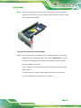
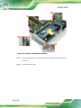
3.5 PCIE EXPANSION CARD INSTALLATION .................................................................... 17
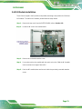
3.6 M.2 MODULE INSTALLATION .................................................................................... 21
3.7 EXTERNAL INTERFACE CONNECTION ....................................................................... 22
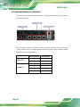
3.7.1 LAN Connection - 1GbE .................................................................................. 23
3.7.2 LAN Connection - 10GbE SFP+ ...................................................................... 25
3.7.3 Console Connection ......................................................................................... 26
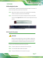
3.8 MOUNTING THE SYSTEM .......................................................................................... 27
3.9 POWER-ON PROCEDURE ........................................................................................... 27
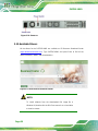
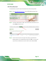
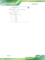
3.10 AVAILABLE DRIVERS .............................................................................................. 28
3.10.1 Driver Download ........................................................................................... 29
4 INTERFACE CONNECTORS ................................................................................... 31

PUZZLE-M801
Page vi
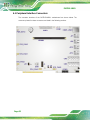
4.1 PERIPHERAL INTERFACE CONNECTORS ..................................................................... 32
4.2 INTERNAL PERIPHERAL CONNECTORS ...................................................................... 33
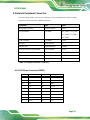
4.2.1 ATX Power Connector (PWR1) ....................................................................... 33
4.2.2 Fan Connectors (CPU_FAN1, SYS_FAN1/2/3/5) ............................................ 34
4.2.3 LCM Connector (COM1) ................................................................................. 34
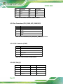
4.2.4 M.2 Slot (J3) ..................................................................................................... 34
4.2.5 PCIe x2 Socket for SATA Module (PCIE2) ...................................................... 36
4.2.6 Power Switch Connector (PWR_BTN1) .......................................................... 37
4.2.7 USB DOM Connector (JP11) ........................................................................... 37
A REGULATORY COMPLIANCE .............................................................................. 38
B SAFETY PRECAUTIONS ......................................................................................... 43
B.1 SAFETY PRECAUTIONS ............................................................................................. 44
B.1.1 General Safety Precautions ............................................................................. 44
B.1.2 Anti-static Precautions .................................................................................... 44
B.1.3 Product Disposal ............................................................................................. 45
B.2 MAINTENANCE AND CLEANING PRECAUTIONS ........................................................ 46
B.2.1 Maintenance and Cleaning .............................................................................. 46
B.2.2 Cleaning Tools ................................................................................................. 46
C HAZARDOUS MATERIALS DISCLOSURE ......................................................... 48

PUZZLE-M801
Page vii
List of Figures
Figure 1-1: PUZZLE-M801 Series .................................................................................................. 2
Figure 1-2: PUZZLE-M801 Front Panel ......................................................................................... 3
Figure 1-3: PUZZLE-M801 Rear Panel .......................................................................................... 4
Figure 1-4: Physical Dimensions (millimeters) ............................................................................ 6
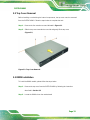
Figure 3-1: Top Cover Removal .................................................................................................. 13
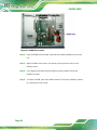
Figure 3-2: DIMM Slot Location ................................................................................................... 14
Figure 3-3: HDD Bracket Retention Screws ............................................................................... 15
Figure 3-4: Secure HDD to the Bracket ...................................................................................... 16
Figure 3-5: HDD Installation ........................................................................................................ 16
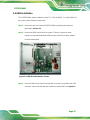
Figure 3-6: Expansion Slot Module Retention Screws ............................................................. 17
Figure 3-7: Disconnect the Expansion Slot Module .................................................................. 18
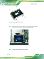
Figure 3-8: Blank Bracket Screw ................................................................................................. 18
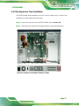
Figure 3-9: PCIe Expansion Card Installation ............................................................................ 19
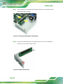
Figure 3-10: Expansion Slot Module Installation ...................................................................... 20
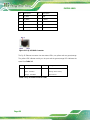
Figure 3-11: RJ-45 1GbE Connector ........................................................................................... 24
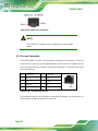
Figure 3-12: 10GbE SFP+ Connector .......................................................................................... 26
Figure 3-13: Rack Mounting Bracket Installation ...................................................................... 27
Figure 3-14: Power-on .................................................................................................................. 28
Figure 3-15: IEI Resource Download Center .............................................................................. 28

PUZZLE-M801
Page viii
List of Tables
Table 1-1: PUZZLE-M801 Model Variations .................................................................................. 2
Table 1-2: Technical Specifications .............................................................................................. 5
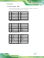
Table 3-1: 1GbE Port1 Pinouts .................................................................................................... 23
Table 3-2: 1GbE Port2 Pinouts .................................................................................................... 23
Table 3-3: 1GbE Port3 Pinouts .................................................................................................... 23
Table 3-4: 1GbE Port4 Pinouts .................................................................................................... 24
Table 3-5: RJ-45 1GbE Connector LEDs .................................................................................... 24
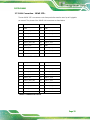
Table 3-6: 10GbE Port1 Pinouts .................................................................................................. 25
Table 3-7: 10GbE Port2 Pinouts .................................................................................................. 25
Table 3-8: RJ-45 Serial Port Pinouts ........................................................................................... 26
Table 4-1: Peripheral Interface Connectors ............................................................................... 33
Table 4-2: ATX Power Connector (PWR1) Pinouts .................................................................... 34
Table 4-3: Fan Connectors (CPU_FAN1, SYS_FAN1/2/3/5) Pinouts ........................................ 34
Table 4-4: LCM Connector (COM1) Pinouts ............................................................................... 34
Table 4-5: M.2 Slot (J3) Pinouts .................................................................................................. 36
Table 4-6: PCIe x2 Socket for SATA Module (PCIE2) Pinouts ................................................. 36
Table 4-7: Power Switch Connector (PWR_BTN1) Pinouts ...................................................... 37
Table 4-8: USB DOM Connector (JP11) Pinouts ........................................................................ 37
PUZZLE-M801

PUZZLE-M801
Page 1
Chapter
1
1 Introduction

PUZZLE-M801
Page 2
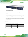
1.1 Overview
Figure 1-1: PUZZLE-M801 Series
The PUZZLE-M801 is a 1U network appliance series powered by Marvell
®
ARMADA
®
8040 processor. It is optimized to host VNFs (Virtual Network Functions) and is ideal for
SD-WAN.
The PUZZLE-M801 supports two 10GbE SFP+ ports and four 1GbE ports for high-speed
network applications, and it is equipped with a PCIe x16 (x2 mode) slot for upgrading with
expansion cards, such as NIC cards or accelerator cards.
Multiple storage interfaces for fast and stable data transmission are offered through two
SATA 6Gb/s connectors.
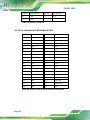
1.2 Model Variations
The model variations of the PUZZLE-M801 are listed below.
Model No. Memory SSD
PUZZLE-M801-A1
N/A N/A
PUZZLE-M801-A1/8G
8 GB DDR4 256 GB
Table 1-1: PUZZLE-M801 Model Variations

PUZZLE-M801
Page 3
1.3 Features
The PUZZLE-M801 features are listed below:
Powered by Marvell
®
ARMADA
®
8040 processor
Support two 2400 MHz DDR4 non-ECC RDIMMs (system max. 16 GB)
32 GB eMMC and support two 2.5” SATA SSD/HDD
Equipped with two 10GbE SFP+ ports
Up to four 1GbE connections via Marvell
®
ALASKA
®
88E1512P PHY
Upgradable with future expansion card by one PCIe x16 (x2 mode) slot and
one M.2 B-key slot
One RJ-45 RS-232 serial port
Supports two USB 3.1 Gen 1 (5 Gb/s) ports
1U chassis for rack mounting
RoHS compliant
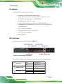
1.4 Front Panel
The overview of the front panel is shown in Figure 1-2.
Figure 1-2: PUZZLE-M801 Front Panel
The states of the system status indicators located on the front panel are listed below.
Power LED
Off The system is off.
Blue The system is on.
HDD Status LED
Off No HDD activity
Blinking Green HDD activity
Alert LED
Off No alert
Red Alert

PUZZLE-M801
Page 4
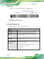
1.5 Rear Panel
An overview of the PUZZLE-M801 rear panel is shown in Figure 1-3 below.
Figure 1-3: PUZZLE-M801 Rear Panel
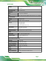
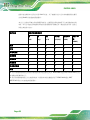
1.6 Technical Specifications
The PUZZLE-M801 technical specifications are listed below.
System
Form Factor 1U
CPU (SoC) Marvell
®
ARMADA
®
8040 processor (quad-core, 1.8 GHz)
Memory
One 288-pin 2400 MHz DDR4 ECC/non-ECC RDIMM slot
(system max. 16 GB)
(8G SKUs are pre-installed with one 8 GB memory module)
Networking 2 x 10GbE SFP+ port
4 x 1GbE LAN port via Marvell
®
ALASKA
®
88E1512P PHY
Network Acceleration
and Security
Configurable packet processor
HW offload for networking
Acceleration engines for storage, networking and security
Public Key Processor (RSA/DH/ECC)
Secure Storage
Secure boot

PUZZLE-M801
Page 5
Storage 2 x 2.5" SATA 6Gb/s HDD/SSD bay
32 GB eMMC
Operating System Linux Ubuntu 16.04
Expansion
PCIe 1 x PCIe x16 (x2 mode) slot
M.2 1 x M.2 B-key 2242 slot (supports SATA and USB 3.1 Gen 1 signals)
I/O and Indicators
Console 1 x RJ-45 RS-232
USB 2 x USB 3.1 Gen 1 (5 Gb/s) port
Indicator Power status (blue)
HDD status (green)
Alert LED (programmable, red)
Switch/Button
Power switch (rear panel)
Reset button (front panel)
Antenna Connector 1 x Knockout hole for antenna connector
Power
Power Input 100 V ~ 240 V ATX power, 250 W
Thermal Solution 1 x Passive heatsink for CPU
4 x Smart fan
Environmental and Mechanical
Mounting 1U rack mount
Operating Temperature 0°C~40°C (32°F~104°F)
Storage Temperature -10°C~50°C (14°F~122°F)
Operating Humidity 5%~90%, non-condensing
Safety CE, FCC
Weight 5 kg
Physical Dimensions 430 mm x 320 mm x 44.2 mm (W x D x H)
Table 1-2: Technical Specifications

PUZZLE-M801
Page 6
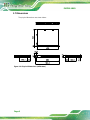
1.7 Dimensions
The physical dimensions are shown below:
Figure 1-4: Physical Dimensions (millimeters)

PUZZLE-M801
Page 7
Chapter
2
2 Unpacking

PUZZLE-M801
Page 8
2.1 Anti-static Precautions
WARNING:
Failure to take ESD precautions during installation
may result in
permanent damage to the PUZZLE-M801 and severe injury to the user.
Electrostatic discharge (ESD) can cause serious damage to electronic components,
including the PUZZLE-M801. Dry climates are especially susceptible to ESD. It is
therefore critical that whenever the PUZZLE-M801 or any other electrical component is
handled, the following anti-static precautions are strictly adhered to.
Wear an anti-static wristband: Wearing a simple anti-static wristband can
help to prevent ESD from damaging the board.
Self-grounding: Before handling the board, touch any grounded conducting
material. During the time the board is handled, frequently touch any
conducting materials that are connected to the ground.
Use an anti-static pad: When configuring the PUZZLE-M801, place it on an
anti-static pad. This reduces the possibility of ESD damaging the
PUZZLE-M801.
2.2 Unpacking Precautions
When the PUZZLE-M801 is unpacked, please do the following:
Follow the anti-static precautions outlined in Section 2.1.
Make sure the packing box is facing upwards so the PUZZLE-M801 does not
fall out of the box.
Make sure all the components shown in Section 2.2 are present.

PUZZLE-M801
Page 9
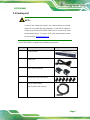
2.3 Packing List
NOTE:
If some of the components listed in the checklist below are missing,
please do not proceed with the installation. Contact the IEI reseller or
vendor you purchased the PUZZLE-M801 from or contact an IEI sales
representative directly. To contact an IEI sales representative, please
send an email to sales@ieiworld.com
.
The PUZZLE-M801 is shipped with the following components:
Quantity Item Image
1 PUZZLE-M801
1 Power cord
2 Rack mounting bracket
6 Mounting bracket screw (M4*6)
1 USB to console cable
(only for SKUs with memory)

PUZZLE-M801
Page 10
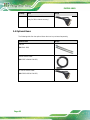
Quantity Item Image
1 RS-232 to console cable
(only for SKUs without memory)
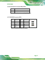
2.4 Optional Items
The following table lists the optional items that can be purchased separately.
Optional Item Image
Slide rail
(P/N: RAIL-B02)
USB to console cable
(P/N: 32013-004000-100-RS)
RS-232 to console cable
(P/N: 32005-005100-100-RS)

PUZZLE-M801
Page 11
Chapter
3
3 Installation

PUZZLE-M801
Page 12
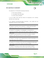
3.1 Installation Precautions
During installation, be aware of the precautions below:
Read the user manual: The user manual provides a complete description of
the PUZZLE-M801, installation instructions and configuration options.
DANGER! Disconnect Power: Power to the PUZZLE-M801 must be
disconnected during the installation process. Failing to disconnect the power
may cause severe injury to the body and/or damage to the system.
Qualified Personnel: The PUZZLE-M801 must be installed and operated
only by trained and qualified personnel. Maintenance, upgrades, or repairs
may only be carried out by qualified personnel who are familiar with the
associated dangers.
Air Circulation: Make sure there is sufficient air circulation when installing
the PUZZLE-M801. The PUZZLE-M801’s cooling vents must not be
obstructed by any objects. Blocking the vents can cause overheating of the
PUZZLE-M801. Leave at least 5 cm of clearance around the PUZZLE-M801
to prevent overheating.
Grounding: The PUZZLE-M801 should be properly grounded. The voltage
feeds must not be overloaded. Adjust the cabling and provide external
overcharge protection per the electrical values indicated on the label attached
to the back of the PUZZLE-M801.
La pagina si sta caricando...
La pagina si sta caricando...
La pagina si sta caricando...
La pagina si sta caricando...
La pagina si sta caricando...
La pagina si sta caricando...
La pagina si sta caricando...
La pagina si sta caricando...
La pagina si sta caricando...
La pagina si sta caricando...
La pagina si sta caricando...
La pagina si sta caricando...
La pagina si sta caricando...
La pagina si sta caricando...
La pagina si sta caricando...
La pagina si sta caricando...
La pagina si sta caricando...
La pagina si sta caricando...
La pagina si sta caricando...
La pagina si sta caricando...
La pagina si sta caricando...
La pagina si sta caricando...
La pagina si sta caricando...
La pagina si sta caricando...
La pagina si sta caricando...
La pagina si sta caricando...
La pagina si sta caricando...
La pagina si sta caricando...
La pagina si sta caricando...
La pagina si sta caricando...
La pagina si sta caricando...
La pagina si sta caricando...
La pagina si sta caricando...
La pagina si sta caricando...
La pagina si sta caricando...
La pagina si sta caricando...
La pagina si sta caricando...
La pagina si sta caricando...
-
 1
1
-
 2
2
-
 3
3
-
 4
4
-
 5
5
-
 6
6
-
 7
7
-
 8
8
-
 9
9
-
 10
10
-
 11
11
-
 12
12
-
 13
13
-
 14
14
-
 15
15
-
 16
16
-
 17
17
-
 18
18
-
 19
19
-
 20
20
-
 21
21
-
 22
22
-
 23
23
-
 24
24
-
 25
25
-
 26
26
-
 27
27
-
 28
28
-
 29
29
-
 30
30
-
 31
31
-
 32
32
-
 33
33
-
 34
34
-
 35
35
-
 36
36
-
 37
37
-
 38
38
-
 39
39
-
 40
40
-
 41
41
-
 42
42
-
 43
43
-
 44
44
-
 45
45
-
 46
46
-
 47
47
-
 48
48
-
 49
49
-
 50
50
-
 51
51
-
 52
52
-
 53
53
-
 54
54
-
 55
55
-
 56
56
-
 57
57
-
 58
58


IEI Technology PUZZLE-M801 Manuale utente
- Tipo
- Manuale utente
in altre lingue
Documenti correlati

Altri documenti
-
QNAP QSW-3216R-8S8T Quick Installation Guide
-
IEI Integration PUZZLE-9030 Manuale utente
-
-
Juniper JSA3500 Manuale utente
-
-
-
Mellanox Technologies MSX1024B-2BFS Manuale utente
-
Avid NEXIS NEXIS Pro 6.0 Guida utente
-
-
Juniper NFX350 Manuale utente