IEI Integration IASO-W07A-N6210 Manuale utente
- Tipo
- Manuale utente

IASO-W07A-N6210 Medical Panel PC
Page i
[MODEL NAME]
User Manual
IASO-W07A-N6210
MODEL:
7" Medical Panel PC with Intel® Celeron® Processor N6210,
P-CAP Touchscreen, 8 GB LPDDR4x, 32GB eMMC, HDMI Output,
Six USB 3.2, Wi-Fi 6, Dual GbE, Speaker and RoHS
Rev. 1.00 - June 7, 2023

IASO-W07A-N6210 Medical Panel PC
Page ii
[MODEL NAME]
Revision
Date
Version
Changes
June 7, 2023
1.00
Initial release

IASO-W07A-N6210 Medical Panel PC
Page iii
[MODEL NAME]
Copyright
COPYRIGHT NOTICE
The information in this document is subject to change without prior notice in order to
improve reliability, design and function and does not represent a commitment on the part
of the manufacturer.
In no event will the manufacturer be liable for direct, indirect, special, incidental, or
consequential damages arising out of the use or inability to use the product or
documentation, even if advised of the possibility of such damages.
This document contains proprietary information protected by copyright. All rights are
reserved. No part of this manual may be reproduced by any mechanical, electronic, or
other means in any form without prior written permission of the manufacturer.
TRADEMARKS
All registered trademarks and product names mentioned herein are used for identification
purposes only and may be trademarks and/or registered trademarks of their respective
owners.
CONTACT INFORMATION
Manufactured by:
IEI Integration Corp.
Address:
No. 29, Zongxing Rd., Xizhi Dist.,
New Taipei City 221, Taiwan
Phone:
+886-2-8691-6798
Fax:
+886-2-6616-0028
Web Site:
www.ieiworld.com
Sales Email:
iei_medical@ieiworld.com

IASO-W07A-N6210 Medical Panel PC
Page iv
[MODEL NAME]
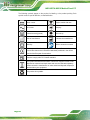
Manual Conventions
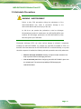
WARNING
Warnings appear where overlooked details may cause damage to the
equipment or result in personal injury. Warnings should be taken
seriously.
CAUTION
Cautionary messages should be heeded to help reduce the chance of
losing data or damaging the product.
NOTE
These messages inform the reader of essential but non-critical
information. These messages should be read carefully as any directions
or instructions contained therein can help avoid making mistakes.

IASO-W07A-N6210 Medical Panel PC
Page v
[MODEL NAME]
Table of Contents
1 INTRODUCTION .......................................................................................................... 1
1.1 OVERVIEW.................................................................................................................. 2
1.2 FEATURES ................................................................................................................... 3
1.3 FRONT PANEL............................................................................................................. 3
1.4 BOTTOM PANEL ......................................................................................................... 4
1.5 REAR PANEL .............................................................................................................. 5
1.6 SYSTEM SPECIFICATIONS ............................................................................................ 6
1.7 DIMENSIONS ............................................................................................................... 8
2 UNPACKING ................................................................................................................. 9
2.1 UNPACKING .............................................................................................................. 10
2.2 PACKING LIST ........................................................................................................... 11
3 INSTALLATION ......................................................................................................... 12
3.1 SAFETY PRECAUTIONS ............................................................................................. 13
3.2 ANTI-STATIC PRECAUTIONS ...................................................................................... 15
3.3 INSTALLATION PRECAUTIONS ................................................................................... 16
3.4 GBE CONNECTION ................................................................................................... 17
3.5 AT/ATX MODE SELECTION ...................................................................................... 18
3.6 VESA MOUNTING .................................................................................................... 19
3.7 POWERING ON THE SYSTEM ..................................................................................... 20
3.8 CLEAR CMOS .......................................................................................................... 22
3.9 RESET THE SYSTEM .................................................................................................. 22
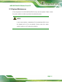
3.10 SYSTEM MAINTENANCE ......................................................................................... 23
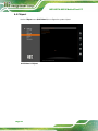
4 BIOS SETUP ................................................................................................................ 24
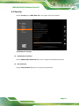
4.1 INTRODUCTION ......................................................................................................... 25
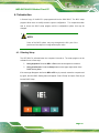
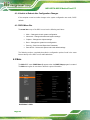
4.1.1 Starting Setup ................................................................................................... 25
4.1.2 Using Setup ...................................................................................................... 26
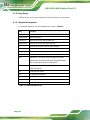
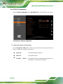
4.1.2.1 Keyboard Navigation ................................................................................ 26
4.1.2.2 Touch Navigation ...................................................................................... 27

IASO-W07A-N6210 Medical Panel PC
Page vi
[MODEL NAME]
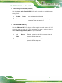
4.1.3 Getting Help ..................................................................................................... 27
4.1.4 Unable to Reboot after Configuration Changes .............................................. 28
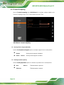
4.1.5 BIOS Menu Bar ................................................................................................ 28
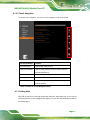
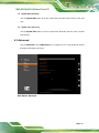
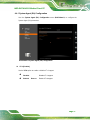
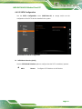
4.2 MAIN ........................................................................................................................ 28
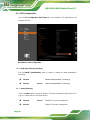
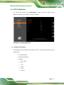
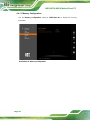
4.3 ADVANCED ............................................................................................................... 29
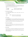
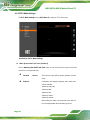
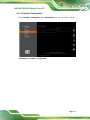
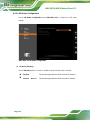
4.3.1 CPU Configuration .......................................................................................... 30
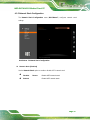
4.3.2 Trusted Computing ........................................................................................... 32
4.3.3 IT5571 H/W Monitor ........................................................................................ 33
4.3.4 RTC Wake Settings ........................................................................................... 34
4.3.5 Network Stack Configuration ........................................................................... 35
4.4 CHIPSET ................................................................................................................... 36
4.4.1 System Agent (SA) Configuration .................................................................... 37
4.4.1.1 Memory Configuration ............................................................................. 38
4.4.1.2 Graphics Configuration ............................................................................. 39
4.4.2 PCH-IO Configuration .................................................................................... 40
4.4.2.1 PCI Express Configuration ....................................................................... 42
4.4.2.2 SATA Configuration .................................................................................. 43
4.4.2.3 HD Audio Configuration ........................................................................... 44
4.5 SECURITY ................................................................................................................. 45
4.6 BOOT ........................................................................................................................ 46
4.7 SAVE & EXIT ............................................................................................................ 46
5 DRIVER INSTALLATION ......................................................................................... 48
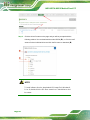
5.1 AVAILABLE DRIVERS................................................................................................ 49
5.2 DRIVER DOWNLOAD ................................................................................................ 49
A REGULATORY COMPLIANCE .............................................................................. 51
B PRODUCT DISPOSAL .............................................................................................. 56
C MAINTENANCE AND CLEANING PRECAUTIONS .......................................... 58
C.1.1 Maintenance and Cleaning ............................................................................. 60
C.1.2 Cleaning Tools ................................................................................................. 60
D SYMBOL DEFINITIONS .......................................................................................... 61
E WATCHDOG TIMER ................................................................................................. 63
F ERROR BEEP CODE ................................................................................................. 66

IASO-W07A-N6210 Medical Panel PC
Page vii
[MODEL NAME]
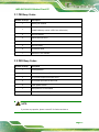
F.1 PEI BEEP CODES ...................................................................................................... 67
F.2 DXE BEEP CODES .................................................................................................... 67
G HAZARDOUS MATERIALS DISCLOSURE ......................................................... 68
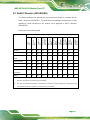
G.1 ROHS II DIRECTIVE (2015/863/EU) ....................................................................... 69
G.2 CHINA ROHS ........................................................................................................... 70

IASO-W07A-N6210 Medical Panel PC
Page viii
[MODEL NAME]
List of Figures
Figure 1-1: IASO-W07A-N6210 Medical Panel PC ....................................................................... 2
Figure 1-2: Front View .................................................................................................................... 3
Figure 1-3: Bottom Panel ............................................................................................................... 4
Figure 1-4: Rear View ..................................................................................................................... 5
Figure 1-5: Dimensions (mm) ........................................................................................................ 8
Figure 3-1: Ethernet Connector ...................................................................................................17
Figure 3-2: AT/ATX Switch Location ...........................................................................................18
Figure 3-3: VESA Mounting Retention Screw Holes .................................................................19
Figure 3-4: Power Input Connector and Power Button .............................................................20
Figure 3-5: Power LED .................................................................................................................21
Figure 3-6: Clear CMOS Button Location ...................................................................................22
Figure 3-7: Reset Button Location ..............................................................................................22
Figure 5-1: IEI Resource Download Center ................................................................................49

IASO-W07A-N6210 Medical Panel PC
Page ix
[MODEL NAME]
List of Tables
Table 1-1: System Specifications .................................................................................................. 7
Table 3-1: Ethernet Connector Pinouts ......................................................................................17
Table 3-2: Connector LEDs ..........................................................................................................17
Table 4-1: BIOS Navigation Keys ................................................................................................26
Table 4-2: BIOS On-screen Navigation Keys .............................................................................27


IASO-W07A-N6210 Medical Panel PC
Page 1
1 Introduction
Chapter
1

IASO-W07A-N6210 Medical Panel PC
Page 2
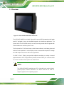
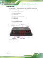
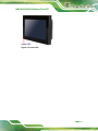
1.1 Overview
Figure 1-1: IASO-W07A-N6210 Medical Panel PC
The IASO-W07A-N6210 is an Intel® Celeron® Processor N6210 powered medical-grade
panel PC designed for easy and simplified integration into healthcare applications. The
system has 8 GB of LPDDR4x memory on board, ensuring smooth data throughputs with
reduced bottlenecks and fast system access.
The front panel is a P-CAP touchscreen, which allows multi-touch, multi-layer gloves and
water-on-screen operation. A second display can be connected with the panel PC through
the HDMI output connector for multi-screen applications.
Six USB 3.2 Gen 1 (5Gb/s) ports provide simplified connectivity to a variety of external
peripheral devices. Wi-Fi 6 high efficiency wireless and two GbE RJ-45 connectors allow
for smooth connection of the system to an external LAN.
NOTE:
The IASO-W07A-N6210 medical panel PC is intended to be used to display
general purpose medical information. The device shall not be used for
diagnosis purpose or life supporting system.

IASO-W07A-N6210 Medical Panel PC
Page 3
1.2 Features
The IASO-W07A-N6210 features are listed below:
Ultra-compact fanless medical-grade panel PC for easy installation
P-CAP touchscreen supports multi-touch, gloved and wet hand operation
Intel® Celeron® Processor N6210 platform
Onboard 8 GB LPDDR4x memory
One HDMI output port supports an additional display
Two GbE RJ-45 ports
Wi-Fi 6 high efficiency wireless
Internal speaker
Six USB 3.2 Gen 1 (5Gb/s) ports
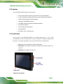
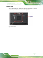
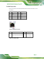
1.3 Front Panel
The front side of the IASO-W07A-N6210 is a flat-bezel panel with a 7" LCD screen
surrounded by an ABS/PC plastic frame. There is a power LED indicator located on the
front panel. The status descriptions of the power LED indicator are listed below.
Off: power cord not attached or power supply failure
Solid amber: the system is connected to a power source and is ready to be
turned on.
Solid green: the system is turned on.
Figure 1-2: Front View

IASO-W07A-N6210 Medical Panel PC
Page 4
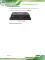
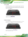
1.4 Bottom Panel
The bottom panel of the IASO-W07A-N6210 has the following connectors and
components (Figure 1-3):
1 x 12 V DC input jack (standard)
1 x HDMI output connector
2 x 1GbE RJ-45
6 x USB 3.2 Gen 1 connector (5Gb/s)
1 x Power button
1 x Reset button
1 x Clear CMOS button
1 x AT/ATX power mode switch
Figure 1-3: Bottom Panel


IASO-W07A-N6210 Medical Panel PC
Page 6
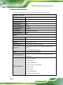
1.6 System Specifications
The technical specifications for the IASO-W07A-N6210 systems are listed below.
LCD and Touchscreen
LCD Size
7"
Max. Resolution
1024 (W) x 600 (H)
Brightness (cd/m2)
450
Contrast Ratio
800:1
Viewing Angle (H-V)
170°/170°
Backlight MTBF
20,000 hrs
Touchscreen
Projected capacitive type
Touch Controller
EETI
System
CPU
Intel® Celeron® N6210 (code-named Elkhart Lake, 6.5W TDP)
Memory
Onboard 8GB LPDDR4x
Storage
32GB eMMC on board
GbE Controller
2 x Intel® I225-V Ethernet controllers
Expansion
1 x M.2 2230 A key slot (PCIe + USB, pre-installed with Wi-Fi
module)
1 x M.2 2280 M key slot (SATA)
Audio
1 x AMP 1.5W (internal speaker)
Wi-Fi and Bluetooth
IEEE 802.11 a/b/g/n/ac/ax (Wi-Fi 6) via Intel® AX200 module
Bluetooth v5.2
I/O Ports & Buttons
1 x 12V DC input jack
1 x HDMI output
2 x 1GbE LAN (RJ-45)
6 x USB 3.2 Gen 1 Type-A (5Gb/s)
1 x Power button
1 x Reset button
1 x Clear CMOS button
1 x AT/ATX power mode switch

IASO-W07A-N6210 Medical Panel PC
Page 7
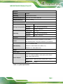
Physical
Thermal
Fanless
Mounting
VESA 75 mm x 75 mm
Dimensions (W x H x D)
190.9 mm x 127.3 mm x 43.4 mm
Weight (Net/Gross)
0.72 kg / 1.65 kg
Environment
Storage/Transportation
Temperature
-20ºC - 60ºC
Humidity
10% - 95% (non-condensing)
Pressure
700 hPa - 1060 hPa
Operating
Temperature
0ºC - 40ºC
Humidity
20% - 80% (non-condensing)
Pressure
700 hPa - 1060 hPa
Vibration
1G
Shock
Operating Shock: 5G peak acceleration (11ms duration)
Non-Operating Shock: 15G peak acceleration (11ms duration)
EMC & Safety
CE, FCC Class B Part18
EN 60601-1:2005+AMD2:2021 (Edition 3.2)
EN 60601-1-2: 2014 (Edition 4.0)
Power
Power Input
12 V DC
Power Adapter
65 W FSP FSP065-DHBM1 medical-grade power adapter
(P/N: 63040-010065-300-RS)
Input: 100 V AC - 240 V AC, 50 Hz - 60 Hz, 2.0 A – 1.0 A
Output: 12 V 5.42 A
Table 1-1: System Specifications

IASO-W07A-N6210 Medical Panel PC
Page 8
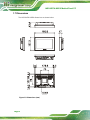
1.7 Dimensions
The IASO-W07A-N6210 dimensions are shown below.
Figure 1-5: Dimensions (mm)

IASO-W07A-N6210 Medical Panel PC
Page 9
2 Unpacking
Chapter
2

IASO-W07A-N6210 Medical Panel PC
Page 10
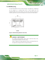
2.1 Unpacking
To unpack the medical panel PC, follow the steps below:
WARNING / AVERTISSEMENT
The front side LCD screen has a protective plastic cover stuck to the
screen. Only remove the plastic cover after the medical panel PC has been
properly installed. This ensures the screen is protected during the
installation process.
L'écran LCD avant a un couvercle en plastique de protection collé à l'écran.
Retirez le couvercle en plastique uniquement une fois que le Panel PC
médical a été correctement installé. Cela garantit que l'écran est protégé
pendant le processus d'installation.
Step 1: Use box cutters, a knife or a sharp pair of scissors that seals the top side of the
external (second) box.
Step 2: Open the external (second) box.
Step 3: Use box cutters, a knife or a sharp pair of scissors that seals the top side of the
internal (first) box.
Step 4: Lift the panel PC out of the boxes.
Step 5: Remove both polystyrene ends, one from each side.
Step 6: Pull the plastic cover off the medical panel PC.
Step 7: Make sure all the components listed in the packing list are present.
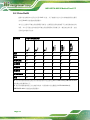
Step 0:
La pagina si sta caricando...
La pagina si sta caricando...
La pagina si sta caricando...
La pagina si sta caricando...
La pagina si sta caricando...
La pagina si sta caricando...
La pagina si sta caricando...
La pagina si sta caricando...
La pagina si sta caricando...
La pagina si sta caricando...
La pagina si sta caricando...
La pagina si sta caricando...
La pagina si sta caricando...
La pagina si sta caricando...
La pagina si sta caricando...
La pagina si sta caricando...
La pagina si sta caricando...
La pagina si sta caricando...
La pagina si sta caricando...
La pagina si sta caricando...
La pagina si sta caricando...
La pagina si sta caricando...
La pagina si sta caricando...
La pagina si sta caricando...
La pagina si sta caricando...
La pagina si sta caricando...
La pagina si sta caricando...
La pagina si sta caricando...
La pagina si sta caricando...
La pagina si sta caricando...
La pagina si sta caricando...
La pagina si sta caricando...
La pagina si sta caricando...
La pagina si sta caricando...
La pagina si sta caricando...
La pagina si sta caricando...
La pagina si sta caricando...
La pagina si sta caricando...
La pagina si sta caricando...
La pagina si sta caricando...
La pagina si sta caricando...
La pagina si sta caricando...
La pagina si sta caricando...
La pagina si sta caricando...
La pagina si sta caricando...
La pagina si sta caricando...
La pagina si sta caricando...
La pagina si sta caricando...
La pagina si sta caricando...
La pagina si sta caricando...
La pagina si sta caricando...
La pagina si sta caricando...
La pagina si sta caricando...
La pagina si sta caricando...
La pagina si sta caricando...
La pagina si sta caricando...
La pagina si sta caricando...
La pagina si sta caricando...
La pagina si sta caricando...
La pagina si sta caricando...
-
 1
1
-
 2
2
-
 3
3
-
 4
4
-
 5
5
-
 6
6
-
 7
7
-
 8
8
-
 9
9
-
 10
10
-
 11
11
-
 12
12
-
 13
13
-
 14
14
-
 15
15
-
 16
16
-
 17
17
-
 18
18
-
 19
19
-
 20
20
-
 21
21
-
 22
22
-
 23
23
-
 24
24
-
 25
25
-
 26
26
-
 27
27
-
 28
28
-
 29
29
-
 30
30
-
 31
31
-
 32
32
-
 33
33
-
 34
34
-
 35
35
-
 36
36
-
 37
37
-
 38
38
-
 39
39
-
 40
40
-
 41
41
-
 42
42
-
 43
43
-
 44
44
-
 45
45
-
 46
46
-
 47
47
-
 48
48
-
 49
49
-
 50
50
-
 51
51
-
 52
52
-
 53
53
-
 54
54
-
 55
55
-
 56
56
-
 57
57
-
 58
58
-
 59
59
-
 60
60
-
 61
61
-
 62
62
-
 63
63
-
 64
64
-
 65
65
-
 66
66
-
 67
67
-
 68
68
-
 69
69
-
 70
70
-
 71
71
-
 72
72
-
 73
73
-
 74
74
-
 75
75
-
 76
76
-
 77
77
-
 78
78
-
 79
79
-
 80
80


IEI Integration IASO-W07A-N6210 Manuale utente
- Tipo
- Manuale utente
in altre lingue
Documenti correlati
Altri documenti
-
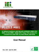 IEI Technology PUZZLE-M801 Manuale utente
-
Intel D945PVS Manuale utente
-
Intel BOXD945PSNLK Manuale utente
-
-
Asus P12R-M/10G-2T Manuale utente
-
Asus ProArt B760-CREATOR Manuale utente
-
Gigabyte W480 VISION D Manuale del proprietario
-
Asus ProArt B760-CREATOR WIFI Manuale utente
