
NFX350 Network Services Platform
Hardware Guide
Published
2020-03-23

Juniper Networks, Inc.
1133 Innovation Way
Sunnyvale, California 94089
USA
408-745-2000
www.juniper.net
Juniper Networks, the Juniper Networks logo, Juniper, and Junos are registered trademarks of Juniper Networks, Inc. in
the United States and other countries. All other trademarks, service marks, registered marks, or registered service marks
are the property of their respective owners.
Juniper Networks assumes no responsibility for any inaccuracies in this document. Juniper Networks reserves the right
to change, modify, transfer, or otherwise revise this publication without notice.
NFX350 Network Services Platform Hardware Guide
Copyright © 2020 Juniper Networks, Inc. All rights reserved.
The information in this document is current as of the date on the title page.
YEAR 2000 NOTICE
Juniper Networks hardware and software products are Year 2000 compliant. Junos OS has no known time-related
limitations through the year 2038. However, the NTP application is known to have some difficulty in the year 2036.
END USER LICENSE AGREEMENT
The Juniper Networks product that is the subject of this technical documentation consists of (or is intended for use with)
Juniper Networks software. Use of such software is subject to the terms and conditions of the End User License Agreement
(“EULA”) posted at https://support.juniper.net/support/eula/. By downloading, installing or using such software, you
agree to the terms and conditions of that EULA.
ii

Table of Contents
About the Documentation | x
Documentation and Release Notes | x
Using the Examples in This Manual | x
Merging a Full Example | xi
Merging a Snippet | xii
Documentation Conventions | xii
Documentation Feedback | xv
Requesting Technical Support | xv
Self-Help Online Tools and Resources | xvi
Creating a Service Request with JTAC | xvi
Overview
1
NFX350 Network Services Platform Overview | 18
NFX350 Hardware | 19
System Software | 19
Junos OS Releases Supported on NFX Series Hardware | 19
NFX350 Device Models | 20
Benefits and Uses of NFX350 | 23
NFX350 Chassis | 24
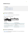
Front Panel of an NFX350 Device | 24
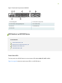
Rear Panel of an NFX350 Device | 24
LED Details of an NFX350 Device | 25
Chassis Status LEDs | 25
Network Port and Uplink Port LEDs | 27
Management Port LEDs | 27
iii

LTE Module LEDs | 29
NFX350 Interface Modules | 30
LTE on NFX350 Devices | 30
Overview | 30
Features Supported on the LTE Module for NFX Devices | 31
Understanding the LTE Physical Interface | 32
Understanding the LTE Logical Interface | 32
LTE Expansion Module (NFX-LTE-AE and NFX-LTE-AA) | 33
NFX350 Cooling System | 35
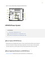
NFX350 Power System | 36
Power Supply in NFX350 Devices | 36
Power Supply Specifications for an NFX350 Device | 36
AC Power Cord Specifications for an NFX350 Device | 38
Site Planning, Preparation, and Specifications
2
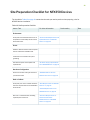
Site Preparation Checklist for NFX350 Devices | 42
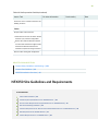
NFX350 Site Guidelines and Requirements | 43
General Site Guidelines | 44
Chassis Physical Specifications for an NFX350 Device | 44
Environmental Requirements and Specifications for an NFX350 Device | 44
Site Electrical Wiring Guidelines | 45
Clearance Requirements for Airflow and Hardware Maintenance for an NFX350 Device | 46
Rack Requirements for NFX350 Devices | 47
iv

Cabinet Requirements for an NFX350 Device | 49
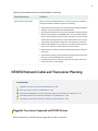
NFX350 Network Cable and Transceiver Planning | 50
Pluggable Transceivers Supported on NFX350 Devices | 50
SFP+ Direct Attach Cables for NFX350 Devices | 51
Cable Specifications | 52
Standards Supported by DAC Cables | 52
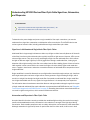
Understanding NFX350 Devices Fiber-Optic Cable Signal Loss, Attenuation, and
Dispersion | 53
Signal Loss in Multimode and Single-Mode Fiber-Optic Cables | 53
Attenuation and Dispersion in Fiber-Optic Cable | 53
Calculating the Fiber-Optic Cable Power Budget for an NFX350 Device | 54
Calculating the Fiber-Optic Cable Power Margin for an NFX350 Device | 55
NFX350 Cable Specifications and Pinouts | 57
Cable Specifications for Console and Management Connections for the NFX350 Devices | 57
Mini-USB Type-B Console Port Specifications for an NFX350 Device | 58
Console Port Connector Pinouts for NFX350 Devices | 58
USB Port Specifications for an NFX350 Device | 59
Management Port Connector Pinout Information for an NFX350 Device | 60
Network Port Connector Pinout Information for an NFX350 Device | 61
RJ-45 to DB-9 Serial Port Adapter Pinout Information for an NFX350 Device | 62
Initial Installation and Configuration
3
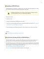
NFX350 Installation Overview | 64
Unpacking and Mounting the NFX350 | 64
Unpacking an NFX350 Device | 65
Parts Inventory (Packing List) for an NFX350 Device | 65
Registering Products—Mandatory for Validating SLAs | 66
Mounting an NFX350 Device | 67
v

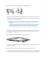
Mounting an NFX350 Device on Four Posts in a Rack or Cabinet | 67
Connecting the NFX350 to Power | 71
Connecting Earth Ground to an NFX350 Device | 71
Parts and Tools Required for Connecting an NFX350 Device to Earth Ground | 72
Connecting Earth Ground to an NFX350 Device | 72
Connecting AC Power to an NFX350 Device | 73
Connecting DC Power to an NFX350 Device | 75
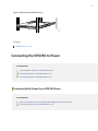
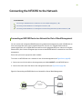
Connecting the NFX350 to the Network | 80
Connecting an NFX350 Device to a Network for Out-of-Band Management | 80
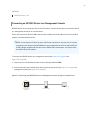
Connecting an NFX350 Device to a Management Console | 81
Connecting an NFX350 Device to a Management Console Using Mini-USB Type-B Console
Port | 82
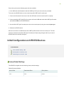
Initial Configuration on NFX350 Devices | 83
Factory Default Settings | 83
Enabling Basic Connectivity | 84
Establishing the Connection | 86
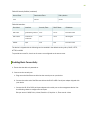
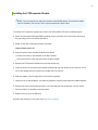
Installing and Configuring the NFX350 Expansion Modules | 86
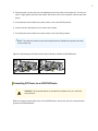
Installing the LTE Expansion Module | 87
Configuring the LTE Expansion Module | 88
Configuring the LTE Expansion Module for Primary Mode | 89
Configuring the LTE Expansion Module for Dial-on-Demand Mode | 90
Configuring the LTE Expansion Module for Backup Mode | 92
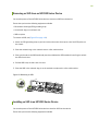
Upgrading the Modem Firmware on NFX Devices Through Over-the-Air (OTA) | 94
Maintaining Components
4
Maintaining the NFX350 Cooling System | 98
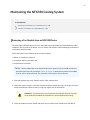
Removing a Fan Module from an NFX350 Device | 98
Installing a Fan Module in an NFX350 Device | 99
Maintaining Transceivers on the NFX350 | 101
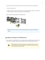
Installing a Transceiver in an NFX350 Device | 101
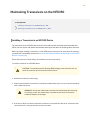
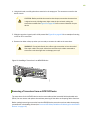
Removing a Transceiver from an NFX350 Device | 102
vi

Maintaining Fiber-Optic Cables on the NFX350 | 104
Maintaining Fiber-Optic Cables in an NFX350 Device | 104
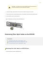
Disconnecting a Fiber-Optic Cable from an NFX350 Device | 105
Connecting a Fiber-Optic Cable to an NFX350 Device | 106
Removing the NFX350 Device from a Rack or Cabinet | 108
Powering off an NFX350 Device | 108
Removing an NFX350 Device from a Rack or Cabinet | 110
Maintaining the NFX350 SSD | 111
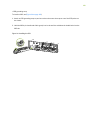
Removing an SSD from an NFX350 Series Device | 112
Installing an SSD in an NFX350 Series Device | 112
Troubleshooting Hardware
5
Understanding Alarm Types and Severity Levels on NFX350 Devices | 115
Contacting Customer Support and Returning the Chassis or Components
6
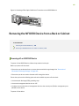
Returning the NFX350 Chassis or Components | 117
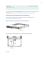
Returning a NFX350 Device or Component for Repair or Replacement | 117
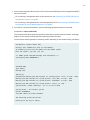
Locating the Serial Number on an NFX350 Device | 118
Listing the Device and Components Details with the CLI | 118
Locating the Chassis Serial Number ID Label on an NFX350 Device | 119
Contacting Customer Support to Obtain a Return Materials Authorization for an NFX350
Device | 120
Packing NFX350 Device Components for Shipping | 121
Safety and Compliance Information
7
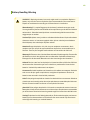
General Safety Guidelines and Warnings | 124
Definitions of Safety Warning Levels | 125
Qualified Personnel Warning | 128
Warning Statement for Norway and Sweden | 129
Fire Safety Requirements | 129
Fire Suppression | 129
Fire Suppression Equipment | 129
vii

Installation Instructions Warning | 131
Chassis Lifting Guidelines for NFX350 Devices | 131
Restricted Access Warning | 133
Ramp Warning | 135
Rack-Mounting and Cabinet-Mounting Warnings | 136
Laser and LED Safety Guidelines and Warnings for the NFX350 Devices | 141
General Laser Safety Guidelines | 142
Class 1M Laser Product Warning | 143
Class 1M Laser Radiation Warning | 143
Class 1 Laser Product Warning | 144
Class 1 LED Product Warning | 145
Laser Beam Warning | 146
Unterminated Fiber-Optic Cable Warning | 147
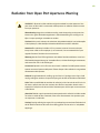
Radiation from Open Port Apertures Warning | 150
Maintenance and Operational Safety Guidelines and Warnings | 151
Battery Handling Warning | 152
Jewelry Removal Warning | 153
Lightning Activity Warning | 155
Operating Temperature Warning | 156
Product Disposal Warning | 158
General Electrical Safety Guidelines and Warnings | 159
Action to Take After an Electrical Accident | 160
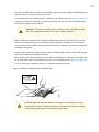
Prevention of Electrostatic Discharge Damage | 160
AC Power Electrical Safety Guidelines | 162
AC Power Disconnection Warning | 163
viii


About the Documentation
IN THIS SECTION
Documentation and Release Notes | x
Using the Examples in This Manual | x
Documentation Conventions | xii
Documentation Feedback | xv
Requesting Technical Support | xv
Use this guide to install hardware and perform initial software configuration, routine maintenance, and
troubleshooting for the NFX350 Series devices. After completing the installation and basic configuration
procedures covered in this guide, refer to the How to Configure NFX350 guide for information about
further software configuration.
Documentation and Release Notes
To obtain the most current version of all Juniper Networks
®
technical documentation, see the product
documentation page on the Juniper Networks website at https://www.juniper.net/documentation/.
If the information in the latest release notes differs from the information in the documentation, follow the
product Release Notes.
Juniper Networks Books publishes books by Juniper Networks engineers and subject matter experts.
These books go beyond the technical documentation to explore the nuances of network architecture,
deployment, and administration. The current list can be viewed at https://www.juniper.net/books.
Using the Examples in This Manual
If you want to use the examples in this manual, you can use the load merge or the load merge relative
command. These commands cause the software to merge the incoming configuration into the current
candidate configuration. The example does not become active until you commit the candidate configuration.
x

If the example configuration contains the top level of the hierarchy (or multiple hierarchies), the example
is a full example. In this case, use the load merge command.
If the example configuration does not start at the top level of the hierarchy, the example is a snippet. In
this case, use the load merge relative command. These procedures are described in the following sections.
Merging a Full Example
To merge a full example, follow these steps:
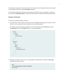
1. From the HTML or PDF version of the manual, copy a configuration example into a text file, save the
file with a name, and copy the file to a directory on your routing platform.
For example, copy the following configuration to a file and name the file ex-script.conf. Copy the
ex-script.conf file to the /var/tmp directory on your routing platform.
system {
scripts {
commit {
file ex-script.xsl;
}
}
}
interfaces {
fxp0 {
disable;
unit 0 {
family inet {
address 10.0.0.1/24;
}
}
}
}
2. Merge the contents of the file into your routing platform configuration by issuing the load merge
configuration mode command:
[edit]
user@host# load merge /var/tmp/ex-script.conf
load complete
xi

Merging a Snippet
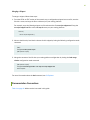
To merge a snippet, follow these steps:
1. From the HTML or PDF version of the manual, copy a configuration snippet into a text file, save the
file with a name, and copy the file to a directory on your routing platform.
For example, copy the following snippet to a file and name the file ex-script-snippet.conf. Copy the
ex-script-snippet.conf file to the /var/tmp directory on your routing platform.
commit {
file ex-script-snippet.xsl; }
2. Move to the hierarchy level that is relevant for this snippet by issuing the following configuration mode
command:
[edit]
user@host# edit system scripts
[edit system scripts]
3. Merge the contents of the file into your routing platform configuration by issuing the load merge
relative configuration mode command:
[edit system scripts]
user@host# load merge relative /var/tmp/ex-script-snippet.conf
load complete
For more information about the load command, see CLI Explorer.
Documentation Conventions
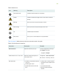
Table 1 on page xiii defines notice icons used in this guide.
xii

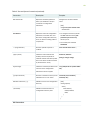
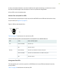
Table 1: Notice Icons
DescriptionMeaningIcon
Indicates important features or instructions.Informational note
Indicates a situation that might result in loss of data or hardware
damage.
Caution
Alerts you to the risk of personal injury or death.Warning
Alerts you to the risk of personal injury from a laser.Laser warning
Indicates helpful information.Tip
Alerts you to a recommended use or implementation.Best practice
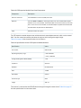
Table 2 on page xiii defines the text and syntax conventions used in this guide.
Table 2: Text and Syntax Conventions
ExamplesDescriptionConvention
To enter configuration mode, type
the configure command:
user@host> configure
Represents text that you type.Bold text like this
user@host> show chassis alarms
No alarms currently active
Represents output that appears on
the terminal screen.
Fixed-width text like this
•
A policy term is a named structure
that defines match conditions and
actions.
•
Junos OS CLI User Guide
•
RFC 1997, BGP Communities
Attribute
•
Introduces or emphasizes important
new terms.
•
Identifies guide names.
•
Identifies RFC and Internet draft
titles.
Italic text like this
xiii

Table 2: Text and Syntax Conventions (continued)
ExamplesDescriptionConvention
Configure the machine’s domain
name:
[edit]
root@# set system domain-name
domain-name
Represents variables (options for
which you substitute a value) in
commands or configuration
statements.
Italic text like this
•
To configure a stub area, include
the stub statement at the [edit
protocols ospf area area-id]
hierarchy level.
•
The console port is labeled
CONSOLE.
Represents names of configuration
statements, commands, files, and
directories; configuration hierarchy
levels; or labels on routing platform
components.
Text like this
stub <default-metric metric>;Encloses optional keywords or
variables.
< > (angle brackets)
broadcast | multicast
(string1 | string2 | string3)
Indicates a choice between the
mutually exclusive keywords or
variables on either side of the symbol.
The set of choices is often enclosed
in parentheses for clarity.
| (pipe symbol)
rsvp { # Required for dynamic MPLS
only
Indicates a comment specified on the
same line as the configuration
statement to which it applies.
# (pound sign)
community name members [
community-ids ]
Encloses a variable for which you can
substitute one or more values.
[ ] (square brackets)
[edit]
routing-options {
static {
route default {
nexthop address;
retain;
}
}
}
Identifies a level in the configuration
hierarchy.
Indention and braces ( { } )
Identifies a leaf statement at a
configuration hierarchy level.
; (semicolon)
GUI Conventions
xiv

Table 2: Text and Syntax Conventions (continued)
ExamplesDescriptionConvention
•
In the Logical Interfaces box, select
All Interfaces.
•
To cancel the configuration, click
Cancel.
Represents graphical user interface
(GUI) items you click or select.
Bold text like this
In the configuration editor hierarchy,
select Protocols>Ospf.
Separates levels in a hierarchy of
menu selections.
> (bold right angle bracket)
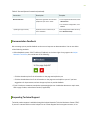
Documentation Feedback
We encourage you to provide feedback so that we can improve our documentation. You can use either
of the following methods:
•
Online feedback system—Click TechLibrary Feedback, on the lower right of any page on the Juniper
Networks TechLibrary site, and do one of the following:
•
Click the thumbs-up icon if the information on the page was helpful to you.
•
Click the thumbs-down icon if the information on the page was not helpful to you or if you have
suggestions for improvement, and use the pop-up form to provide feedback.
•
URL or page number, and software version (if applicable).
Requesting Technical Support
Technical product support is available through the Juniper Networks Technical Assistance Center (JTAC).
If you are a customer with an active Juniper Care or Partner Support Services support contract, or are
xv

covered under warranty, and need post-sales technical support, you can access our tools and resources
online or open a case with JTAC.
•
JTAC policies—For a complete understanding of our JTAC procedures and policies, review the JTAC User
Guide located at https://www.juniper.net/us/en/local/pdf/resource-guides/7100059-en.pdf.
•
Product warranties—For product warranty information, visit https://www.juniper.net/support/warranty/.
•
JTAC hours of operation—The JTAC centers have resources available 24 hours a day, 7 days a week,
365 days a year.
Self-Help Online Tools and Resources
For quick and easy problem resolution, Juniper Networks has designed an online self-service portal called
the Customer Support Center (CSC) that provides you with the following features:
•
Find CSC offerings: https://www.juniper.net/customers/support/
•
Search for known bugs: https://prsearch.juniper.net/
•
Find product documentation: https://www.juniper.net/documentation/
•
Find solutions and answer questions using our Knowledge Base: https://kb.juniper.net/
•
Download the latest versions of software and review release notes:
https://www.juniper.net/customers/csc/software/
•
Search technical bulletins for relevant hardware and software notifications:
https://kb.juniper.net/InfoCenter/
•
Join and participate in the Juniper Networks Community Forum:
https://www.juniper.net/company/communities/
•
Create a service request online: https://myjuniper.juniper.net
To verify service entitlement by product serial number, use our Serial Number Entitlement (SNE) Tool:
https://entitlementsearch.juniper.net/entitlementsearch/
Creating a Service Request with JTAC
You can create a service request with JTAC on the Web or by telephone.
•
Visit https://myjuniper.juniper.net.
•
Call 1-888-314-JTAC (1-888-314-5822 toll-free in the USA, Canada, and Mexico).
For international or direct-dial options in countries without toll-free numbers, see
https://support.juniper.net/support/requesting-support/.
xvi


NFX350 Network Services Platform Overview
IN THIS SECTION
NFX350 Hardware | 19
System Software | 19
Junos OS Releases Supported on NFX Series Hardware | 19
NFX350 Device Models | 20
Benefits and Uses of NFX350 | 23
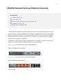
The Juniper Networks NFX350 Network Services Platform is a secure, automated, software-driven universal
customer premises equipment (uCPE) platform that delivers virtualized network and security services on
demand. Leveraging Network Functions Virtualization (NFV) and built on the Juniper Cloud CPE solution,
NFX350 enables service providers to deploy and chain multiple, secure, high-performance virtualized
network functions (VNFs) on a single device.
The NFX350 is suited for large and extra-large deployments. The NFX350 is a high-end resilient uCPE
platform that can be used in secure SD-WAN and secure router deployments.
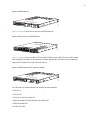
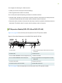
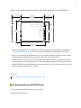
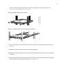
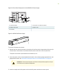
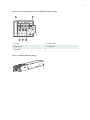
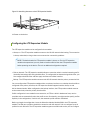
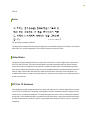
Figure 1 on page 18 shows the front panel of the NFX350 device.
Figure 1: Front Panel View of NFX350
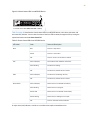
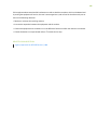
Figure 2 on page 18 shows the rear panel of the NFX350 device.
Figure 2: Rear Panel View of NFX350
This topic covers:
18

NFX350 Hardware
The NFX350 portfolio consists of rack-mount models, with LTE support. The NFX350 device has a 1 U
form factor and comes with built-in fans and power supply.
The NFX350 device can be used as:
•
A SD-WAN solution.
•
A resilient uCPE platform.
•
An integrated branch router and switch, extensible with VNFs.
•
A CPE for service providers.
•
A secure router for distributed enterprises.
System Software
The NFX350 architecture integrates routing, switching, and security functions on a single platform that
optimizes the usage of system resources. The architecture enables unified management of all the
components through a single CLI. Key components in the NFX350 software include the Junos Control
Plane (JCP), Juniper Device Manager (JDM), Layer 2 dataplane, Layer 3 dataplane, and Virtual Network
Functions (VNFs). The JCP is the Junos virtual machine (VM) running on the host OS, Wind River Linux.
The JCP functions as the single point of management for all the components. The JCP CLI is displayed
when you log in to the NFX350 device.
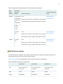
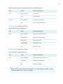
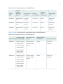
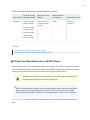
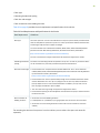
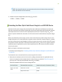
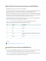
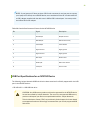
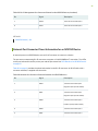
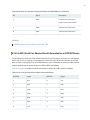
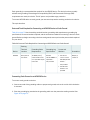
Junos OS Releases Supported on NFX Series Hardware
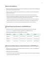
The following table provides details of Junos OS software releases supported on the NFX Series platforms:
Table 3: Supported Junos OS Releases on NFX Series Devices
Software Downloads
PageSoftware Package
Supported
Junos OS
Release
NFX
Series
Platform
NFX150 Software
Download Page
nfx-3
jinstall-host-nfx-3-x86-64-<release-number>- secure-signed.tgz
install-media-host-usb-nfx-3-x86-64-<release-number>- secure.img
18.1R1 or
later
NFX150
19

Table 3: Supported Junos OS Releases on NFX Series Devices (continued)
Software Downloads
PageSoftware Package
Supported
Junos OS
Release
NFX
Series
Platform
NFX250 Software
Download Page
nfx-2
jinstall-host-nfx-2-flex-x86-64-<release-number >-secure-signed.tgz
install-media-host-usb-nfx-2-flex-x86-64-<release-number>-secure.img
15.1X53-D45,
15.1X53-D47,
15.1X53-D470,
and
15.1X53-D471
NFX250
17.2R1
through
19.1R1
NFX250 Software
Download Page
nfx-3
jinstall-host-nfx-3-x86-64-<release-number>-secure-signed.tgz
install-media-host-usb-nfx-3-x86-64-<release-number>-secure.img
19.1 R1 or
later
NFX350 Software
Download Page
nfx-3
jinstall-host-nfx-3-x86-64-<release-number>-secure-signed.tgz
install-media-host-usb-nfx-3-x86-64-<release-number>-secure.img
19.4 R1 or
later
NFX350
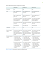
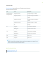
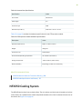
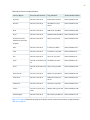
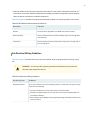
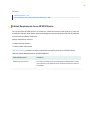
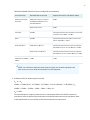
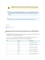
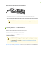
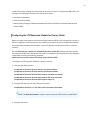
NFX350 Device Models
The NFX350 device is available in three models, with LTE support. All models are shipped with built-in AC
power supply and have airflow-out (front-to-back) cooling.
Table 4 on page 20 lists the NFX350 Series device models with device configurations.
Table 4: NFX350 Series Device Configurations
NFX350-S3NFX350-S2NFX350-S1
16-core Intel Skylake
D-2187NT
12-core Intel Skylake
D-2166NT
8-core Intel Skylake
D-2146NT
CPU
128GB64GB32GBRAM
100 GB SSD100 GB SSD100 GB SSDStorage
20
La pagina si sta caricando...
La pagina si sta caricando...
La pagina si sta caricando...
La pagina si sta caricando...
La pagina si sta caricando...
La pagina si sta caricando...
La pagina si sta caricando...
La pagina si sta caricando...
La pagina si sta caricando...
La pagina si sta caricando...
La pagina si sta caricando...
La pagina si sta caricando...
La pagina si sta caricando...
La pagina si sta caricando...
La pagina si sta caricando...
La pagina si sta caricando...
La pagina si sta caricando...
La pagina si sta caricando...
La pagina si sta caricando...
La pagina si sta caricando...
La pagina si sta caricando...
La pagina si sta caricando...
La pagina si sta caricando...
La pagina si sta caricando...
La pagina si sta caricando...
La pagina si sta caricando...
La pagina si sta caricando...
La pagina si sta caricando...
La pagina si sta caricando...
La pagina si sta caricando...
La pagina si sta caricando...
La pagina si sta caricando...
La pagina si sta caricando...
La pagina si sta caricando...
La pagina si sta caricando...
La pagina si sta caricando...
La pagina si sta caricando...
La pagina si sta caricando...
La pagina si sta caricando...
La pagina si sta caricando...
La pagina si sta caricando...
La pagina si sta caricando...
La pagina si sta caricando...
La pagina si sta caricando...
La pagina si sta caricando...
La pagina si sta caricando...
La pagina si sta caricando...
La pagina si sta caricando...
La pagina si sta caricando...
La pagina si sta caricando...
La pagina si sta caricando...
La pagina si sta caricando...
La pagina si sta caricando...
La pagina si sta caricando...
La pagina si sta caricando...
La pagina si sta caricando...
La pagina si sta caricando...
La pagina si sta caricando...
La pagina si sta caricando...
La pagina si sta caricando...
La pagina si sta caricando...
La pagina si sta caricando...
La pagina si sta caricando...
La pagina si sta caricando...
La pagina si sta caricando...
La pagina si sta caricando...
La pagina si sta caricando...
La pagina si sta caricando...
La pagina si sta caricando...
La pagina si sta caricando...
La pagina si sta caricando...
La pagina si sta caricando...
La pagina si sta caricando...
La pagina si sta caricando...
La pagina si sta caricando...
La pagina si sta caricando...
La pagina si sta caricando...
La pagina si sta caricando...
La pagina si sta caricando...
La pagina si sta caricando...
La pagina si sta caricando...
La pagina si sta caricando...
La pagina si sta caricando...
La pagina si sta caricando...
La pagina si sta caricando...
La pagina si sta caricando...
La pagina si sta caricando...
La pagina si sta caricando...
La pagina si sta caricando...
La pagina si sta caricando...
La pagina si sta caricando...
La pagina si sta caricando...
La pagina si sta caricando...
La pagina si sta caricando...
La pagina si sta caricando...
La pagina si sta caricando...
La pagina si sta caricando...
La pagina si sta caricando...
La pagina si sta caricando...
La pagina si sta caricando...
La pagina si sta caricando...
La pagina si sta caricando...
La pagina si sta caricando...
La pagina si sta caricando...
La pagina si sta caricando...
La pagina si sta caricando...
La pagina si sta caricando...
La pagina si sta caricando...
La pagina si sta caricando...
La pagina si sta caricando...
La pagina si sta caricando...
La pagina si sta caricando...
La pagina si sta caricando...
La pagina si sta caricando...
La pagina si sta caricando...
La pagina si sta caricando...
La pagina si sta caricando...
La pagina si sta caricando...
La pagina si sta caricando...
La pagina si sta caricando...
La pagina si sta caricando...
La pagina si sta caricando...
La pagina si sta caricando...
La pagina si sta caricando...
La pagina si sta caricando...
La pagina si sta caricando...
La pagina si sta caricando...
La pagina si sta caricando...
La pagina si sta caricando...
La pagina si sta caricando...
La pagina si sta caricando...
La pagina si sta caricando...
La pagina si sta caricando...
La pagina si sta caricando...
La pagina si sta caricando...
La pagina si sta caricando...
La pagina si sta caricando...
La pagina si sta caricando...
La pagina si sta caricando...
La pagina si sta caricando...
La pagina si sta caricando...
La pagina si sta caricando...
La pagina si sta caricando...
La pagina si sta caricando...
La pagina si sta caricando...
La pagina si sta caricando...
La pagina si sta caricando...
La pagina si sta caricando...
La pagina si sta caricando...
-
 1
1
-
 2
2
-
 3
3
-
 4
4
-
 5
5
-
 6
6
-
 7
7
-
 8
8
-
 9
9
-
 10
10
-
 11
11
-
 12
12
-
 13
13
-
 14
14
-
 15
15
-
 16
16
-
 17
17
-
 18
18
-
 19
19
-
 20
20
-
 21
21
-
 22
22
-
 23
23
-
 24
24
-
 25
25
-
 26
26
-
 27
27
-
 28
28
-
 29
29
-
 30
30
-
 31
31
-
 32
32
-
 33
33
-
 34
34
-
 35
35
-
 36
36
-
 37
37
-
 38
38
-
 39
39
-
 40
40
-
 41
41
-
 42
42
-
 43
43
-
 44
44
-
 45
45
-
 46
46
-
 47
47
-
 48
48
-
 49
49
-
 50
50
-
 51
51
-
 52
52
-
 53
53
-
 54
54
-
 55
55
-
 56
56
-
 57
57
-
 58
58
-
 59
59
-
 60
60
-
 61
61
-
 62
62
-
 63
63
-
 64
64
-
 65
65
-
 66
66
-
 67
67
-
 68
68
-
 69
69
-
 70
70
-
 71
71
-
 72
72
-
 73
73
-
 74
74
-
 75
75
-
 76
76
-
 77
77
-
 78
78
-
 79
79
-
 80
80
-
 81
81
-
 82
82
-
 83
83
-
 84
84
-
 85
85
-
 86
86
-
 87
87
-
 88
88
-
 89
89
-
 90
90
-
 91
91
-
 92
92
-
 93
93
-
 94
94
-
 95
95
-
 96
96
-
 97
97
-
 98
98
-
 99
99
-
 100
100
-
 101
101
-
 102
102
-
 103
103
-
 104
104
-
 105
105
-
 106
106
-
 107
107
-
 108
108
-
 109
109
-
 110
110
-
 111
111
-
 112
112
-
 113
113
-
 114
114
-
 115
115
-
 116
116
-
 117
117
-
 118
118
-
 119
119
-
 120
120
-
 121
121
-
 122
122
-
 123
123
-
 124
124
-
 125
125
-
 126
126
-
 127
127
-
 128
128
-
 129
129
-
 130
130
-
 131
131
-
 132
132
-
 133
133
-
 134
134
-
 135
135
-
 136
136
-
 137
137
-
 138
138
-
 139
139
-
 140
140
-
 141
141
-
 142
142
-
 143
143
-
 144
144
-
 145
145
-
 146
146
-
 147
147
-
 148
148
-
 149
149
-
 150
150
-
 151
151
-
 152
152
-
 153
153
-
 154
154
-
 155
155
-
 156
156
-
 157
157
-
 158
158
-
 159
159
-
 160
160
-
 161
161
-
 162
162
-
 163
163
-
 164
164
-
 165
165
-
 166
166
-
 167
167
-
 168
168
-
 169
169


in altre lingue
- English: Juniper NFX350 User manual
Documenti correlati
-
Juniper PTX1000 Manuale utente
-
Juniper MX10016 Manuale utente
-
-
-
-
Juniper QFX5120-48Y-AFI2 Manuale utente
-
Juniper MX204 Manuale utente
-
-
-
Altri documenti
-
DeLOCK 86234 Scheda dati
-
Yamaha SWR2311P-10G Manuale del proprietario
-
ZyXEL LTE7410 Guida Rapida
-
-
Yamaha SFP-SWRG-SX Manuale del proprietario
-
3com 4210 26-PORT Manuale utente
-
Dell PowerStore Rack Guida Rapida
-
 IEI Technology PUZZLE-M801 Manuale utente
-
LG PCS200R Manuale utente
-
 Garbin TZ OPTIC FIBER 400 Use and Maintenance Manual

