
ORIGINAL
ORIGINALORIGINAL
ORIGINAL LANGUAGE
LANGUAGE LANGUAGE
LANGUAGE
Document #:
NEX
-
0001
Created Date: 01/2008
Revision: 1
Revision Date: 08/2009
OI-N09101
POWER TROWEL
POWER TROWELPOWER TROWEL
POWER TROWEL
Model
ModelModel
Model:
::
:
NXT
NXTNXT
NXT-
--
-90
9090
90
Operator’s Manual
Operator’s ManualOperator’s Manual
Operator’s Manual

Toll Free: (866) 501-1683 / Phone: (905) 458-5455 / Fax: (905) 458-5484
Page 2 of 38
Bartell Morrison Inc.
Bartell Morrison Inc.Bartell Morrison Inc.
Bartell Morrison Inc.
375 Annagem Blvd.
Mississauga, Ontario, Canada
L5T 3A7
Toll Free (N.A.): (866) 501-1683
Phone: (905) 458-5455
Facsimile: (905) 458-5484
ORIGINAL LANGUAGE OPERATING INSTRUCTIONS FOR
NEXUS WALK-BEHIND POWER TROWELS © 2008 BY
BARTELL MORRISON INC.
ALL RIGHTS RESERVED.
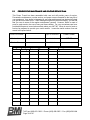
Revision Rev. Date Details Approved
0 01-31-2008 Initial document release G.M.T.
1 08-17-2009 Relocation D.M.
No part of this work may be reproduced or transmitted in any
form or by any means, electronic or mechanical, including
photocopying and recording, or by any information storage or
retrieval system without the prior written permission of Bartell
Morrison Inc. unless such copying is permitted by federal
copyright laws.
Address inquiries or reference permissions care of:
Bartell Morrison Inc., 375 Annagem Blvd., Mississauga,
Ontario, Canada, L5T 3A7

Toll Free: (866) 501-1683 / Phone: (905) 458-5455 / Fax: (905) 458-5484
Page 3 of 38
TABLE OF CONTENTS:
TABLE OF CONTENTS:TABLE OF CONTENTS:
TABLE OF CONTENTS:
PRODUCT SAFETY
PRODUCT SAFETYPRODUCT SAFETY
PRODUCT SAFETY
5
55
5
1.0 MEET THE NEXUS NXT
1.0 MEET THE NEXUS NXT1.0 MEET THE NEXUS NXT
1.0 MEET THE NEXUS NXT-
--
-90 POWER TROWEL
90 POWER TROWEL90 POWER TROWEL
90 POWER TROWEL
6
66
6
1.1 EQUIPMENT USE AND CARE 6
1.2 SAFETY FEATURES 6
1.3 NXT-90 DIMENSIONS 7
1.4 NXT-90 MAIN COMPONENTS 9
1.5 LIFTING THE NXT-90 11
2.0 SAFETY
2.0 SAFETY2.0 SAFETY
2.0 SAFETY
12
1212
12
2.1 SAFETY AND OPERATIONAL LABELS 14
2.2 DOUBLE-DEADMAN SAFETY HANDLE 17
3.0 SETTING UP THE NXT
3.0 SETTING UP THE NXT3.0 SETTING UP THE NXT
3.0 SETTING UP THE NXT-
--
-90
9090
90
18
1818
18
3.1 USING THE FOLDING HANDLE 18
3.2 STARTING THE NXT-90 21
4.0 TROWEL TECHNIQUE
4.0 TROWEL TECHNIQUE4.0 TROWEL TECHNIQUE
4.0 TROWEL TECHNIQUE
22
2222
22
4.1 TROWELLING 23
4.2 POWER TROWEL BLADES 25
4.3 FLOAT BLADES 26
4.4 FLOAT PANS 27
4.5 BLADE PITCH 28
5.0 STORAGE AND SERVICE
5.0 STORAGE AND SERVICE5.0 STORAGE AND SERVICE
5.0 STORAGE AND SERVICE
29
2929
29
5.1 PREVENTATIVE MAINTENANCE AND ROUTINE SERVICE 30
5.2 ROUTINE SERVICE INTERVALS 32
5.3 STORAGE 32
5.4 TROWEL ARM ADJUSTMENT 33
CE DECLARATION OF CONFORMITY
CE DECLARATION OF CONFORMITYCE DECLARATION OF CONFORMITY
CE DECLARATION OF CONFORMITY
36
3636
36
NOTES
NOTESNOTES
NOTES
38
3838
38
TABLE OF ILLUSTRATIONS & FIGURES
TABLE OF ILLUSTRATIONS & FIGURESTABLE OF ILLUSTRATIONS & FIGURES
TABLE OF ILLUSTRATIONS & FIGURES
FIGURE PG.
FIGURE PG.
FIGURE 1: FOLDED DIMENSIONS. . . . . . . 7
FIGURE 13: IDEAL TROWELLING MOTION.
23
FIGURE 2: OPERATING DIMENSIONS. . . .
8
FIGURE 14: TROWELLING PASS DIR. . . . . 24
FIGURE 3: MAJOR COMPONENTS. . . . . . .
9
FIGURE 15: TYPICAL FINISHING BLADE. . 25
FIGURE 4: PROPER LIFTING. . . . . . . . . . . 11
FIGURE 16: LOOSEN RETAINING BOLTS. .
25
FIGURE 5: LABEL LOCATIONS. . . . . . . . . .
14
FIGURE 17: ROTATE THE BLADE. . . . . . . . 26
FIGURE 6: DEADMAN HANDLE OPER. . . .
17
FIGURE 18: TYPICAL FLOAT BLADE. . . . . .
26
FIGURE 7: FOLDED HANDLE FEATURES. 18
FIGURE 19: TYPICAL FLOAT PAN. . . . . . . .
27
FIGURE 8: UNLOCKING THE BAR. . . . . . . 19
FIGURE 20: PITCHING THE BLADES. . . . . .
28
FIGURE 9: UNFOLDING THE HANDLE. . . .
20
FIGURE 21: TROWEL ARM LIFT ASSY. . . . 33
FIGURE 10: HANDLE LOCK KNOB. . . . . . .
20
FIGURE 22: ARM ADJUSTMENT FIXTURE. 33
FIGURE 11: PULL-STARTING THE NXT-90 21
FIGURE 23: SPIDER ASSY OIL BATH FILL. 34
FIGURE 12: STEERING THE NXT-90. . . . . 22

Toll Free: (866) 501-1683 / Phone: (905) 458-5455 / Fax: (905) 458-5484
Page 4 of 38
This page intentionally left blank

Toll Free: (866) 501-1683 / Phone: (905) 458-5455 / Fax: (905) 458-5484
Page 5 of 38
PRODUCT SAFETY
PRODUCT SAFETYPRODUCT SAFETY
PRODUCT SAFETY
READ OPERA
READ OPERAREAD OPERA
READ OPERATING INSTRUCTIONS
TING INSTRUCTIONSTING INSTRUCTIONS
TING INSTRUCTIONS
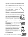
Read and understand this entire manual before attempting to
operate or service the equipment described herein. Failure to
follow these operating instructions could result in serious injury or
death. Store this manual with the machine and ensure it is
apparent and available to any users.
CALIFORNIA PROPOSITION 65 WARNING
CALIFORNIA PROPOSITION 65 WARNINGCALIFORNIA PROPOSITION 65 WARNING
CALIFORNIA PROPOSITION 65 WARNING
Engine exhaust, some of its constituents, and certain vehicle
components, contain or emit chemicals known to the State of
California to cause cancer and birth defects or other reproductive
harm.
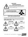
PRODUCT SAFETY AND HAZARD ALERT SYSTEM:
PRODUCT SAFETY AND HAZARD ALERT SYSTEM:PRODUCT SAFETY AND HAZARD ALERT SYSTEM:
PRODUCT SAFETY AND HAZARD ALERT SYSTEM:
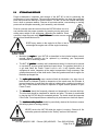
This Operating Manual presents Product Safety and Hazard Alert Information in
accordance with
American National Standards Institute
and
International Organization for
Standardization
recommendations as laid out in ANSI Z535 and ISO 3864. The callouts of
DANGER, WARNING, CAUTION, and NOTE must be followed to reduce or avoid the
potential for personal injury, equipment damage, or service-related equipment failures.
Safety Hazard Ale
Safety Hazard AleSafety Hazard Ale
Safety Hazard Alert:
rt:rt:
rt:
Alerts the reader to
personal injury hazards
and other important,
potentially life-saving
information.
DANGER:
DANGER:DANGER:
DANGER:
Beware of a hazardous
situation that WILL result in
serious personal injury or
death.
WARNING:
WARNING:WARNING:
WARNING:
Beware of a hazardous
situation that COULD
result in serious personal
injury or even death.
CAUTION:
CAUTION:CAUTION:
CAUTION:
Beware of a hazardous
situation that could result in
minor personal injury or
equipment damage.

Toll Free: (866) 501-1683 / Phone: (905) 458-5455 / Fax: (905) 458-5484
Page 6 of 38
1.0
1.01.0
1.0 MEET T
MEET TMEET T
MEET THE NEXUS
HE NEXUS HE NEXUS
HE NEXUS NXT
NXTNXT
NXT-
--
-90
9090
90 POWER TROWEL
POWER TROWEL POWER TROWEL
POWER TROWEL
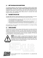
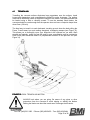
The equipment depicted in these instructions is a pedestrian controlled, gasoline engine
powered assembly including a rotor on which blades are attached that contact an uncured
concrete surface. The rotor turns around a central shaft when under power and is
supported through a worm gear speed reducer. For control of this assembly a handle is
provided for the operator to grasp and manipulate the travel of the machine on the
concrete surface. The assembly includes safety devices in accordance with North
American and International standards.
1.1
1.11.1
1.1
E
EE
EQUIPMENT
QUIPMENT QUIPMENT
QUIPMENT USE
USEUSE
USE AND CARE
AND CARE AND CARE
AND CARE
The Nexus NXT-90 Power Trowel is designed for use on uncured concrete. It should be
operated at all times in accordance with the instructions detailed in this manual:
• Use of this equipment for any purpose other than that stated within creates the risk
of personal injury and/or property damage.
• Any modifications to the equipment must be performed by the manufacturer or an
authorized dealer and must be authorized in advance by the manufacturer.
• The equipment should be serviced, cleaned, and stored as detailed by this manual.
The manufacturer of this equipment cannot be held responsible for any damages resulting
from misuse, abuse, or neglect.
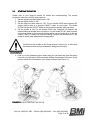
1.2
1.21.2
1.2
SAFETY FEATURES
SAFETY FEATURESSAFETY FEATURES
SAFETY FEATURES
The Nexus NXT-90 Power Trowel is equipped with safety guards in accordance with North
American and International standards. The main safety ring protects the blades from
collisions with solid objects, but more importantly protects the operator from the blades.
The belt guard protects the operator from the main drive belt. The handle is equipped with
a “double-deadman” operator presence system as standard equipment. The use and
function of this system is covered in the next section.
NEVER
NEVERNEVER
NEVER attempt to disable or circumvent these safety devices. They are
present for the operator’s protection and any tampering will result in
substantial risk to the operator and all present at the job site. If your NXT-
90 safety devices have been tampered with, do not use the Power Trowel.
Immediately contact your sales representative to obtain replacement parts
or return the trowel to your dealer for repairs.

Toll Free: (866) 501-1683 / Phone: (905) 458-5455 / Fax: (905) 458-5484
Page 7 of 38
1
11
1.
..
.3
33
3
NXT
NXTNXT
NXT-
--
-90
9090
90 DIMENSIONS
DIMENSIONS DIMENSIONS
DIMENSIONS
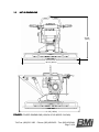
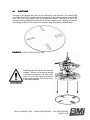
FIGURE 1:
FIGURE 1:FIGURE 1:
FIGURE 1: FOLDED DIMENSIONS (HONDA GC160 MODEL SHOWN)
38
-
3/4” (98cm)
27-5/8”
(70cm)
41
-
3/8” (105cm)

Toll Free: (866) 501-1683 / Phone: (905) 458-5455 / Fax: (905) 458-5484
Page 8 of 38
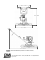
FIGURE 2:
FIGURE 2:FIGURE 2:
FIGURE 2: OPERATING DIMENSIONS (HONDA GC160 MODEL SHOWN)
28
-
1/8” (71.5cm)
38
-
3/4” (98cm)
37
-
1/2” (95cm)
64
-
3/8” (163.5cm)

Toll Free: (866) 501-1683 / Phone: (905) 458-5455 / Fax: (905) 458-5484
Page 9 of 38
1.4
1.41.4
1.4
NXT
NXTNXT
NXT-
--
-90 MAIN COMPONENTS
90 MAIN COMPONENTS90 MAIN COMPONENTS
90 MAIN COMPONENTS
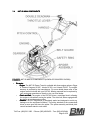
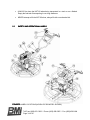
FIGURE 3:
FIGURE 3:FIGURE 3:
FIGURE 3: NXT-90 MAJOR COMPONENTS (HONDA GC160 MODEL SHOWN)
• Drivetrain:
Drivetrain:Drivetrain:
Drivetrain:
o Engine:
Engine:Engine:
Engine: The NXT-90 Power Trowel is available with three engine options:
Briggs
& Stratton
Vanguard 6.5HP,
Honda
GC160, and
Honda
GX160. The engine
warranty is provided by the manufacturer. For more details please refer to the
engine manual included with your NXT-90. Missing manuals can be replaced by
your equipment manufacturer directly or via your local dealer.
o Clutch and Belt:
Clutch and Belt:Clutch and Belt:
Clutch and Belt: The engine of the NXT-90 drives a centrifugal clutch, allowing
the engine to idle without turning the spider. The drive belt, when engaged with
the clutch, drives the gearbox pulley.
o Gearbox:
Gearbox:Gearbox:
Gearbox: The NXT-90 gearbox is completely sealed and designed to avoid any
leakage over the equipment’s lifetime. The pulley attached to the countershaft
drives a worm gear that turns the spider. The spider assembly and blade pitch
control hardware attach to main shaft.

Toll Free: (866) 501-1683 / Phone: (905) 458-5455 / Fax: (905) 458-5484
Page 10 of 38
• Be
BeBe
Belt Guard:
lt Guard:lt Guard:
lt Guard: Designed to protect the operator from the rotating components of the
drivetrain, the belt guard mounts directly to the engine and should never be removed
during operation.
• Safety Ring:
Safety Ring:Safety Ring:
Safety Ring: Serves the dual purpose of protecting the rotating spider assembly from
impacts with obstacles, and keeps the operator’s hands and feet out of the path of
the blades. The safety ring is removable for easier blade maintenance, and is
mounted with rubber shock absorbers to reduce vibration and noise. The safety ring
should always be installed before starting the engine.
• Spider:
Spider: Spider:
Spider: The spider assembly consists of the spider hub and trowel arms, the trowel
blades, the blade pitch arms, and the stabilizer ring. The entire assembly is attached
to the main gearbox shaft via a single bolt and square key. The trowel blades are
double-edged for extra life and designed for easy replacement. A bent trowel arm will
severely affect the performance of your Power Trowel, so these can easily be
replaced.
• Handle:
Handle:Handle:
Handle: When unfolded and locked, the handle provides the operator with easy and
ergonomic control over the Power Trowel. When folded over and locked in place, the
handle becomes a hoist lift point and a protective cage for the engine during
transportation. Please refer to the
Trowel Technique
section for details on how to
properly use the NXT-90.
• Throttle Lever:
Throttle Lever:Throttle Lever:
Throttle Lever: The throttle lever provides the operator with quick and reliable control
of the engine speed. The lever will move in different directions for different engine
configurations. On the
Honda
GC160 model of NXT-90, setting the throttle lever to
minimum will shut down the engine, while the other models will simply set the Power
Trowel to idle.
• Double Deadman System:
Double Deadman System:Double Deadman System:
Double Deadman System: Designed to protect the operator and equipment in the
event the operator lets go with both hands, the engine will immediately shut down. By
using two deadman handles, the operator can release either hand while holding on
with the other without shutting down the engine. When released, the trowel will begin
to spin freely, but with the engine shut down, even from full speed, the trowel will
come to a full stop within ½ rotation. Please refer to the
Safety
section for further
details.

Toll Free: (866) 501-1683 / Phone: (905) 458-5455 / Fax: (905) 458-5484
Page 11 of 38
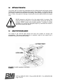
1.5
1.51.5
1.5
LIFTING THE NXT
LIFTING THE NXTLIFTING THE NXT
LIFTING THE NXT-
--
-90
9090
90
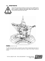
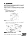
The NXT-90 should always be lifted by mechanical means. NEVER attempt
to lift it by yourself, as this can result in back strain and other injuries, as
well as damage to equipment and property. Ensure the engine is not
running and has cooled down before lifting.
FIGURE 4:
FIGURE 4:FIGURE 4:
FIGURE 4: PROPER LIFTING
The NXT-90 should be lifted by mechanical means. With the handle folded and locked in
position the lift point can be used with a grab hook or sling to lift the Power Trowel into
position.

Toll Free: (866) 501-1683 / Phone: (905) 458-5455 / Fax: (905) 458-5484
Page 12 of 38
2.0
2.02.0
2.0
SAFETY
SAFETYSAFETY
SAFETY
The instructions provided in this manual are done so to ensure the
operator’s safety as well as that of others, the equipment, and the job site.
Failure to abide by these guidelines can lead to serious personal injury and
even death. The operator and any service personnel should read and
understand the entire manual before working with or servicing the NXT-90.
• The NXT-90 manual should be kept at all times in a place that
is accessible to any persons working with the machine.
Replacement manuals can be purchased from the equipment
manufacturer or from your local dealer.
• Only use parts and attachments supplied or approved by your Nexus equipment
manufacturer. The consequences of modifying the design of this equipment can
include personal injury, equipment failure, and voiding your warranty. If you are
unsure about a repair or an apparent malfunction, contact your Nexus dealer or the
phone contacts at the bottom of each page of this manual.
• Technical service bulletins, user’s manual updates, and other
information are posted on the Nexus website: .
http://www.nexusequip.com
http://www.nexusequip.comhttp://www.nexusequip.com
http://www.nexusequip.com
Check this website periodically for updates or other potentially
useful information about your equipment.
• NEVER use the NXT-90 in an enclosed space with poor air
flow, such as a basement or small room. The gasoline engine
produces, among other things, toxic carbon monoxide gas.
Without proper ventilation, this gas will build up and cause
health effects such as organ damage and death to anyone in
the vicinity.
• The Power Trowel operator should always be lucid and aware of his/her
surroundings. NEVER operate the NXT-90 while under the influence of drugs,
alcohol, fatigue, sickness, hangover, extreme depression, emotional distraction, or
medications/substances that may affect motor skills or judgment.
• ALWAYS wear the appropriate personal protective equipment
(PPE) while operating the NXT-90 Power Trowel. This
includes (but is not limited to) safety glasses, hearing
protection, protective footwear, and heavy or padded gloves.
Other safety gear may be job-site appropriate.
• NEVER leave the NXT-90 unattended while running.

Toll Free: (866) 501-1683 / Phone: (905) 458-5455 / Fax: (905) 458-5484
Page 13 of 38
• ALWAYS ensure that the operators have been properly trained prior to using the
equipment.
• Children and small animals should NEVER be present in the work area during
operation of the NXT-90.
• ALWAYS check your NXT-90 for loose or missing nuts and
bolts before starting. Tighten any loose fasteners and replace
missing or broken parts.
• Perform all routine maintenance as described within this
manual. Failure to do so will void your warranty and will
eventually result in premature equipment failure.
• NEVER perform maintenance on a running piece of equipment. Shut down the
engine and allow it to cool before servicing the NXT-90, including mechanical work
or lubrication.
• ALWAYS replace missing, damaged or unclear safety labels to ensure operator
awareness and safety.
• NEVER operate the NXT-90 with missing or damaged safety
guards. Replace immediately with appropriate Nexus parts.
• NEVER put hands, feet, or other appendages inside the guard
ring or belt guard while the engine is running, even at idle or
with protective clothing, as serious injury may result.
• NEVER wear loose fitting clothing or jewellery around rotating equipment such as
the NXT-90 as it may become entangled in the machinery, resulting in serious
injury.
• NEVER fuel the NXT-90 while the engine is running. Ensure
the engine has cooled sufficiently before refueling to avoid
igniting gasoline fumes.
• ALWAYS refuel the NXT-90 in a well-ventilated area, away
from ignition sources such as sparks, flames, and lit cigarettes.
Smoking while fuelling the equipment may result in explosion.
• NEVER operate the NXT-90 in explosive environments such
as those where paint fumes, methane, natural gas, fine
particulate, aerosol propellant, or solvent fumes are present.
• NEVER smoke near the NXT-90 as stray gasoline fumes may
ignite. Operating the NXT-90 around an open flame may also
result in explosion.
• ALWAYS shut down the engine and allow it to cool off before
lifting or transporting the NXT-90.

Toll Free: (866) 501-1683 / Phone: (905) 458-5455 / Fax: (905) 458-5484
Page 14 of 38
• ALWAYS tie down the NXT-90 when being transported in a truck or on a flatbed.
Empty the fuel tank if transporting it over long distances.
• NEVER attempt to lift the NXT-90 alone, always lift with a mechanical aid.
2.1
2.12.1
2.1
SAFETY AND OPERATIONAL LABELS
SAFETY AND OPERATIONAL LABELSSAFETY AND OPERATIONAL LABELS
SAFETY AND OPERATIONAL LABELS
FIGURE 5:
FIGURE 5:FIGURE 5:
FIGURE 5: LABEL LOCATIONS (HONDA GC160 MODEL SHOWN)

Toll Free: (866) 501-1683 / Phone: (905) 458-5455 / Fax: (905) 458-5484
Page 15 of 38
1 & 2
1 & 21 & 2
1 & 2
Nexus Product Brand Labels
3
33
3
Nexus Model and Serial Number plate (2
locations)
4
44
4
Product Model Number
NXT-90
5
55
5
WARNING: Use appropriate protective
clothing, including hearing protection,
shatter-resistant eyewear, steel toed boots,
and protective handwear
6
66
6
WARNING: Keep hands and feet clear of
rotating blades
7
77
7
DANGER: Keep hands clear of drive belt
while engine running
8
88
8
Throttle control lever movement: Stop,
Slow, Fast
9
99
9
WARNING: Hot surface, do not touch

Toll Free: (866) 501-1683 / Phone: (905) 458-5455 / Fax: (905) 458-5484
Page 16 of 38
10
1010
10
DANGER: Exhaust products can be toxic,
use in well-ventilated environment
11
1111
11
CAUTION: Mechanical lift point; hoist by
this point only
12
1212
12
Maximum sound level 105dB
13
1313
13
WARNING: Shut down engine and allow
sufficient cooling time before refueling this
equipment
14
1414
14
CAUTION: Read and understand entire
operator’s manual before using or servicing
this equipment

Toll Free: (866) 501-1683 / Phone: (905) 458-5455 / Fax: (905) 458-5484
Page 17 of 38
2.2
2.22.2
2.2
DOUBLE
DOUBLEDOUBLE
DOUBLE-
--
-DE
DEDE
DEADMAN SAFETY HANDLE
ADMAN SAFETY HANDLEADMAN SAFETY HANDLE
ADMAN SAFETY HANDLE
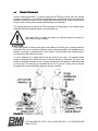
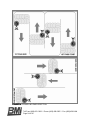
The Nexus NXT-90 comes equipped with an operator presence system that allows the
user to run the Power Trowel with the freedom to take either hand off of the handle without
shutting down the engine. If both hands are removed for any reason, such as a fall,
stumble, or other emergency, the engine will shut down to prevent runaway equipment.
ENGINE RUN
ENGINE RUN ENGINE RUN
ENGINE RUN
ENGINE RUN
ENGINE RUNENGINE RUN
ENGINE RUN
ENGINE STOP!
ENGINE STOP!ENGINE STOP!
ENGINE STOP!
FIGURE 6:
FIGURE 6:FIGURE 6:
FIGURE 6: DEADMAN HANDLE OPERATION
It should be noted that the NXT-90 will immediately begin to rotate in the
opposite direction to the blades when both of the handles are released.
Even with the engine shut down, the drivetrain will have sufficient
momentum to spin the handle up to 180
O
(1/2 turn) before coming to a stop.
For this reason, do not attempt to grab the handle after releasing it. Stand
clear and let the equipment come to rest before approaching it again.

Toll Free: (866) 501-1683 / Phone: (905) 458-5455 / Fax: (905) 458-5484
Page 18 of 38
3.0
3.03.0
3.0
SETTING UP THE NXT
SETTING UP THE NXTSETTING UP THE NXT
SETTING UP THE NXT-
--
-90
9090
90
Your Nexus NXT-90 comes fully assembled with the folding handle and engine already
installed. Nexus equipment is shipped without engine oil or gasoline, so fill these fluids per
your engine’s instruction manual before proceeding. When starting an engine for the first
time, or after a long period of storage, several pulls may be required before the engine
runs.
NEVER attempt to add fuel or oil to the engine while it is running. Shut
down the engine and allow it to cool down before opening the fuel cap for
refueling. NEVER smoke while handling gasoline. If gasoline is spilled
anywhere on or around the equipment wipe it up and allow the fumes to
clear before starting the engine.
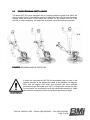
3.1
3.13.1
3.1
USING THE FOLDING HANDLE
USING THE FOLDING HANDLE USING THE FOLDING HANDLE
USING THE FOLDING HANDLE
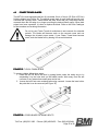
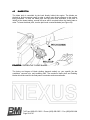
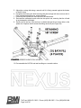
The handle of the NXT-90 folds forward and locks into position for storage and
transportation. The upper handle becomes a protective cage for the engine and a
balanced hoist point for mechanical lifting.
FIGURE 7:
FIGURE 7:FIGURE 7:
FIGURE 7: FOLDED HANDLE FEATURES

Toll Free: (866) 501-1683 / Phone: (905) 458-5455 / Fax: (905) 458-5484
Page 19 of 38
ALWAYS unfold the handle and lock in the open position before starting the
engine. Failure to do this may result in equipment damage or personal
injury.
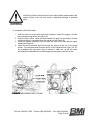
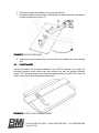
To completely unfold the handle:
1. Grab the lock arm at the hook and push backward, toward the engine, until the
latch releases the grab bar (see Figure 8).
2. Once the latch is free, lower the hook beneath the grab bar and bring it forward
until the lock arm is completely free of the grab bar (see Figure 8).
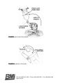
3. Unfold the handle completely. Fold the lock arm down to be flush with the upper
handle (see Figure 9).
4. Insert the lock screw with hand knob (near the joint) into the nut on the lower
handle. Turn the hand knob clockwise until it is fully tightened (see Figure 10). Do
not overtighten the hand knob using a wrench or other tool, as this will make
unlocking the handle difficult and risks stripping the threads on the lock screw.
FIGURE 8:
FIGURE 8:FIGURE 8:
FIGURE 8: UNLOCKING THE LOCK BAR

Toll Free: (866) 501-1683 / Phone: (905) 458-5455 / Fax: (905) 458-5484
Page 20 of 38
FIGURE 9:
FIGURE 9:FIGURE 9:
FIGURE 9: UNFOLDING THE HANDLE
FIGURE 10:
FIGURE 10:FIGURE 10:
FIGURE 10: HANDLE LOCK KNOB
La pagina si sta caricando...
La pagina si sta caricando...
La pagina si sta caricando...
La pagina si sta caricando...
La pagina si sta caricando...
La pagina si sta caricando...
La pagina si sta caricando...
La pagina si sta caricando...
La pagina si sta caricando...
La pagina si sta caricando...
La pagina si sta caricando...
La pagina si sta caricando...
La pagina si sta caricando...
La pagina si sta caricando...
La pagina si sta caricando...
La pagina si sta caricando...
La pagina si sta caricando...
La pagina si sta caricando...
-
 1
1
-
 2
2
-
 3
3
-
 4
4
-
 5
5
-
 6
6
-
 7
7
-
 8
8
-
 9
9
-
 10
10
-
 11
11
-
 12
12
-
 13
13
-
 14
14
-
 15
15
-
 16
16
-
 17
17
-
 18
18
-
 19
19
-
 20
20
-
 21
21
-
 22
22
-
 23
23
-
 24
24
-
 25
25
-
 26
26
-
 27
27
-
 28
28
-
 29
29
-
 30
30
-
 31
31
-
 32
32
-
 33
33
-
 34
34
-
 35
35
-
 36
36
-
 37
37
-
 38
38


in altre lingue
- English: Nexus NXT-90 User manual
Altri documenti
-
 Bartell B446 Manuale del proprietario
-
 Stafor S25BR4S25HR18S25KR6 Manuale del proprietario
-
Furuno DRS4DNXT Guida d'installazione
-
Pioneer S-FL1 Manuale utente
-
Peerless ACC-DHP6 Manuale utente
-
Klipsch KG 3 Manuale del proprietario
-
Edgewater Networks 240IS Manuale del proprietario
-
Yamaha RX21 Manuale del proprietario
-
-
JVC SP-AP300 Manuale utente

