HK Audio LINEAR 7 112 XA Manuale utente
- Categoria
- Altoparlanti della soundbar
- Tipo
- Manuale utente

Manual 1.2
• English • Français• Deutsch • Italiano • Español
LINEAR 7
LINEAR 7 110 XA • LINEAR 7 112 XA
LINEAR 7 112 FA • LINEAR 7 115 FA
LINEAR 7 118 Sub A

Important Safety Instructions!
Read before connecting!
This product has been built by the manufacturer in accordance with
IEC 62368-1 and left the factory in safe working order. To maintain
this condition and ensure non-risk operation, the user must follow the
advice and warning comments found in the operating instructions. If
this product shall be used in vehicles, ships or aircraft or at altitudes
exceeding 2000 m above sea level, take care of the relevant safety
regulations which may exceed the IEC 62368-1 requirements.
WARNING: To prevent the risk of fire and shock hazard, do not
expose this appliance to moisture or rain. Do not open case – no user
serviceable parts inside. Refer service to qualified service personnel.
This symbol, wherever it appears, alerts you to the presence
of uninsulated dangerous voltage inside the enclosure – voltage that
may be sufficient to constitute a risk of shock.
This symbol, wherever it appears, alerts you to the presence
of externally accessible hazardous voltage. External wiring connected
to any terminal marked with this symbol must be a “ready made
cable” complying with the manufacturers recommendations, or must
be a wiring installed by instructed persons only.
This symbol, wherever it appears, alerts you to important
operating and maintenance instructions in the accompanying
literature. Read the manual.
This symbol, wherever it appears, tells you: Take care! Hot
surface! To prevent burns you must not touch.
All electrical and electronic products including batteries
should be disposed of separately from the municipal waste stream via
designated collection facilities appointed by the government or the
local authorities.
Read these instructions. Keep these instructions. Follow all
warnings and instructions marked on the product and in this manual.
• Do not use this product near water. Do not place the product near
water, baths, wash basins, kitchen sinks, wet areas, swimming pools
or damp rooms.
• Do not place objects containing liquid on the product – vases,
glasses, bottles etc.
• Clean only with dry cloth.
• Do not remove any covers or sections of the housing.
• The set operating voltage of the product must match the local mains
supply voltage. If you are not sure of the type of power available
consult your dealer or local power company.
• Before connecting the device, please ensure that the mains supply
you are using is equipped with adequate protection against short
circuiting and grounding faults when the device is plugged in.
• To reduce the risk of electrical shock, the grounding of this product
must be maintained. Use only the power supply cord provided with
this product, and maintain the function of the center (grounding)
pin of the mains connection at any time. Make sure the mains outlet
used provides a proper protective ground connection.
• Do not defeat the safety purpose of the polarized or grounding-type
plug. A polarized plug has two blades with one wider than the other.
A grounding type plug has two blades and a third grounding prong.
The wide blade or the third prong are provided for your safety. If the
provided plug does not fit into your outlet, consult an electrician for
replacement of the obsolete outlet.
• Protect the power cord from being walked on or pinched particularly
at plugs, convenience receptacles, and the point where they exit
from the device! Power supply cords should always be handled
carefully. Periodically check cords for cuts or sign of stress, especially
at the plug and the point where the cord exits the device.
• Never use a damaged power cord.
• Unplug this product during lightning storms or when unused for long
periods of time.
• This product can be fully disconnected from mains only by pulling
the mains plug at the unit or the wall socket. The product must be
placed in such a way at any time, that disconnecting from mains is
easily possible.
• Fuses are to be replaced exclusively by qualified personnel, and then
only with fuses of the proper type and rating.
• Refer all servicing to qualified service personnel. Servicing is
required when the unit has been damaged in any way, such as:
- When the power cord or plug is damaged or frayed.
- If liquid has been spilled or objects have fallen into the product.
- If the product has been exposed to rain or moisture.
- If the product does not operate normally when the operating
instructions are followed.
- If the product has been dropped or the cabinet has been damaged.
• Do not connect external speakers to this product with an impedance
lower than the rated impedance given on the product or in this
manual. Use only cables with sufficient cross section according to
the local safety regulations.
• Keep away from direct sunlight.
• Do not install near heat sources such as radiators, heat registers,
stoves or other devices that produce heat.
• This apparatus is for moderate climates areas use, not suitable for
use in tropical climates countries.
• Do not block any ventilation openings. Install in accordance with
manufacturer’s instructions. This product must not be placed in
a built-in installation such as a rack unless proper ventilation is
provided.
• Always allow a cold device to warm up to ambient temperature,
when being moved into a room. Condensation can form inside it and
damage the product, when being used without warming up.
• Do not place naked flame sources, such as lighted candles on the
product.
• The device must be positioned at least 20 cm/8" away from walls.
• Use only with the cart, stand, tripod, bracket or table specified by
the manufacturer or sold with the product. When a cart is used, use
caution when moving the cart/product combination to avoid injury
from tip-over.
• Use only accessories recommended by the manufacturer, this applies
for all kind of accessories, for example protective covers, transport
bags, stands, wall or ceiling mounting equipment. In case of
attaching any kind of accessories to the product, always follow the
instructions for use, provided by the manufacturer. Never use fixing
points on the product other than specified by the manufacturer.
• This appliance is NOT suitable to be used by any person or persons
(including children) with limited physical, sensorical or mental
ability, or by persons with insufficient experience and/or knowledge
to operate such an appliance. Children under 4 years of age must be
kept away from this appliance at all times.
• Never push objects of any kind into this product through cabinet
slots as they may touch dangerous voltage points or short out parts
that could result in risk of fire or electric shock.
• This product is capable of delivering sound pressure levels in excess
of 90 dB, which may cause permanent hearing damage! Exposure
to extremely high noise levels may cause a permanent hearing loss.
Wear hearing protection if continously exposed to such high levels.
• The manufacturer only guarantees the safety, reliability and
efficiency of this product if:
- Assembly, extension, re-adjustment, modifications or repairs are
carried out by the manufacturer or by persons authorized to do so.
- The electrical installation of the relevant area complies with the
requirements of IEC (ANSI) specifications.
- The unit is used in accordance with the operating instructions.
• This product is optimized for use with music and speech signals.
Using this product with sine wave, square wave or other kind of
measuring signals at higher level may lead to severe damage of the
product.
General Notes on Safety for Loudspeaker
Systems
Mounting systems may only be used for those loudspeaker
systems authorized by the manufacturer and only with the mounting
accessories specified by the manufacturer in the installation
instructions. Read and heed the manufacturer’s installation
instructions. The indicated load-bearing capacity cannot be guaranteed
and the manufacturer will not be liable for damages in the event of
improper installation or the use of unauthorized mounting accessories.
The system’s load-bearing capacity cannot be guaranteed and
the manufacturer will not be liable for damages in the event that
loudspeakers, mounting accessories, and connecting and attaching
components are modified in any way.
Components affecting safety may only be repaired by the manufacturer
or authorized agents, otherwise the operating permit will be voided.
Installation may be performed qualified personnel only, and
then only at pick-points with sufficient load-carrying capacity and
in compliance with local building regulations. Use only the mounting
hardware specified by the manufacturer in the installation instructions
(screws, anchors, etc.). Take all the precautions necessary to ensure
bolted connections and other threaded locking devices will not loosen.
Fixed and portable installations (in this case, speakers and
mounting accessories) must be secured by two independent safeties to
prevent them from falling. Safeties must be able to catch accessories
or parts that are loose or may become loose. Ensure compliance with
the given national regulations when using connecting, attaching,
and rigging devices. Factor potential dynamic forces (jerk) into the
equation when determining the proper size and load-bearing capacity
of safeties.
Be sure to observe speaker stands’ maximum load-bearing
capacity. Note that for reasons of design and construction, most
speaker stands are approved to bear centric loads only; that is, the
speakers’ mass has to be precisely centered and balanced. Ensure
speaker stands are set up stably and securely. Take appropriate added
measures to secure speaker stands, for example when:
- the floor or ground surface does not provide a stable, secure base.
- they are extended to heights that impede stability.
- high wind pressure may be expected.
- there is the risk that they may be knocked over by people.
Special measures may become necessary as precautions against
unsafe audience behavior. Do not set up speaker stands in evacuation
routes and emergency exits. Ensure corridors are wide enough and put
proper barriers and markings in place when setting speaker stands up
in passageways. Mounting and dismounting are especially hazardous
tasks. Use aids suitable for this purpose. Observe the given national
regulations when doing so.
Wear proper protection (in particular, a helmet,
gloves, and safety shoes) and use only suitable means of ascent
(ladders, scaffolds, etc.) during installation. Compliance with this
requirement is the sole responsibility of the company performing the
installation.
WARNING! After installation, inspect the system comprised
of the mounting fixtures and loudspeakers to ensure it is properly
secured.
The operator of loudspeaker systems (fixed or portable) must
regularly inspect or task a third party to regularly inspect all system
components in accordance with the given country’s regulations and
have possible defects repaired immediately.
We also strongly recommend maintaining a logbook or the like to
document all inspections.
Also be sure to provide sufficient safety margins for the rigging points
used for flown systems. Observe the given national regulations when
doing so.
Professional loudspeaker systems can produce harmful
volume levels. Even prolonged exposure to seemingly harmless levels
(starting at about 95 dBA SPL) can cause permanent hearing damage!
Therefore we recommend that everyone who is exposed to high volume
levels produced by loudspeaker systems wears professional hearing
protection (earplugs or earmuffs).
Manufacturer: Stamer Musikanlagen GmbH, Magdeburger Str. 8, 66606
St. Wendel, Germany
Version 2.8 08/2019

LINEAR 7 1.2
3
Welcome to the HK Audio family!
Thank you for choosing a brand-name product made by our company. Rest
assured, we engineered and built it with the greatest care so it will serve
you well for many tomorrows to come.
Even if your experience with sound systems runs deep, some things
about this product are sure to be new to you. This is why we ask that you do
not set this manual aside without reading it fi rst. Be sure to keep it in a
safe place for later reference.
Here's wishing you the best sound at every occasion!
Your HK Audio team
Strong electromagnetic interference or electrostatic discharge
may prevent the product from functioning normally. If this happens, the
product may be returned to normal operation by powering o and on
again. Should this not result in the product functioning normally again,
please move the product away from the source of disturbance and try
again.
Warranty
Use the convenient online registration option at www.hkaudio.com.
http://warranty.hkaudio.com
The registration is only valid if the device is registered within 30 days of
the date of purchase.
HK Audio
Technischer Service
Postfach 1509
66595 St. Wendel, Germany
Fax: +49 6851 905 100
• English • Français• Deutsch • Italiano • Español
LINEAR 7
L7 110 XA L7 112 FA L7 112 XA L7 115 FA L7 118 Sub A

LINEAR 7 1.2
4
1 General Information
Unpacking and Inventorying
When you fi rst unpack your LINEAR 7 speaker cabinet, take a quick
inventory to make sure it comes complete with the manual and Powercon
mains cable.
2 Connectors and Controls
+6 dB
0 dB
Input
DSP Out
Thru Gain
1
5
2 3
4
L7 XA/FA models
+6 dB–6 dB
0 dB
Input
L
R
DSP Out
Thru Gain
1
5
2
1 2
3
4
4
L7 118 Sub A
●
1 Input
This XLR/ 1/4" (6.35 mm) combo jack provides a balanced input for analog
signals.
• L7 XA/FA models have one input channel.
• The L7 118 Sub A subwoofer has two separate inputs for the left and right
signals. The two channels are equal and merged post-preamp, so you can
use either one in mono mode.
●
2 Thru
Use this parallel, balanced XLR output to send the signal routed into the
Input through to other components. This output remains active even when
the electronic components are deactivated. The subwoofer has two of these
ports.
●
3 Gain
Use this knob to adjust the input gain for the incoming signal.
• The control range for the XA/FA models sweeps from –∞ (mute) to +6 dB.
• This knob adjusts the gain for both of the L7 118 Sub A's stereo preamp
channels in a range of -6 to +6 dB.
The center-notched 12 o'clock position is 0 dB in both cases.
Heads up: The Gain setting does not a ect the signal sent to the DSP
Out.
●
4 Input/Limiter LED
This LED lights up green to indicate incoming signals and red to indicate
signal peaks. The LED briefl y fl ashes red to tell you the Limiter is
responding to signal peaks. If it stays red, turn down the Gain knob.
●
5 DSP Out
Use this XLR port to forward the signal routed into the Input jack or to
forward a digital audio signal streamed* in via Milan™, an AVB-based digital
audio network protocol. The onboard DSP can process both types of signals.
This means the DSP Out can serve as a network interface that lets you
integrate an added powered speaker that is not equipped with Ethernet
ports. You can even use it as an audio interface to send audio signals
streamed* in to the LINEAR 7 speaker on to other speakers, for example, to
powered LINEAR SUB series subwoofers.
In the factory default confi guration, the unprocessed input signal goes
straight to DSP Out it, regardless of the selected preset and the Gain knob
setting.
Power
Auto Sleep
On Off
Data
Flat
Low Cut
Remote
Preset
1
2
3
4
Thru
In
Ethernet
Boost
6
7
8
●
6 Ethernet In /Thru
Use the two Ethercon ports to integrate the speaker into a network. They
accept RJ45 and Ethercon (NE8 MX, NE8 MX6, NE8 MC) plugs. Use the
Ethernet Thru port to forward the network signal.
Always use S/STP or S/FTP cables to shield against electromagnetic
interference. We recommend CAT6 cables. A separate manual explains the
fi ner points of network integration, remote control functions and audio
streaming*.
You will fi nd it on the LINEAR 7 download page at www.hkaudio.com. For a
brief description of the DSP functions, see section ●
8 Preset.
●
7 Data
This LED lights up orange when data fl ows through the network connector.
*MILAN™ implementation/certifi cation was in the works at the time of writing. Visit www.hkaudio.com to get an update.

LINEAR 7 1.2
5
●
8 Preset
Use the Preset selection button to call up factory presets or a user preset
you can confi gure via the remote DSP CONTROL software. Tap the select
button once to scroll through Presets 1 through 4.
A separate manual explains how to program the four remote user presets.
You will fi nd it on the LINEAR 7 download page at www.hkaudio.com.
Presets:
L7 110 XA L7 112 XA L7 112 FA L7 115 FA L7 118 Sub A
1Flat Flat Flat Flat Front
2Monitor Monitor Boost Boost Cardioid 1
3Low Cut Low Cut Low Cut Low Cut Cardioid 2
4Remote (to access stored settings via the remote
HK Audio DSP CONTROL software)
The L7 XA/FA models' factory presets:
Flat Delivers linear response across the full frequency range
Monitor Optimized to dampen the extra bass generated by fl oor
coupling when you set a speaker on its side for use as a
monitor
Boost Enhances low-frequency response when you use the mid/
high unit a standalone speaker without a subwoofer
Low Cut A high-pass fi lter optimizes the unit for use as a mid/high
unit paired with the L7 118 Sub A
The L7 118 Sub A's factory presets:
Front Standard operating mode for a forward-facing subwoofer
Cardioid 1:1 For cardioid setups with one forward-facing L7 118 Sub A;
see section 4.2 for more on this
Cardioid 2:1 For cardioid setups with two forward-facing L7 118 Sub A;
see section 4.2 for more on this
Factory presets 1 to 3 address the speaker only and not the DSP Out.
Heads up: If you are operating the speaker in a network connected to
the remote DSP CONTROL software, you can confi gure the DSP Out
independently even when using factory presets 1 to 3. To learn more
about this, consult the separate DSP CONTROL manual. You will fi nd it
on the LINEAR 7 download page at www.hkaudio.com.
The Remote Preset
Remote This lets you call up a user preset that you previously stored
via DSP CONTROL for the speaker as well as for the DSP
Out. The speakers does not need to be connected to the
remote software to do this.
The remote preset's default setup is identical to factory preset 1 (Flat/
Front).
You can access the following DSP functions via the remote DSP CONTROL
software and save your settings in user presets:
Fully parametric 10-band EQ with variable fi lter characteristics for each
frequency band, high-pass and low-pass fi lters with variable fi lter
characteristics, Limiter, Delay, Polarity, Level, and Mute
You can confi gure these parameters separately and independently for the
speaker and its DSP Out.
Screenshot of the remote DSP CONTROL software. You can download this software free of charge at the
LINEAR 7 product page at www.hkaudio.com. The speaker and DSP Out parameters are identical, but
the powerful onboard DSP lets you configure each set independently.
●
9 Power
This rocker switch turns the power on and o . Set it to Power to turn the
electronic components on and to O to disconnect them from the mains
power supply. The Power switch does not a ect the Powercon Link port.
See section ●
12 below for more on this.
●
10 Power-LED
This LED lights up green when the electronic
components are getting mains power.
●
11 Mains Input
Use the factory-included Powercon mains cord
to connect this socket to a power outlet. Insert
the push-pull connector and turn it clockwise to
make sure the Powercon cord engages and locks.
To unlock it, pull the Powercon plug's locking
mechanism towards the cable and turn it counterclockwise.
Mains Input
100-240 V~ 50-60 Hz
1.9 A @ 1/8 output power
Link
100-240 V~ 50-60 Hz
max. 10 A
Power
Lock Lock
9
11 12
●
12 Link (L7 118 Sub A only)
This socket can power up to three additional LINEAR 7
speaker cabinets. Hardwired to the Mains Input, it is not
a ected by the Power switch setting. The Link circuit
goes live the moment you connect the Mains Input to
a power source. This is why you must make sure all
downstream devices are switched o before you connect
them to the Link port.
• English • Français• Deutsch • Italiano • Español
Power
Auto Sleep
On Off
10
13

LINEAR 7 1.2
6
●
13 Auto Sleep
Use this recessed button to switch energy-saving Auto Sleep mode on and
o . Your speaker leaves the factory with the Auto Sleep button pressed to
enable this mode. This function puts the electronic components to sleep
when four and a half hours pass without the speaker registering an audio
signal, data sent to the Ethercon ports, or an adjustment of a button or
knob. The only way to wake it up is by switching the Power button o and
on again or patching an analog audio signal into the Input.
Heads up: You cannot wake up the speaker via the Ethercon ports.
There is but one way to deactivate the Auto Sleep function – by
‘unpressing' the button to set it to the up position.
3 An Overview of the Various LINEAR 7
Models
L7 110 XA L7 112 FA L7 112 XA L7 115 FA L7 118 Sub A
The LINEAR 7 series consists of four mid/high units and a subwoofer, the
L7 110 XA, L7 112 XA, L7 112 FA, L7 115 FA and the L7 118 Sub A. The housings
of the multifunctional L7 110 XA and L7 112 XA models are angled 30° so you
can also set them sideways for use monitors. The larger housings of the
L7 112 FA and L7 115 FA fullrange models deliver more low-frequency sound
pressure.
30°
L7 110 XA / L7 112 XA
All XA and FA models are loaded with rotatable horns. The directivity of
each cabinet's horn is optimized for its primary purpose – that is, the most
frequently used application. The L7 110 XA cab sports a 10" woofer and
a horn with a wide 80°x60° throw pattern to provide uniform near-fi eld
coverage. L7 112 XA/FA cabs feature a 12" woofer and a horn with a medium
70°x50° throw pattern. The L7 115 FA cab comes with 15" woofer and a horn
with a narrow 60°x40° long-throw pattern.
You need tools to rotate the horns, so they are not conducive to frequent
adjustment. The idea is to optimize the throw pattern for the cabinet's
primary application.
Tip: You do not have to rotate the horn when setting the cab on its side
for use as a stage monitor. In fact, the upright speaker's narrower vertical
throw pattern works great in the horizontal position. Its tightly focused
directivity minimizes overlap with adjacent monitors and reduces the risk
of feedback risk because you can aim the speaker more accurately.
4 Setting Up Speakers
4.1 The XA/FA Models
LINEAR 7 mid/high units may be stacked on subwoofers, mounted on
speaker stands or poles, installed with wall brackets, or fl own with the
proper rigging hardware.
Setting Up with the DuoTilt 3/7
-3° -7°
All mid/high units feature the HK Audio DuoTilt 3/7, a special mount for 35
mm speaker stands and poles o ering two angles, -3° and -7°, to provide
better coverage. The DuoTilt 3/7 is sited closer to the ba e to maintain the
optimum center of gravity when the speaker is on a stand.
Setting Up with the Tilt Unit
-3° -7°
Tilt-Unit
HK Audio o ers an optional Tilt Unit if you wish to tilt the mid/high
units when they are stacked directly on subwoofers. It screws into the
subwoofer's M20 mount just like a speaker pole. This lets you take
advantage of the DuoTilt's -3° and -7° inclination angles in stacked setups
with the Tilt Unit holding the mid/high units in place.
Caution! If you do not use the Tilt Unit to stack mid/high units, be sure to
secure these cabinets in place, for example, with lashing straps.

LINEAR 7 1.2
7
General Info about Setting Up with Speaker Stands
Heads-up: Always make sure the speaker stand is on solid footing and
be sure to observe the manufacturer's instructions as to its maximum
load-bearing capacity.
Caution!
• Use only speaker stands that are stable enough to prevent accidental
tipping. Ensure the speaker stand is designed to handle the cabinet's
weight. Adjustable stands' highest setting must be limited to prevent the
combination of speaker stand and speaker from tipping. This applies when
setting the stand on a fl at, horizontal surface.
• When setting up on an uneven or sloping surface, make sure the speaker
stand's base is secured to prevent accidental tipping, either by attaching
suitable weights to the base or taking other measures to secure the
stand.
• The use of any other fi xtures or fi ttings can result in instability that may
result in injury.
Rigging:
All XA and FA models can be fl own by installing the AP-8 attachment and
steel cables or chains to their rigging points, or by installing the proper truss
brackets.
FA models provide heavy-duty 4x5 mm threaded inserts in the side-
mounted shell grips serving to attach the HK Audio TB-45N or TB-45NQ
(the Q stands for quick-release pins). XA models' wedge monitor-like angled
panel does not accommodate a shell grip, so they come with reinforced 2x8
mm threaded mounting points that let you bolt on the HK Audio TB-28N
truss bracket. Mounting instructions are enclosed with the truss brackets.
Clustering:
L7 112 FA L7 115 FA
70° 60°
LINEAR 7 FA enclosures feature angled side panels for easy clustering.
4.2 L7 118 Sub A
Deploy the L7 118 Sub A as you would any other direct radiating subwoofer.
However, do not stack the bass bins when confi guring cardioid setups.
Instead, place them side by side, maintaining a distance of at least one
meter from walls. You have two cardioid setups to choose from – Cardioid
1:1 and Cardioid 2:1. The diagrams below show the front view from the
audience's perspective.
Cardioid 2:1Cardioid 1:1
Preset:
Front
Preset:
Front
Preset:
Cardioid 2:1
LINEAR 7
118 Sub A
MADE IN GERMANY
LINEAR 7
118 Sub A
MADE IN GERMANY
Preset:
Front
Preset:
Cardioid 1:1
Select the proper preset for the given setup on the L7 118 Sub A's rear panel.
See section 2, ●
8 Preset for more on this:
Front
Front
Front
Cardioid
1:1
Cardioid
2:1
Cardioid 1:1 Cardioid 2:1
Both setups attenuate the rearward sound pressure level by up to 34 dB,
and boost the forward SPL around 2 dB.
Front:
+2 dB
Rear:
–34 dB
When is it a good idea to go with a cardioid setup?
While speakers are able to throw midrange and high frequencies in
directional patterns, low frequencies tend to radiate in all directions.
Excessive bass levels can often be a problem on and behind the stage. And
promoters are increasingly making demands to limit sound systems' low-
end reach, for example, in festival tents at urban venues. Such demands
for limiting low-range frequencies' range are best met with cardioid setups.
With its hardware appointments and fi lter sets, the L7 118 Sub A provides a
fast, easy way to confi gure e ective cardioid setups.
• English • Français• Deutsch • Italiano • Español

LINEAR 7 1.2
8
5 Example Systems
5.1 Setting Up a 2.1 Stereo System
With the benefi t of the L7 118 Sub A's onboard
stereo preamp, you can easily set up a 2.1 system
routing both the left and right channels into the
L7 118 Sub A and then forwarding their signals to
the mid/high units via its two Thru ports. The L7
110 XA's wide throw patterns are perfect for this
application.
Presets:
Mid/high units Low Cut
L7 118 Sub A Front
For a balanced image, center the subwoofer between the two mid/high
units.
5.2 Setting Speakers on Poles
If you wish to place mid/high units
on speaker poles rather than stands,
simply screw a pole with an M20 thread
into the M20 pole mount on the L7 118
Sub A.
Presets:
Mid/high units Low Cut
L7 118 Sub A Front
5.3 Stacking Speakers
Placing three L7 118 Sub As on top of one another
creates a 1.65 m stack. You may place the mid/
high units directly on the bass bins.
Presets:
Mid/high units Low Cut
L7 118 Sub A Front
5.4 Confi guring a 1:1 Cardioid Setup
Use a speaker pole to set up 1:1 cardioid systems.
Aim the bottom subwoofers to the rear.
Presets:
Mid/high units Low Cut
L7 118 Sub A – top Front
L7 118 Sub A – bottom Cardioid 1:1
5.5 Confi guring a 2:1 Cardioid Setup
When setting up full cardioid stacks, aim the
middle subwoofers to the rear.
Presets:
Mid/high units Low Cut
L7 118 Sub A – top Front
L7 118 Sub A – center Cardioid 2:1
L7 118 Sub A – bottom Front
You will fi nd several example setups for your LINEAR 7 system
starting on page 42.
6 Optional HK Audio Accessories
HK Audio o ers rain covers for the FA/XA models. They also serve to
protect the speakers in transit and splash-proof them during operation.
Brackets are also available for mounting and fl ying speakers. Visit the
LINEAR7 product pages at www.hkaudio.com to learn more.
HK Audio o ers a cover for the L7 118 Sub A to protect it in transit and a
robust Rear Protection Plate (RPP) to splash-proof electronic components
and guard against unauthorized handling in cardioid mode. The enclosure
comes with mounting points for casters. Visit the LINEAR 7 product pages
at www.hkaudio.com to learn more.

LINEAR 7 1.2
9
7 Technical Specifi cations
Model L7 110 XA L7 112 XA L7 112 FA L7 115 FA L7 118 Sub A
Max. SPL @ 10% THD 126 dB half space
(70 Hz – 12 kHz averaged)
128 dB half space
(70 Hz – 12 kHz averaged)
128 dB half space
(70 Hz – 12 kHz averaged)
129 dB half space
(70 Hz – 12 kHz averaged)
129 dB half space
(42 Hz – 100 Hz averaged)
Max. SPL peak @ 10%
THD
129 dB half space 131 dB half space 131 dB half space 134 dB half space 131 dB half space
Frequency response
+/- 3 dB
70 Hz – 19 kHz 67 Hz – 19 kHz 64 Hz – 19 kHz 57 Hz – 19 kHz 42 Hz – X-over
Frequency response
-10 dB
65 Hz – 19 kHz 62 Hz – 19 kHz 55 Hz – 20 kHz 54 Hz – 19 kHz 38 Hz – X-over
Power amp output (peak
power)
2000 W 2000 W 2000 W 2000 W 2000 W
Amp type Class D – biamped Class D – biamped Class D – biamped Class D – biamped Class D
Bass woofer - - - - 1x 18", 4" voice coil
Low/Mid speaker 1x 10", 2.5" voice coil 1x 12", 2.5" voice coil 1x 12", 2.5" voice coil 1x 15", 3" voice coil -
HF driver 1", 1.4" voice coil 1", 1.7" voice coil 1", 1.7" voice coil 1", 1.7" voice coil -
Horn directivity 80° x 60° CD horn, rotatable 70° x 50° CD horn, rotatable 70° x 50° CD horn, rotatable 60° x 40° CD horn, rotatable-
Active x-over frequency 2 kHz FIR X-Over
with 60 dB/oct.
1.6 kHz FIR X-Over
with 60 dB/oct.
1.6 kHz FIR X-Over
with 60dB/oct.
1.5 kHz FIR X-Over
with 60 dB/oct.
-
Max. input level +20 dBu +20 dBu +20 dBu +20 dBu +20 dBu
Analog ports 1x XLR Combo In bal.,
1x XLR Thru bal.
1x XLR Combo In bal.,
1x XLR Thru bal.
1x XLR Combo In bal.,
1x XLR Thru bal.
1x XLR Combo In bal.,
1x XLR Thru bal.
2x XLR Combo In bal.,
2x XLR Thru bal.
DSP Out 1x XLR 1x XLR 1x XLR 1x XLR 1x XLR
Network port Ethercon RJ45, 1x In, 1x Thru Ethercon RJ45, 1x In, 1x Thru Ethercon RJ45, 1x In, 1x Thru Ethercon RJ45, 1x In, 1x Thru Ethercon RJ45, 1x In, 1x Thru
Filter presets Flat, Monitor, Low Cut, Remote Flat, Monitor, Low Cut, Remote Flat, Boost, Low Cut, Remote Flat, Boost, Low Cut, Remote Front, Cardioid 1:1, Cardioid 2:1,
Remote
Remote software HK Audio DSP CONTROL
(Windows, Mac OS)
HK Audio DSP CONTROL
(Windows, Mac OS)
HK Audio DSP CONTROL
(Windows, Mac OS)
HK Audio DSP CONTROL
(Windows, Mac OS)
HK Audio DSP CONTROL
(Windows, Mac OS)
DSP functions Fully parametric 10-band EQ
with variable filter characteris-
tics, High-Pass Filter, Low-Pass
Filter, Polarity, Level, Delay,
Limiter, Mute
Fully parametric 10-band EQ
with variable filter characteris-
tics, High-Pass Filter, Low-Pass
Filter, Polarity, Level, Delay,
Limiter, Mute
Fully parametric 10-band EQ
with variable filter characteris-
tics, High-Pass Filter, Low-Pass
Filter, Polarity, Level, Delay,
Limiter, Mute
Fully parametric 10-band EQ with
variable filter characteristics,
High-Pass Filter, Low-Pass Filter,
Polarity, Level, Delay, Limiter,
Mute
Fully parametric 10-band EQ with
variable filter characteristics,
High-Pass Filter, Low-Pass Filter,
Polarity, Level, Delay, Limiter,
Mute
Sampling rate 96 kHz 96 kHz 96 kHz 96 kHz 96 kHz
System latency less than 2.6 ms less than 2.6 ms less than 2.6 ms less than 2.6 ms less than 2.6 ms
Mains connector 1x Powercon NAC3 In,
100–240 V
1x Powercon NAC3 In,
100–240 V
1x Powercon NAC3 In,
100–240 V
1x Powercon NAC3 In,
100–240 V
1x Powercon NAC3 In,
1x Powercon NAC3 Thru, 100–240
V
Power consumption 1 A / 100–240 V nominal
according to EN 62368-1
1 A / 100–240 V nominal
according to EN 62368-1
1 A / 100–240 V nominal accor-
ding to EN 62368-1
1 A / 100–240 V nominal accor-
ding to EN 62368-1
1.9 A / 100–240 V nominal
according to EN 62368-1
Clustering angle - - 70° 60° -
Angles up 30° 30° - - -
Pole mount DuoTilt 3°/7° DuoTilt 3°/7° DuoTilt 3°/7° DuoTilt 3°/7° 1x M20
Suspension points 5x M8 (AP-8) 5x M8 (AP-8) 4x M8 (AP-8) 3x M8 (AP-8) -
Grips 2x SingleGrip 1x MultiGrip, 1x SingleGrip 2x MultiGrip 2x MultiGrip 2x MultiGrip
Housing Hybrid (birch multiplex / MDF) Hybrid (birch multiplex / MDF) Hybrid (birch multiplex / MDF) Hybrid (birch multiplex / MDF) Birch multiplex
Front grille 2 mm metal grille backed with
black acoustic foam
2 mm metal grille backed with
black acoustic foam
2 mm metal grille backed with
black acoustic foam
2 mm metal grille backed with
black acoustic foam
2 mm metal grille backed with
black acoustic foam
Finish Black acrylic enamel Black acrylic enamel Black acrylic enamel Black acrylic enamel Black acrylic enamel
Dimensions (WxHxD) 36 x 54 x 31 cm
14-11/64 x 21-1/4 x 12-13/64"
37 x 67 x 31 cm
14-9/16 x 26-3/8 x 12-13/64"
37 x 67 x 37 cm
14-9/16 x 26-3/8 x 14-9/16"
45 x 71 x 45 cm
17-23/32 x 27-61/64 x 17-23/32"
55 x 56 x 69 cm
21-21/32 x 22-3/64 x 27-11/64"
Weight 17 kg / 37.5 lbs 21 kg / 46.3 lbs 23 kg / 50.7 lbs 32 kg / 70.5 lbs 41 kg / 90.4 lbs
• English • Français• Deutsch • Italiano • Español

Version 2.8 08/2019
Wichtige Sicherheitshinweise!
Bitte vor Anschluss lesen!
Dieses Produkt wurde gemäß IEC 62368-1 hergestellt und hat das
Werk in einem sicheren, betriebsfähigen Zustand verlassen. Um
diesen Zustand zu erhalten und um einen gefahrlosen Betrieb zu
gewährleisten, ist es notwendig, dass der Benutzer die Empfehlungen
und Warnhinweise befolgt, die in der Betriebsanleitung zu finden sind.
Bei Einsatz dieses Produktes in Fahrzeugen, Schiffen oder Flugzeugen,
oder in Höhen oberhalb 2000 m Meereshöhe müssen die entsprechen-
den Sicherheitsstandards zusätzlich zur IEC 62368-1 beachtet werden.
WARNUNG: Um das Risiko von Feuer oder Stromschlag zu verhüten,
darf dieses Gerät nicht Feuchtigkeit oder Regen ausgesetzt werden.
Öffnen Sie das Gehäuse nicht – im Inneren gibt es keine Bauteile, die
vom Benutzer wartbar sind. Die Wartung darf nur von einem qualifi-
ziertem Kundendienst durchgeführt werden.
Dieses Symbol, wo immer es erscheint, warnt Sie vor
gefährlicher, nicht isolierter Spannung im Gehäuse – Spannung, die
möglicherweise genügt, eine Stromschlaggefahr darzustellen.
Dieses Symbol, wo immer es erscheint, warnt Sie vor außen
zugänglicher, gefährlicher Spannung. Eine Verbindung zu jeder
Anschlussklemme, die mit diesem Symbol versehen ist, darf nur mit
konfektioniertem Kabel hergestellt werden, dass den Empfehlungen
des Herstellers genügt, oder mit Kabel, das von qualifiziertem Personal
installiert wurde.
Dieses Symbol, wo immer es erscheint, macht Sie auf wichtige
Bedienungs- und Wartungsanweisungen aufmerksam, die in
beiliegenden Unterlagen zu finden sind. Bitte lesen Sie das Handbuch.
Dieses Symbol, wo immer es erscheint, sagt Ihnen: Vorsicht!
Heiße Oberfläche! Um Verbrennungen zu vermeiden, nicht anfassen.
Elektro- und Elektronikgeräte einschließlich Batterien sind
getrennt vom Hausmüll über offizielle Sammelstellen fachgerecht zu
entsorgen.
Bitte lesen Sie diese Anweisungen. Bewahren Sie diese
Anweisungen auf. Befolgen Sie alle Warnhinweise und Anweisungen
auf dem Gerät und in dieser Anleitung.
• Benutzen Sie dieses Gerät nicht in der Nähe von Wasser. Stellen Sie
das Gerät nicht in der Nähe von Wasser, Badewannen, Waschbecken,
Küchenspülen, nassen Stellen, Schwimmbecken oder in feuchten
Räumen auf.
• Stellen Sie keine Gefäße, wie Vasen, Gläser, Flaschen usw., die
Flüssigkeiten enthalten, auf das Gerät.
• Reinigen Sie das Gerät nur mit einem trockenen Tuch.
• Entfernen Sie keine Abdeckungen oder Teile des Gehäuses.
• Die auf dem Gerät angegebene Betriebsspannung muss mit der
örtlichen Spannung der Netzstromversorgung übereinstimmen.
Wenn Sie sich nicht sicher sind, welche Spannung in Ihrem Netz
zur Verfügung steht, konsultieren Sie bitte Ihren Händler oder den
örtlichen Stromversorger.
• Stellen Sie vor Anschluss des Gerätes unbedingt sicher, dass die
Netz versorgungsinstallation über ausreichende Schutz einrichtungen
gegen Kurzschluss und Erdungsfehler angeschlossener Geräte
verfügt.
• Um das Risiko eines Stromschlags zu verringern, muss die Erdung
des Gerätes beibehalten werden. Verwenden Sie nur das mitgelieferte
Stromführungskabel und behalten Sie die Funktion der seitlichen,
geerdeten Schutzkontakte des Netzanschlusses immer aufrecht. Stel-
len Sie sicher, dass das Gerät nur an Steckdosen angeschlossen wird,
die über eine ordnungsgemäß funktionierende Schutzerde verfügen.
• Schützen Sie das Stromführungskabel vor Betreten und Quetschen,
besonders in der Nähe der Stecker, Gerätesteckdosen – und dort, wo
sie am Gerät austreten! Stromführungskabel sollten immer vorsichtig
behandelt werden. Kontrollieren Sie die Stromführungskabel in
regelmäßigen Abständen auf Einschnitte und Anzeichen von Abnut-
zung, besonders in der Nähe des Steckers und an der Verbindung
zum Gerät.
• Benutzen Sie niemals ein beschädigtes Stromführungskabel.
• Ziehen Sie bei Gewittern den Stecker des Gerätes und wenn das Gerät
über einen längeren Zeitraum nicht benutzt wird.
• Dieses Gerät wird nur vollständig von Stromnetz getrennt, wenn der
Stecker vom Gerät oder aus der Steckdose gezogen wird. Das Gerät
sollte so aufgestellt werden, dass das Trennen vom Stromnetz leicht
möglich ist.
• Sicherungen dürfen nur von qualifiziertem Personal gewechselt wer-
den, und nur unter Verwendung des korrekten Typs und Nennwerts.
• Alle Wartungsarbeiten sollten nur von qualifiziertem Personal ausge-
führt werden. Wartung ist notwendig, wenn das Gerät auf irgendeine
Weise beschädigt wurde, wie zum Beispiel:
- Wenn das Stromführungskabel oder der Stecker beschädigt oder
abgenutzt ist.
- Wenn Flüssigkeit oder Gegenstände in das Gerät gelangt sind.
- Wenn das Gerät Regen oder Feuchtigkeit ausgesetzt war.
- Wenn das Gerät nicht ordnungsgemäß funktioniert, obwohl die
Bedienungsanleitung beachtet wurde.
- Wenn das Gerät hingefallen ist oder das Gehäuse beschädigt wurde.
• Beim Anschluss von Lautsprechern an dieses Gerät darf die auf dem
Gerät oder in dieser Anleitung angegebene Mindestimpedanz nicht
unterschritten werden. Die verwendeten Kabel müssen entsprechend
den lokalen Regelungen über einen ausreichenden Querschnitt
verfügen.
• Halten Sie das Gerät vom Sonnenlicht fern.
• Installieren Sie das Gerät nicht in der Nähe von Wärmequellen, wie
zum Beispiel Heizkörper, Heizregister, Öfen oder anderen Geräten,
die Hitze erzeugen.
• Dieses Gerät wurde für die Verwendung in gemäßigten Klimazonen
entwickelt. Nicht geeignet zur Verwendung in tropischen Klimazonen.
• Verstopfen Sie nicht die Lüftungsöffnungen. Installieren Sie das
Gerät entsprechend der Anleitung des Herstellers. Das Gerät darf
nicht eingebaut werden – wie zum Beispiel in einen Gestellrahmen,
es sei denn, dass für angemessene Belüftung gesorgt wird.
• Ein kaltes Gerät sollte immer auf die Umgebungstemperatur erwärmt
werden, wenn es in einen Raum transportiert wird. Es könnte sich
Kondensation im Inneren bilden, die das Gerät beschädigt, wenn es
ohne vorherige Erwärmung benutzt wird.
• Stellen Sie keine offenen Flammen, wie brennende Kerzen, auf das
Gerät.
• Das Gerät sollte mindestens 20 cm von Wänden aufgestellt werden.
• Das Gerät darf nur mit Rollwagen, Ständern, Stativen, Tischen oder
Halterungen benutzt werden, die vom Hersteller spezifiziert sind
oder zusammen mit dem Gerät verkauft wurden. Wenn ein Rollwagen
benutzt wird, seien Sie vorsichtig, wenn Sie die Rollwagen/Geräte-
Kombination transportieren, um Verletzungen durch Umkippen zu
vermeiden.
• Verwenden Sie nur Zubehör, das vom Hersteller empfohlen ist. Das
gilt für alle Arten von Zubehör, wie zum Beispiel Schutzabdeckungen,
Transporttaschen, Ständer sowie Wand- und Deckenhalterungen.
Wenn Sie irgendein Zubehör am Gerät anbringen, befolgen Sie immer
die Anleitungen des Herstellers. Benutzen Sie nur die Befestigungs-
punkte des Geräts, die vom Hersteller vorgesehen sind.
• Dieses Gerät ist NICHT geeignet für eine Person oder Personen (ein-
schließlich Kindern) mit eingeschränkten physischen, sensorischen
und geistigen Fähigkeiten, oder für Personen mit unzulänglicher
Erfahrung und/oder Fachkenntnis, um solch ein Gerät zu bedienen.
Kinder unter 4 Jahren sollten stets von diesem Gerät fern gehalten
werden.
• Es sollten keinerlei Gegenstände durch die Gehäuseschlitze einge-
führt werden, da dadurch gefährliche, spannungsführende Bauteile
berührt oder kurzgeschlossen werden können. Dies könnte zu einer
Feuer- oder Stromschlaggefahr führen.
• Dieses Gerät ist imstande, Schalldruckpegel von mehr als 90 dB zu
produzieren. Dies könnte zu einem dauerhaften Hörschaden führen!
Eine Belastung durch extrem hohe Geräuschpegel kann zu einem
dauerhaften Gehörverlust führen. Bei einer anhaltenden Belastung
durch solch hohe Pegel sollte ein Gehörschutz getragen werden.
• Der Hersteller gewährleistet die Sicherheit, Zuverlässigkeit und
Leistung des Gerätes nur unter folgenden Voraussetzungen:
- Einbau, Erweiterung, Neueinstellung, Modifikationen oder Reparatu-
ren werden vom Hersteller oder autorisiertem Personal ausgeführt.
- Die elektrische Installation des betreffenden Bereiches entspricht
den Anforderungen der IEC (ANSI) Maßgaben.
- Das Gerät wird entsprechend der Bedienungsanleitung benutzt.
• Dieses Produkt ist auf die Verwendung mit Musik- und Sprach-
signalen optimiert. Verwendung mit Sinus-, Rechteck- oder anderen
Mess-Signalen bei höherem Pegel kann zu ernsten Beschädigungen
des Geräts führen.
Allgemeine Sicherheitshinweise
für Lautsprechersysteme
Befestigungssysteme dürfen ausschließlich für die vom
Hersteller freigegebenen Lautsprechersysteme und mit dem in der
Montageanleitung genannten Montage-Zubehör verwendet werden.
Die Montagehinweise des Herstellers sind dabei unbedingt zu
beachten. Bei unsachgemäßer Montage bzw. Verwendung von nicht
freigegebenem Montage-Zubehör kann die angegebene Belastung
nicht garantiert und keinerlei Haftung seitens des Herstellers
übernommen werden.
Sollten Änderungen an Lautsprechern, an Montage-Zubehör,
Verbindungs- und Befestigungselementen sowie Anschlagmitteln
vorgenommen werden, kann die Tragfähigkeit des Systems nicht
mehr garantiert werden und seitens des Hersteller keinerlei Haftung
übernommen werden.
Reparaturen an sicherheitsrelevanten Bauteilen dürfen nur vom
Hersteller oder Bevollmächtigten durchgeführt werden, andernfalls
erlischt die Betriebserlaubnis.
Die Installation darf ausschließlich durch Sachkundige und nur
an Montagepunkten mit ausreichender Tragfähigkeit, ggf. unter der
Berücksichtigung von Bauauflagen, erfolgen. Das vom Hersteller in der
Montageanleitung vorgeschriebene Befestigungsmaterial (Schrauben,
Dübel, etc.) muss verwendet werden. Schraubverbindungen müssen
durch geeignete Maßnahmen gegen Lösen gesichert sein.
Ortsfeste oder mobile Installationen (hier Lautsprecher
inkl. Montagezubehör) müssen durch zwei unabhängig voneinander
wirkende Einrichtungen gegen Herabfallen gesichert sein. Lose Zusatz-
teile oder sich lösende Teile müssen durch geeignete Einrichtungen
aufgefangen werden können. Bei Verwendung von Verbindungs- und
Befestigungselementen sowie Anschlagmitteln sind die nationalen
Vorschriften zu beachten. Hinsichtlich der Bemessung der Sicherungs-
mittel sind mögliche dynamische Belastungen (Ruckkräfte) mit zu
berücksichtigen.
Bei Stativen ist vor allem die maximale Traglast zu beachten.
Außerdem sind die meisten Stative aus konstruktiven Gründen nur
für das Tragen von genau zentrischer Belastung zugelassen. Stative
müssen standsicher aufgestellt werden. Stative sind durch geeignete
Maßnahmen zusätzlich zu sichern, wenn zum Beispiel:
- ihre Aufstandfläche keinen sicheren Stand zulässt,
- ihre Höhen die Standsicherheit einschränken,
- mit zu hohem Winddruck zu rechnen ist,
- damit zu rechnen ist, dass sie durch Personen umgestoßen werden.
Besondere Maßnahmen können auch zur Vorsorge gegen gefährdendes
Verhalten von Zuschauern erforderlich werden. Stative dürfen nicht
in Flucht- und Rettungswegen aufgestellt werden. Bei Aufstellung
in Verkehrswegen ist auf die erforderliche Breite der Wege und auf
ordnungsgemäße Absperrung sowie Kennzeichnung zu achten. Beim
Auf- und Absetzen ist eine besondere Gefährdung gegeben. Hierzu
sind geeignete Hilfsmittel zu verwenden. Es sind hierbei die nationalen
Vorschriften zu beachten.
Während der Montage ist geeignete Schutz-
ausrüstung (insbesondere Kopfschutz, Handschuhe und Sicherheits-
schuhe) zu tragen und es sind nur geeignete Aufstiegshilfen (Leitern,
Gerüste, etc.) zu verwenden. Die Verantwortung dafür liegt alleine
beim ausführenden Installationsbetrieb.
ACHTUNG! Nach der Montage ist die Aufhängung des Systems
aus Halterung und Lautsprecher auf sichere Befestigung zu überprüfen.
Der Betreiber von Lautsprechersystemen (ortsfest oder mobil) ist
verpflichtet, alle Systemkomponenten unter Berücksichtigung der
jeweils nationalen Regelungen regelmäßig zu überprüfen bzw. prüfen
zu lassen und mögliche Schäden unverzüglich beseitigen zu lassen.
Weiterhin raten wir dringend zu einer ausführlichen Dokumentation
aller Überprüfungsmaßnahmen in Prüfbüchern o.ä.
Insbesondere die Lastaufnahmepunkte geflogener Systeme sollten hier
mit ausreichenden Sicherheitsreserven dimensioniert werden. Es sind
hierbei die nationalen Vorschriften zu beachten.
Professionelle Lautsprechersysteme sind in der Lage,
gesundheitsschädliche Schallpegel zu erzeugen. Selbst die Einwirkung
scheinbar harmloser Schallpegel über einen längeren Zeitraum kann zu
bleibenden Schäden am Gehör führen (ab ca. 95dBA SPL)! Daher raten
wir für alle Personen, die durch den Betrieb von Lautsprechersystemen
dem Einfluss hoher Schallpegel ausgesetzt sind, zum Tragen von
professionellem Gehörschutz (Ohrstöpsel oder Kapselgehörschutz).
Hersteller: Stamer Musikanlagen GmbH, Magdeburger Str. 8,
66606 St. Wendel, Deutschland

LINEAR 7 1.2
11
Willkommen in der HK Audio Familie!
Vielen Dank, dass Sie sich für ein Markenprodukt aus unserem Hause ent-
schieden haben, das mit größter Sorgfalt für Sie entwickelt und gefertigt
wurde.
Auch wenn Sie bereits eingehende Erfahrungen mit Beschallungsan-
lagen gesammelt haben – bei diesem Produkt wird es trotzdem einige
Dinge geben, die neu für Sie sind. Legen Sie deshalb diese Bedienungs-
anleitung nicht ungelesen beiseite und bewahren Sie sie zur späteren
Verwendung auf.
Wir wünschen Ihnen allzeit besten Sound!
Ihr HK Audio Team
Hinweis: Die Funktionalität dieses Produkts kann durch starke
elektromagnetische Felder oder elektrostatische Entladungen gestört
werden. In diesem Fall kann durch Ausschalten und erneutes Einschalten
die Funktionalität wieder hergestellt werden. Falls dies nicht hilft, muss
das Gerät von der Störquelle entfernt werden.
Garantie
Nutzen Sie die komfortable Online-Registrierung über www.hkaudio.com.
http://warranty.hkaudio.com
Die Registrierung ist nur gültig, wenn sie innerhalb von 30 Tagen ab
Kaufdatum erfolgte.
HK Audio
Technischer Service
Postfach 1509
66595 St. Wendel, Deutschland
Fax: +49 6851 905 100
• English • Français• Deutsch • Italiano • Español
LINEAR 7
L7 110 XA L7 112 FA L7 112 XA L7 115 FA L7 118 Sub A

LINEAR 7 1.2
12
1 Allgemeines
Lieferumfang
Bitte überprüfen Sie beim Auspacken Ihrer LINEAR 7 Lautsprecherbox den
Lieferumfang auf Vollständigkeit. Im Lieferumfang sind die Bedienungsan-
leitung und ein Powercon-Netzkabel enthalten.
2 Anschlüsse und Bedienelemente
+6 dB
0 dB
Input
DSP Out
Thru Gain
1
5
2 3
4
L7 XA/FA-Modelle
+6 dB–6 dB
0 dB
Input
L
R
DSP Out
Thru Gain
1
5
2
1 2
3
4
4
L7 118 Sub A
●
1 Input
XLR/Klinke-Kombibuchse, symmetrischer Eingang für analoge Signale.
• Die L7 XA/FA-Modelle verfügen über einen Eingangskanal.
• Der Subwoofer L7 118 Sub verfügt über zwei getrennte Eingänge für das
linke und rechte Signal. Die beiden Kanäle sind gleichwertig und werden
nach der Vorstufe summiert, im Mono-Betrieb spielt es daher keine Rolle,
welcher der beiden Kanäle angeschlossen wird.
●
2 Thru
Symmetrischer, parallel zur Eingangsbuchse geschalteter XLR-Ausgang
(beim Subwoofer zwei), dient zur Weiterleitung des am Input anliegenden
Eingangssignals, unabhängig davon, ob die Elektronik eingeschaltet ist oder
nicht.
●
3 Gain
Der Gain-Regler regelt die Vorverstärkung des am Input anliegenden
Signals.
• bei den XA/FA-Modellen –∞ (Mute) bis + 6 dB
• bei der Stereo-Vorstufe des L7 118 Sub A gilt der Regler für beide Kanäle,
hier ist der Regelbereich -6 bis +6 dB
Mittelstellung des Reglers (Centerclick) entspricht in beiden Fällen 0 dB.
Hinweis: Das Signal, das am DSP-Out anliegt, wird durch diesen Regler
nicht beeinfl usst.
●
4 Input/Limiter-LED
Diese LED leuchtet grün wenn ein Signal am Input anliegt – und rot sobald
der Limiter aktiv ist oder der Eingang übersteuert wird. Ein kurzzeitiges
rotes Aufl euchten der LED zeigt das Arbeiten des Limiters bei Pegelspitzen
an. Leuchtet sie dauerhaft rot, muss der Pegel reduziert werden.
●
5 DSP Out
XLR-Buchse, die entweder zur Ausgabe des analogen Input-Signals (von
der Input-Buchse kommend) oder zur Ausgabe eines über ein Netzwerk
eingespeisten digitalen Audio-Signals (Audio-Streaming* über Milan™, ein
AVB-basiertes, digitales Audio-Netzwerk-Protokoll) dient. In beiden Fällen
kann das Signal mit dem internen DSP bearbeitet werden.
Damit stellt der DSP Out ein Netzwerk-Interface zur Integration einer
zusätzlichen – von Haus aus nicht netzwerkfähigen – Aktivbox dar und kann
sogar als Audio-Interface genutzt werden, um über Audio-Streaming* an
die LINEAR 7-Box gesendete Signale auf analogem Wege an weitere Boxen
zu leiten, z.B. an die aktiven Subwoofer der LINEAR SUB-Serie.
Im Auslieferungszustand liegt am DSP Out das unbearbeitete Eingangs-
signal an, unabhängig von der Preset-Auswahl und von der Stellung des
Gain-Reglers.
Power
Auto Sleep
On Off
Data
Flat
Low Cut
Remote
Preset
1
2
3
4
Thru
In
Ethernet
Boost
6
7
8
●
6 Ethernet In /Thru
Die beiden Ethercon-Buchsen dienen zur Integration in ein Netzwerk. Sie
sind kompatibel mit RJ45-und Ethercon (NE8 MX, NE8 MX6, NE8 MC)-
Steckern. Nutzen Sie die Ethernet Thru-Buchse zum Weiterschleifen des
Netzwerk-Signals.
Bitte verwenden Sie zum Schutz gegen elektromagnetische Störungen
stets S/STP- oder S/FTP-Kabel. Wir empfehlen die Verwendung von CAT6-
Kabeln. Die Integration in ein Netzwerk, Funktionen des Remote-Controlling
sowie die Nutzung von Audio-Streaming* sind in einer separaten Bedie-
nungsanleitung beschrieben, die im Download-Bereich zu LINEAR7 auf
www.hkaudio.com zur Verfügung steht. Eine Kurzbeschreibung der DSP-
Funktionen fi nden Sie unter ●
8 Preset.
●
7 Data
Diese LED leuchtet orange, wenn Daten über die Netzwerkbuchse fl ießen.
* bei Drucklegung befand sich die MILAN Implementierung/Zertifi zierung in Vorbereitung – aktuelle Infos auf www.hkaudio.com

LINEAR 7 1.2
13
●
8 Preset
Über den Preset-Wahltaster lassen sich die voreingestellten Werks-Presets
sowie ein über die Remote-Software DSP CONTROL konfi gurierbares User-
Preset abrufen. Durch einmaliges Tippen auf den Wahltaster können Sie
durch die Presets 1 bis 4 scrollen.
Die Nutzung von User-Presets (4 Remote) ist in einer separaten Bedie-
nungsanleitung beschrieben, die im Download-Bereich zu LINEAR7 auf
www.hkaudio.com zur Verfügung steht.
Preset-Übersicht:
L7 110 XA L7 112 XA L7 112 FA L7 115 FA L7 118 Sub A
1Flat Flat Flat Flat Front
2Monitor Monitor Boost Boost Cardioid 1
3Low Cut Low Cut Low Cut Low Cut Cardioid 2
4Remote (Abruf der über Remote-Software
HK Audio DSP CONTROL gespeicherten Einstellungen)
Die Werks-Presets der L7 XA/FA-Modelle:
Flat über den Wiedergabebereich hinweg linearer Frequenzgang
Monitor auf Anwendung als quer liegender Bühnenmonitor opti-
miert, korrigiert die durch Bodenankopplung verursachte
Überbetonung des Tieftonbereiches mittels Pegelreduktion
Boost betont den Tieftonbereich, etwa beim Einsatz im Stand-
Alone-Betrieb ohne Subwoofer.
Low Cut optimiert für die Nutzung als Topteil in Verbindung mit dem
L7118 Sub A mit Hilfe eines Hochpass-Filters
Die Werks-Presets der L7 118 Sub A:
Front für den Standard-Betrieb als nach vorne gerichteter Sub-
woofer
Cardioid 1:1 für den Cardioid-Betrieb mit einem nach vorne gerichteten
L7 118 Sub A (siehe auch Kapitel 4.2)
Cardioid 2:1 für den Cardioid-Betrieb mit zwei nach vorne gerichteten
L7 118 Sub A (siehe auch Kapitel 4.2)
Die Werks-Presets 1 bis 3 beeinfl ussen nur die Box selbst, nicht den DSP-
Out.
Hinweis: Im Netzwerk mit verbundener Remote-Software DSP CONTROL
kann der DSP Out – auch bei Nutzung der Werks-Presets 1 bis 3 –
unabhängig von diesen Werks-Presets konfi guriert werden. Mehr dazu
erfahren Sie in der separaten Bedienungsanleitung für DSP CONTROL,
welche Sie im Download-Bereich der LINEAR 7-Produkte auf www.
hkaudio.com fi nden.
Das Remote-Preset
Remote Hier kann eine zuvor über DSP CONTROL gespeicherter
User-Preset für die Box selbst, als auch für den DSP-Out ab-
gerufen werden. Die Box muss dazu nicht mit der Remote-
Software verbunden sein.
Im Auslieferungszustand entspricht das Remote-Preset dem Werks-Preset
1 (Flat/Front).
Über die Remote-Software DSP CONTROL zur Verfügung stehende DSP-
Funktionen, die als User-Preset gespeichert werden können:
Vollparametrischer 10-Band EQ mit wählbarer Filter-Charakteristik pro
Frequenzband, High-Pass- und Low-Pass-Filter mit jeweils wählbarer Filter-
Charakteristik, Limiter, Delay, Polarität, Pegel, Mute.
Die Parameter können für die Box selbst und für den DSP Out unabhängig
voneinander konfi guriert werden.
Screenshot der Remote-Software DSP CONTROL, welche im Download-Bereich der LINEAR 7-Produkte
auf www.hkaudio.com kostenlos zur Verfügung steht. Die Parameter für „Speaker“ und „DSP Out“ sind
identisch, können aber dank doppelter DSP-Power unabhängig voneinander konfiguriert werden.
●
9 Power
Der Netzschalter ist als Kippschalter ausgeführt.
In Stellung Power ist die Elektronik eingeschaltet,
im ausgeschalteten Zustand ist die Elektronik
komplett vom Netz getrennt. Der Netzschalter
hat keinen Einfl uss auf die Powercon-Link Buchse
(siehe dazu auch ●
12 ).
●
10 Power-LED
Sobald die Elektronik mit Spannung versorgt wird,
leuchtet diese LED grün.
●
11 Mains Input
Der Netzsanschluss ist als Powercon-Buchse ausgeführt, ein entsprechen-
des Netzkabel ist im Lieferumfang enthalten. Achten Sie darauf, dass das
Powercon-Kabel durch Drücken und Drehen im Uhrzeigersinn einrastet und
verriegelt. Zum Entriegeln ziehen Sie die Verriegelungsvorrichtung des
Powercon-Steckers in Richtung des Kabels und drehen Sie ihn gegen den
Uhrzeigersinn.
Mains Input
100-240 V~ 50-60 Hz
1.9 A @ 1/8 output power
Link
100-240 V~ 50-60 Hz
max. 10 A
Power
Lock Lock
9
11 12
●
12 Link (nur L7 118 Sub A)
Über diesen Ausgang können bis zu drei weitere
LINEAR7-Lautsprecherboxen mit Spannung versorgt
werden. Diese Buchse ist fest mit dem Mains-Input
verbunden und wird nicht durch den Power-Schalter
beeinfl usst. Sie führt Spannung sobald der Mains-Input
mit einem spannungsführenden Kabel verbunden ist.
Achten Sie deshalb darauf, dass anzuschließende Geräte
ausgeschaltet sind, bevor sie mit diesem Ausgang ver-
bunden werden!
• English • Français• Deutsch • Italiano • Español
Power
Auto Sleep
On Off
10
13

LINEAR 7 1.2
14
●
13 Auto Sleep
Über diesen versenkten Schalter kann die energiesparende Auto-Sleep-
Funktion ein- und ausgeschaltet werden. Ab Werk ist Auto Sleep aktiviert
(Schalter gedrückt). Diese Funktion versetzt die Elektronik in den Auto
Sleep-Modus wenn über einen Zeitraum von 4,5 Stunden weder ein Signal
anliegt, noch Daten über die Netzwerk-Buchsen eingehen oder Taster
und Regler an der Elektronik bedient werden. Ein Wieder-Aktivieren der
Lautsprecherbox ist nur durch Aus- und Einschalten des Netzschalters oder
durch Anlegen eines analogen Audiosignals am Eingang möglich.
Achtung: Die Aktivierung über die Netzwerkbuchsen ist nicht möglich.
Die Deaktivierung der Auto-Sleep-Funktion ist nur durch Bedienung des
versenkten Schalters (nicht gedrückt) möglich.
3 Übersicht über die verschiedenen
Modelle von LINEAR 7
L7 110 XA L7 112 FA L7 112 XA L7 115 FA L7 118 Sub A
Die LINEAR 7-Serie besteht aus vier Topteilen und einem Subwoofer:
L7110XA, L7112 XA, L7 112 FA, L7 115 FA und L7 118 Sub A. Die Multifunk-
tionsmodelle L7 110 XA und L7 112 XA eignen sich dank ihrer Gehäuseform
mit integrierter 30°-Schräge auch für die Anwendung als quer liegender
Bühnenmonitor. Die Fullrange-Modelle L7 112 FA und L7 115 FA liefern dank
ihres größeren Gehäuse-Volumens mehr Schalldruck im Tieftonbereich.
30°
L7 110 XA / L7 112 XA
Alle XA- und FA-Modelle sind mit drehbaren Hörnern ausgestattet. Der
Abstrahlwinkel des Horns der jeweiligen Box ist auf deren Hauptanwendung
optimiert. Die 10"-Box L7 110 XA ist mit einem breit abstrahlendem Horn
von 80° x 60° für eine homogene Abstrahlung im Nahfeld ausgestattet,
das Horn der 12"-Boxen L7 112 XA/FA bietet mittlere Abstrahlwinkel von
70° x 50°, in der 15"-Box L7 115 FA kommt ein enger abstrahlendes Horn mit
Abstrahlwinkeln von 60° x 40° zum Einsatz, um höhere Reichweiten zu
ermöglichen.
Die Hörner sind nicht ohne Werkzeuge zu drehen, sie sind daher weniger
geeignet für regelmäßige Anpassungen, sondern eher dafür gedacht, eine
Box auf ihre Hauptanwendung hin zu optimieren.
Tipp: Beim Einsatz als quer liegender Bühnen-Monitor ist es nicht
zwingend notwendig das Horn zu drehen, es ist sogar von Vorteil, wenn
der für den aufrecht stehenden Betrieb notwendige schmalere vertikale
Abstrahlwinkel quer liegend als horizontaler Abstrahlwinkel genutzt
wird. Dadurch minimiert sich der Überlappungsbereich mit benachbarten
Monitoren und das Feedback-Risiko kann durch die genauere Ausrich-
tung gesenkt werden.
4 Aufstellung
4.1 Die XA/FA-Modelle
LINEAR 7-Tops können auf Subwoofern gestapelt, auf Stativen oder
Distanz stangen montiert, mit Wandhaltern installiert, oder mit dem ent-
sprechendem Zubehör gefl ogen werden.
Aufstellung mit DuoTilt 3/7
-3° -7°
Um eine ideale Schallverteilung zu erreichen sind alle Tops mit dem
HK Audio DuoTilt 3/7 ausgestattet, einem speziellen Flansch für 35 mm-
Stative und Distanzstangen, der Neigungswinkeln von -3° und -7° ermög-
licht. Um den optimalen Schwerpunkt der Box auf dem Stativ beizubehal-
ten, ist der DuoTilt 3/7 nahe zur Schallwand positioniert.
Aufstellung mit der Tilt-Unit
-3° -7°
Tilt-Unit
Um bei der Aufstellung direkt auf Subwoofern die Tops zu neigen, bietet
HKAudio als Zubehör die Tilt-Unit an, die wie eine Distanzstange in die
M20-Aufnahme des L7 118 Sub A eingeschraubt wird. Somit werden die bei-
den Neigungswinkel -3° und -7° des DuoTilt auch im Stack-Aufbau nutzbar
und die Tilt-Unit sichert die Topteile vor Verrutschen.
Achtung! Bei einem Stack-Aufbau ohne Verwendung der Tilt-Units müs-
sen die Tops vor Verrutschen gesichert werden, z.B. mit einem Zurrgurt.

LINEAR 7 1.2
15
Allgemeines zum Aufbau mit Stativen
Hinweis! Achten Sie stets auf sicheren Stand und auf die Herstelleranga-
ben zur maximalen Belastung der Stative.
Vorsicht!
• Es dürfen nur Stative verwendet werden, für die die Kippsicherheit
gewährleistet ist. Das Stativ muss für das Gewicht der Lautsprecherbox
ausgelegt sein. Die maximale Auszugshöhe ist derart zu begrenzen, dass
die Kombination aus Stativ und Box nicht kippt. Dies gilt bei Aufstellung
auf einer ebenen waagerechten Fläche.
• Des Weiteren ist bei Aufstellung auf einer unebenen oder geneigten
Fläche darauf zu achten, dass die Kippsicherheit gewährleistet wird,
entweder durch Beschwerung des Stativfußes mit geeigneten Gewichten
oder durch anderweitige Sicherungsmaßnahmen.
• Die Verwendung mit anderen Vorrichtungen kann zur Instabilität führen,
die Verletzungen verursachen kann.
Rigging:
Alle XA- und FA-Modelle können entweder über deren Flugpunkte (Stahl-
seile oder Ketten in Verbindung mit dem Anschlagpunkt AP-8) oder mit den
entsprechenden Bügeln gefl ogen werden.
Zur Montage der Flugbügel HK Audio TB-45N und TB-45NQ (Q-Modell mit
Quick-Release-Pins demontierbar) bieten die FA-Modelle hochbelastbare
Verschraubungspunkte in den seitlichen Schalengri en (4x5 mm-Gewinde).
Die XA-Modelle, in deren Monitorschräge kein Schalengri Platz fi ndet,
sind mit speziell verstärkten Montage-Punkten (2x8 mm-Gewinde) zur Ver-
schraubung des Flugbügels HK Audio TB-28N ausgestattet. Eine Montage-
Anleitung liegt den Flugbügeln bei.
Clustering:
L7 112 FA L7 115 FA
70° 60°
Die LINEAR 7 FA-Gehäuse verfügen über angewinkelte Seitenwände – da-
mit ist einfaches Clustering möglich.
4.2 L7 118 Sub A
Der L7 118 Sub A kann grundsätzlich wie jeder andere direkt abstrahlende
Bass gehandhabt werden. Bei der Nutzung im Cardioid-Betrieb ist jedoch
darauf zu achten, dass die Bässe nicht nebeneinander, sondern überein-
ander aufgebaut werden, und mindestens 1 Meter Abstand zu Wänden
eingehalten wird.
Im Cardioid-Betrieb sind zwei Aufbauvarianten möglich: Cardioid 1:1 und
Cardioid 2:1 – die folgende Illustration zeigt die Frontansicht (vom Publikum
aus gesehen).
Cardioid 2:1Cardioid 1:1
Preset:
Front
Preset:
Front
Preset:
Cardioid 2:1
LINEAR 7
118 Sub A
MADE IN GERMANY
LINEAR 7
118 Sub A
MADE IN GERMANY
Preset:
Front
Preset:
Cardioid 1:1
Das passende Preset ist an der Rückseite des L7 118 Sub A auswählbar,
siehe auch Kapitel 2, ●
8 Preset:
Front
Front
Front
Cardioid
1:1
Cardioid
2:1
Cardioid 1:1 Cardioid 2:1
In beiden Fällen wird der rückwärtige Schalldruck um bis zu 34 dB abge-
senkt, nach vorne erhöht sich der Schalldruck um ca. 2 dB.
Front:
+2 dB
Rear:
–34 dB
Wann macht ein Cardioid-Aufbau Sinn?
Während mittlere und hohe Frequenzen gerichtet abgestrahlt werden kön-
nen, breiten sich tiefe Frequenzen kugelförmig aus. Das führt oft zu einem
unangenehmen Übermaß an Tiefbässen auf und hinter der Bühne. Auch
wird es zunehmend üblich, dass Veranstalter genaue Vorgaben zur Schall-
verteilung machen, z.B. für Festzelte in Innenstädten. Das ist im Bassbe-
reich am e ektivsten mit Cardioid-Technik umzusetzen (Auslöschung der
nach hinten abgestrahlten Frequenzen). Der L7 118 Sub A erfüllt deshalb
sowohl mechanisch als auch mit den zur Verfügung stehenden Filtersätzen
die Voraussetzungen, schnell und einfach wirkungsvolle Cardioid-Setups zu
realisieren.
• English • Français• Deutsch • Italiano • Español

LINEAR 7 1.2
16
5 System-Beispiele
5.1 Aufbau als 2.1-Stereo-System
Dank des im L7 118 Sub A integrierten Stereo-
Preamps kann ein 2.1-System elegant realisiert
werden, indem beide Kanäle (links und rechts) in
den L7 118 Sub A gespeist werden, und aus dessen
Thru-Buchsen das Signal an die Tops weitergelei-
tet wird. Ideale Ergänzung sind in diesem Fall die
breit abstrahlenden L7 110 XA.
Presets:
Topteile Low Cut
L7 118 Sub A Front
Um ein möglichst homogenes Klangbild zu gewährleisten, sollte der Sub-
woofer mittig zwischen den beiden Satelliten platziert werden.
5.2 Aufbau mit Distanzstange
Statt Tops auf Stative zu platzieren,
kann eine Distanzstange mit M20-
Gewinde in den M20-Flansch des L7 118
Sub A geschraubt werden.
Presets:
Topteile Low Cut
L7 118 Sub A Front
5.3 Aufbau als Stack
Drei L7 118 Sub A übereinander ergibt eine Höhe
von ca. 1,65 m. In diesem Fall können die Topteile
direkt auf die Bässe gestellt werden.
Presets:
Topteile Low Cut
L7 118 Sub A Front
5.4 Aufbau als Cardioid-Setup 1:1
Cardioid-System mit Distanzstange – die unteren
Bässe sind nach hinten gerichtet.
Presets:
Topteile Low Cut
L7 118 Sub A – oben Front
L7 118 Sub A – unten Cardioid 1:1
5.5 Aufbau als Cardioid-Setup 2:1
Cardioid-Aufbau als Full-Stack – die mittleren
Bässe sind nach hinten gerichtet.
Presets:
Topteile Low Cut
L7 118 Sub A – oben Front
L7 118 Sub A – Mitte Cardioid 2:1
L7 118 Sub A – unten Front
Ab Seite 42 fi nden Sie mehrere ausführliche Aufbau- und Verkabe-
lungsbeispiele zum Betrieb Ihres LINEAR 7-Systems.
6 Optionales Zubehör von HK Audio
Für die FA/XA-Modelle bietet HK Audio Regenschutzhüllen an, die
gleichzeitig als Transportschutz und als Spritzwasserschutz (während des
Betriebs) geeignet sind. Daneben gibt es passende Flugbügel zur Montage
der Lautsprecher boxen. Nähere Infos fi nden Sie unter www.hkaudio.com
auf den Produktseiten von LINEAR 7.
Für den L7 118 Sub A bietet HK Audio eine Transportschutzhülle an und eine
robuste Bedienfeld-Abdeckung (RPP), die als Spritzwasserschutz für die
Elektronik und ebenso als Schutz gegen unbefugtes Bedienen im Cardioid-
Betrieb dient. Der Bass verfügt über Montagepunkte, an denen Trans-
portrollen montiert werden können. Nähere Infos fi nden Sie unter www.
hkaudio.com auf den Produktseiten von LINEAR 7.

LINEAR 7 1.2
17
7 Technische Daten
Modell L7 110 XA L7 112 XA L7 112 FA L7 115 FA L7 118 Sub A
Max. SPL @ 10% THD 126 dB Halfspace
(70 Hz – 12 kHz gemittelt)
128 dB Halfspace
(70 Hz – 12 kHz gemittelt)
128 dB Halfspace
(70 Hz – 12 kHz gemittelt)
129 dB Halfspace
(70 Hz – 12 kHz gemittelt)
129 dB Halfspace
(42 Hz – 100 Hz gemittelt)
Max. SPL peak @ 10%
THD
129 dB Halfspace 131 dB Halfspace 131 dB Halfspace 134 dB Halfspace 131 dB Halfspace
Frequenzgang +/- 3 dB 70 Hz – 19 kHz 67 Hz – 19 kHz 64 Hz – 19 kHz 57 Hz – 19 kHz 42 Hz – X-Over
Frequenzgang -10 dB 65 Hz – 19 kHz 62 Hz – 19 kHz 55 Hz – 20 kHz 54 Hz – 19 kHz 38 Hz – X-Over
Endstufenleistung (Peak
Power)
2000 W 2000 W 2000 W 2000 W 2000 W
Endstufentyp Class D - Biamped Class D - Biamped Class D - Biamped Class D - Biamped Class D
Basslautsprecher - - - - 1x 18", 4" Schwingspule
Tief/ Mitteltonlaut-
sprecher
1x 10", 2,5" Schwingspule 1x 12", 2,5" Schwingspule 1x 12", 2,5" Schwingspule 1x 15", 3" Schwingspule -
Hochtontreiber 1", 1,4" Schwingspule 1", 1,7" Schwingspule 1", 1,7" Schwingspule 1", 1,7" Schwingspule -
Horncharakteristik 80° x 60° CD-Horn, drehbar 70° x 50° CD-Horn, drehbar 70° x 50° CD-Horn, drehbar 60° x 40° CD-Horn, drehbar -
Trennfrequenz aktiv 2 kHz FIR X-Over
mit 60 dB/Okt.
1,6 kHz FIR X-Over
mit 60 dB/Okt.
1,6 kHz FIR X-Over mit
60 dB/Okt.
1,5 kHz FIR X-Over
mit 60 dB/Okt.
-
Max. Eingangspegel +20 dBu +20 dBu +20 dBu +20 dBu +20 dBu
Anschlüsse analog 1x XLR/Klinke-Kombi In symm.,
1x XLR Thru symm.
1x XLR/Klinke-Kombi In symm.,
1x XLR Thru symm.
1x XLR/Klinke-Kombi In symm.,
1x XLR Thru symm.
1x XLR/Klinke-Kombi In symm.,
1x XLR Thru symm.
2x XLR/Klinke-Kombi In symm.,
2x XLR Thru symm.
DSP Out 1x XLR 1x XLR 1x XLR 1x XLR 1x XLR
Netzwerkanschluss Ethercon RJ45, 1x In, 1x Thru Ethercon RJ45, 1x In, 1x Thru Ethercon RJ45, 1x In, 1x Thru Ethercon RJ45, 1x In, 1x Thru Ethercon RJ45, 1x In, 1x Thru
Filter-Presets Flat, Monitor, Low Cut, Remote Flat, Monitor, Low Cut, Remote Flat, Boost, Low Cut, Remote Flat, Boost, Low Cut, Remote Front, Cardioid 1:1, Cardioid
2:1, Remote
Remote-Software HK Audio DSP CONTROL
(Windows, Mac OS)
HK Audio DSP CONTROL
(Windows, Mac OS)
HK Audio DSP CONTROL
(Windows, Mac OS)
HK Audio DSP CONTROL
(Windows, Mac OS)
HK Audio DSP CONTROL
(Windows, Mac OS)
DSP-Funktionen Vollparametrischer 10-Band-EQ
mit variabler Filter-Charakteris-
tik, High-Pass-Filter, Low-Pass-
Filter, Polarität, Level, Delay,
Limiter, Mute
Vollparametrischer 10-Band-EQ
mit variabler Filter-Charakteristik,
High-Pass-Filter, Low-Pass-Filter,
Polarität, Level, Delay, Limiter,
Mute
Vollparametrischer 10-Band-EQ
mit variabler Filter-Charakteristik,
High-Pass-Filter, Low-Pass-Filter,
Polarität, Level, Delay, Limiter,
Mute
Vollparametrischer 10-Band-EQ
mit variabler Filter-Charakteris-
tik, High-Pass-Filter, Low-Pass-
Filter, Polarität, Level, Delay,
Limiter, Mute
Vollparametrischer 10-Band-EQ
mit variabler Filter-Charakteris-
tik, High-Pass-Filter, Low-Pass-
Filter, Polarität, Level, Delay,
Limiter, Mute
Sampling-Rate 96 kHz 96 kHz 96 kHz 96 kHz 96 kHz
Systemlatenz unter 2,6 ms unter 2,6 ms unter 2,6 ms unter 2,6 ms unter 2,6 ms
Netzanschluss 1x Powercon NAC3 In,
100–240 V
1x Powercon NAC3 In,
100–240 V
1x Powercon NAC3 In,
100–240 V
1x Powercon NAC3 In,
100–240 V
1x Powercon NAC3 In,
1x Powercon NAC3 Thru,
100–240 V
Leistungsaufnahme 1 A / 100–240 V Nenn-Strom-
verbrauch nach EN 62368-1
1 A / 100–240 V Nenn-Stromver-
brauch nach EN 62368-1
1 A / 100–240 V Nenn-Stromver-
brauch nach EN 62368-1
1 A / 100–240 V Nenn-Stromver-
brauch nach EN 62368-1
1,9 A / 100–240 V Nenn-Strom-
verbrauch nach EN 62368-1
Clustering-Winkel - - 70° 60° -
Aufstellwinkel 30° 30° - - -
Hochständerflansch DuoTilt 3°/7° DuoTilt 3°/7° DuoTilt 3°/7° DuoTilt 3°/7° 1x M20
Flugpunkte 5x M8 (AP-8) 5x M8 (AP-8) 4x M8 (AP-8) 3x M8 (AP-8) -
Griffe 2x SingleGrip 1x MultiGrip, 1x SingleGrip 2x MultiGrip 2x MultiGrip 2x MultiGrip
Gehäuse Hybrid (Birke-Multiplex / MDF) Hybrid (Birke-Multiplex / MDF) Hybrid (Birke-Multiplex / MDF) Hybrid (Birke-Multiplex / MDF),Birke-Multiplex
Frontgitter 2 mm Metallgitter mit schwar-
zem Akustikschaumstoff
2 mm Metallgitter mit schwarzem
Akustikschaumstoff
2 mm Metallgitter mit schwarzem
Akustikschaumstoff
2 mm Metallgitter mit schwar-
zem Akustikschaumstoff
2 mm Metallgitter mit schwar-
zem Akustikschaumstoff
Oberfläche Acryllack, schwarz Acryllack, schwarz Acryllack, schwarz Acryllack, schwarz Acryllack, schwarz
Abmessungen (BxHxT) 36 x 54 x 31 cm
14-11/64 x 21-1/4 x 12-13/64"
37 x 67 x 31 cm
14-9/16 x 26-3/8 x 12-13/64"
37 x 67 x 37 cm
14-9/16 x 26-3/8 x 14-9/16"
45 x 71 x 45 cm
17-23/32 x 27-61/64 x 17-23/32"
55 x 56 x 69 cm
21-21/32 x 22-3/64 x 27-11/64"
Gewicht 17 kg / 37,5 lbs 21 kg / 46,3 lbs 23 kg / 50,7 lbs 32 kg / 70,5 lbs 41 kg / 90,4 lbs
• English • Français• Deutsch • Italiano • Español

Version 2.8 08/2019
Consignes de sécurité importantes! A lire avant
de se connecter!
Ce produit a été construit conformément à la norme IEC 62368-1 par
le fabricant et a quitté l’usine en bon état de marche. Pour garantir
son intégrité et un fonctionnement sans risque, l’utilisateur se doit de
suivre les conseils et les avertissements préconisés dans cette notice
d’utilisation. En cas d’utilisation de ce produit dans un véhicule terrestre,
un navire ou un avion, ou encore à une altitude supérieure à 2000
mètres, il convient de prendre en considération les normes de sécurité
suivantes, en plus de la norme IEC 62368-1.
ATTENTION: Afin d’éviter tout risque d‘incendie et d‘électrocution,
n‘exposez pas cet appareil à l’humidité ou à la pluie. N’ouvrez pas le
boîtier; les pièces se trouvant à l’intérieur ne nécessitent pas d’entretien
de la part des utilisateurs. Adressez-vous à un spécialiste qualifié pour
procéder à l‘entretien de l‘appareil.
Ce symbole, quel que soit l’endroit où il apparaît, vous signale
des pièces sous tension non isolées dans le boîtier. Une tension
suffisante pour présenter un risque d’électrocution.
Ce symbole, quel que soit l’endroit où il apparaît, vous signale des
pièces sous tension accessibles depuis l’extérieur du boîtier. Tous les
câbles extérieurs raccordés à un composant marqué de ce symbole
doivent être de type préfabriqués et conformes aux spécifications du fab-
ricant ou doivent avoir été installés par des spécialistes qualifiés.
Ce symbole, quel que soit l’endroit où il apparaît, vous signale
des instructions importantes relatives à l’utilisation ou l’entretien de
l’appareil à lire dans les documents l’accompagnant. Lisez la notice
d’utilisation.
Ce symbole, quel que soit l’endroit où il apparaît, vous signale
un risque de brûlure dû à une surface chaude. Ne touchez pas cette
surface afin d’éviter de vous brûler.
Tous les appareils électriques et électroniques y compris les
piles doivent être éliminés séparément des déchets ménagers auprès des
points de collecte officiels prévus à cet effet.
Lisez ces instructions. Conservez ces instructions. Prenez en
compte tous les avertissements et toutes les instructions mentionnés sur
le produit ou dans cette notice d’utilisation.
• N’utilisez pas ce produit à proximité de l’eau. Ne le placez pas près de
l’eau, d’une baignoire, d’un bassin, d’un évier, d’une surface humide,
d’une piscine ou d’une pièce humide.
• Ne mettez pas d’objet contenant du liquide sur l’appareil, par exemple,
un vase, un verre ou une bouteille, etc.
• Nettoyez-le exclusivement avec un chiffon sec.
• N’enlevez pas le boîtier, ne serait-ce que partiellement.
• La tension de fonctionnement de l’appareil doit être réglée de manière
à correspondre à la tension d’alimentation de l’endroit où vous vous
trouvez. Si vous n’êtes pas sûr de connaître la tension d’alimentation,
demandez à votre revendeur ou à la compagnie d’électricité locale.
• Avant de brancher l’appareil, assurez-vous systématiquement que
l’installation électrique (alimentation) dispose de systèmes de protec-
tion suffisants contre les courts-circuits et les erreurs de mise à la terre
des appareils raccordés.
• Afin de réduire le risque d’électrocution, vous ne devez jamais
supprimer la mise à la terre de l’appareil. Utilisez uniquement le câble
d’alimentation fourni avec le produit et maintenez la broche centrale
de la prise (mise à la terre) en état de fonctionnement. Ne négligez
pas la sécurité offerte par les prises polarisées ou avec mise à la terre.
Assurez-vous que l’appareil est bien raccordé à une prise disposant
d’une terre de protection et que celle-ci est en ordre de marche.
• Protégez le câble d’alimentation afin d’éviter que quelqu’un marche
dessus ou qu’il soit pincé, notamment près de la prise, de la prise
murale ou à la sortie de l’appareil même! Les câbles d’alimentation do-
ivent être tout le temps maniés avec précaution. Vérifiez régulièrement
que le câble n’est pas fendu ou qu’il ne présente pas de signe d’usure,
en particulier près de la prise et à la sortie de l’appareil.
• N’utilisez jamais de câble d’alimentation usé.
• Débranchez l’appareil en cas d’orage ou si vous ne l’utilisez pas
pendant une longue période.
• Débranchez l’appareil uniquement en le tenant par la prise au niveau
de la prise murale ou de la rallonge. L’appareil doit être placé de telle
manière à ce qu’il puisse être débranché facilement à tout moment.
• Les fusibles ne peuvent être remplacés que par des personnels qualifiés
et uniquement sous réserve d’utiliser des pièces de type et de valeur
nominale correctes.
• Confiez tous les travaux d’entretien à des spécialistes qualifiés. Il est
nécessaire d’effectuer de tels travaux lorsque l’unité a été endomma-
gée, comme par exemple dans les cas suivants:
- Lorsque le câble d’alimentation est endommagé ou effiloché.
- Si du liquide a pénétré ou un objet est tombé dans le boîtier.
- Si l’appareil a été exposé à la pluie ou à l’humidité.
- Si l’appareil ne fonctionne pas correctement alors que vous avez suivi
toutes les instructions à la lettre.
- Si l’appareil est tombé ou que le boîtier est endommagé.
• En cas de raccordement de haut-parleurs à cet appareil, il faut veiller
à ne pas descendre sous l’impédance minimale indiquée sur ledit
appareil ou dans la présente notice. Les câbles employés doivent pré-
senter une section suffisante, qui soit conforme aux réglementations
locales en vigueur.
• Ne l’exposez pas directement aux rayons du soleil.
• Ne l’installez pas à proximité d’une source de chaleur, telle qu’un radia-
teur, une grille de chauffage, un four ou tout autre appareil susceptible
de produire de la chaleur.
• Cet appareil est conçu pour une utilisation dans des zones climatiques
modérées. Il n'est pas adapté pour une utilisation dans des pays à climat
tropical.
• Ne masquez pas les bouches d’aération. Installez l’appareil confor-
mément aux instructions du fabricant. Il ne doit pas être placé dans
un emplacement confiné, comme un rack ou une console, sauf si une
ventilation suffisante est garantie.
• Si vous déplacez l’appareil, attendez qu’il soit à température ambiante
avant de le démarrer, sinon de la condensation peut se former à
l’intérieur et endommager l’appareil.
• Ne posez pas de d’objet à flamme ouverte sur l’appareil, comme par
exemple une bougie allumée.
• L’appareil doit être placé à au moins 20cm/8" pouces du premier mur.
• Utilisez l’appareil uniquement avec un chariot, un support, un trépied,
des fixations ou une table recommandés par le fabricant ou vendus
avec le produit. Si vous utilisez un chariot, maniez-le avec précaution
afin d’éviter tout risque de blessure s’il se renverse.
• Utilisez uniquement les accessoires recommandés par le fabricant.
Cette consigne concerne toute sorte d’accessoires, qu’il s’agisse de
couvercles de protection, de sacs de transport, de supports ou de
dispositifs de fixation au mur ou au plafond. Si vous fixez un accessoire
à l’appareil, suivez toujours les instructions d’utilisation du fabricant.
N’utilisez pas d’autres points de fixation que ceux préconisés par le
fabricant.
• Cet appareil NE convient PAS aux personnes dont les capacités
motrices, sensorielles ou mentales sont déficientes (y compris les
enfants) ou aux personnes ne disposant pas de l’expérience ou des
connaissances nécessaires pour faire fonctionner le présent appareil.
Cet appareil doit dans tous les cas et être tenu constamment hors de
portée des enfants de moins de quatre ans.
• N’insérez jamais d‘objets à travers les grilles du boîtier, car ils pour-
raient toucher des pièces sous tension dangereuses ou provoquer un
court-circuit pouvant causer un risque d’incendie ou d’électrocution.
• Cet appareil est capable de délivrer un niveau de pression acoustique
de 90dB, pouvant ainsi causer des troubles irréversibles de l’audition!
L’exposition continue à une nuisance sonore peut provoquer une perte
d’audition permanente. Portez des protections auditives adéquates
si vous vous exposez de manière continue à un tel niveau de pression
acoustique.
• Le fabricant garantit la sécurité, la fiabilité et l’efficacité de fonction-
nement de son produit uniquement si:
- l’assemblage, l’extension, le réajustement, la modification ou la
réparation de l’appareil ont été effectués par le fabricant ou par des
personnes agréées pour ce genre de travaux.
- l’installation électrique concernée est conforme aux normes IEC (ANSI).
- l’unité est utilisée conformément aux instructions d’utilisation.
• Ce produit a été optimisé pour une utilisation avec des signaux
musicaux ou voix. Une utilisation avec des signaux sinusoïdaux,
rectangulaires ou autres signaux de mesure risque de l’endommager
gravement.
Consignes de sécurité générales pour systèmes
de haut-parleurs
Les systèmes de fixation doivent exclusivement être employés
pour les systèmes de haut-parleurs fournis par le fabricant et avec les
accessoires de montage tels qu’évoqués dans la notice de montage. Dans
ce cadre, il convient de respecter scrupuleusement les indications de
montage du fabricant. En cas d’utilisation non conforme d’accessoires ou
d’installation d’accessoires de montage non d’origine, le dommage en
résultant éventuellement ne sera pas couvert par la garantie et la
responsabilité du fabricant ne pourra en aucun cas être engagée.
Si des modifications sont apportées aux haut-parleurs, aux accessoires
de montage, aux raccords et fixations ainsi qu’au matériel d’élingage, la
portabilité du système ne pourra plus être garantie et la responsabilité
du fabricant ne pourra en aucun cas être engagée.
Toute réparation d’éléments de sécurité ne peut être effectuée que
par le fabricant ou son représentant agréé, faute de quoi le permis
d’exploitation s’éteint.
L’installation sera exclusivement réalisée par un spécialiste, et ce,
uniquement dans des zones de montage présentant une capacité de
charge suffisante, un point à vérifier notamment par la prise en compte
des normes de construction appliquées. Le matériel de fixation prescrit
par le constructeur dans la notice de montage (vis, chevilles, etc.) doit
impérativement être employé. Les raccords boulonnés doivent être
assurés contre tout desserrement au moyen de mesures appropriées.
Les installations fixes ou mobiles (ici les haut-parleurs,
accessoires de montage compris) doivent être assurés contre la chute par
deux dispositifs indépendants l’un de l’autre. Les éléments supplémen-
taires lâches ou les pièces se desserrant doivent pouvoir être retenus par
des dispositifs adaptés. En cas d’utilisation de raccords, d’éléments de
fixation et de matériel d’élingage, il convient de respecter les
dispositions nationales en la matière. Le calcul du dimensionnement des
dispositifs de sécurité requiert la prise en compte des charges
dynamiques possibles (forces de recul).
En cas d’utilisation de trépieds, il faut surtout prendre en
considération la charge maximale supportée. En outre, de par leur
conception, la plupart des trépieds permettent uniquement de supporter
des charges parfaitement centrées. Les trépieds doivent dès lors être
disposés de façon stable. Il est nécessaire d’assurer les trépieds par des
mesures supplémentaires dans les cas suivants (liste non exhaustive) :
- lorsque leur surface de pose n’offre pas une stabilité suffisante;
- lorsque leur hauteur limite leur stabilité ;
- lorsque la force du vent risque d’être élevée ;
- lorsqu’ils risquent d’être heurtés par des personnes.
Des mesures particulières peuvent également s’avérer nécessaires, à titre
préventif, pour se prémunir contre des comportements dangereux de la
part de spectateurs. Les trépieds ne doivent donc pas être disposés dans
des voies d’évacuation ou des passages réservés aux secours. En cas
d’installation sur des voies de circulation, veiller à respecter la largeur de
circulation requise, à verrouiller le secteur de façon adaptée et à mettre
en place la signalisation idoine. Le montage et le démontage sont des
phases qui présentent des risques particuliers. Il faut dès lors employer
des moyens auxiliaires appropriés. Veiller également, lors de ces opéra-
tions, à respecter la législation nationale en la matière.
Lors du montage, il est indispensable de porter
des équipements de sécurité adaptés (en particulier un casque, des
gants et des chaussures de sécurité) et d’utiliser uniquement des
dispositifs d’aide à l’ascension adaptés (échelles, échafaudages, etc.).
La responsabilité dans ce domaine incombe uniquement à la société de
montage exécutante.
ATTENTION! À l’issue du montage, il y a lieu de contre-vérifier la
fixation ou la suspension du système (haut-parleurs et supports).
L’exploitant des systèmes de haut-parleurs (fixes ou mobiles) est tenu de
vérifier, ou de faire vérifier, tous les composants du système en fonction
des réglementations en vigueur dans le pays concerné, et de faire élimi-
ner sans délai les éventuels défauts constatés.
En outre, nous recommandons fortement de constituer une documenta-
tion détaillée sur toutes les mesures d’inspection dans les registres de
contrôle ou similaires.
Dans ce cas, il convient en particulier de dimensionner avec des réserves
de sécurité suffisantes les points de support de charge de systèmes
suspendus. Veiller également, lors de ces opérations, à respecter la
législation nationale en la matière.
Les systèmes de haut-parleurs professionnels sont capables de
produire des niveaux sonores dangereux pour la santé. Même des niveaux
sonores a priori inoffensifs peuvent, en cas d’exposition prolongée, pro-
voquer des pertes auditives irréversibles (à partir de 95 dBA SPL environ)
! C’est pourquoi nous conseillons à toutes les personnes soumises à des
niveaux sonores élevés en raison de l’exploitation de systèmes de haut-
parleurs, de porter des protections auditives professionnelles (bouchons
d’oreilles ou casques antibruit).
Fabricant : Stamer Musikanlagen GmbH, Magdeburger Str. 8,
66606 St. Wendel, Allemagne

LINEAR 7 1.2
19
Bienvenue dans la famille HK Audio!
Nous vous remercions d’avoir opté pour un produit de notre marque, produit
que nous avons développé et fabriqué pour vous, avec le plus grand soin.
Même si vous avez déjà une longue expérience des installations de
sonorisation, vous constaterez que ce produit a che certaines
caractéristiques qui seront nouvelles pour vous. C’est pourquoi nous vous
conseillons de lire la présente notice et de la conserver ensuite pour
consultation ultérieure.
Nous vous souhaitons le meilleur des sons!
L’équipe HK Audio
Conseil: La fonctionnalité de ce produit peut être perturbée par de
puissants champs électromagnétiques ou des décharges électrosta-
tiques. Dans ce cas, il conviendra de couper l’appareil, puis de le rallumer
pour restaurer la fonctionnalité. Si cette mesure ne su t pas, l’appareil
doit être éloigné de la source perturbatrice.
Garantie
Vous pouvez utiliser notre service d’enregistrement en ligne convivial sur
notre site www.hkaudio.com.
http://warranty.hkaudio.com
L’enregistrement est uniquement valable lorsqu’il est e ectué dans les 30
jours qui suivent la date d’achat.
HK Audio
Service technique
Postfach 1509
66595 St. Wendel, Allemagne
Fax: +49 6851 905 100
• English • Français• Deutsch • Italiano • Español
LINEAR 7
L7 110 XA L7 112 FA L7 112 XA L7 115 FA L7 118 Sub A

LINEAR 7 1.2
20
1 Généralités
Détail de livraison
Veuillez vérifi er l’intégrité du détail de livraison lors du déballage de votre
haut-parleur LINEAR 7. Le détail de livraison comprend le mode d’emploi et
un câble d’alimentation Powercon.
2 Raccordements et commandes
+6 dB
0 dB
Input
DSP Out
Thru Gain
1
5
2 3
4
Modèles L7 XA/FA
+6 dB–6 dB
0 dB
Input
L
R
DSP Out
Thru Gain
1
5
2
1 2
3
4
4
L7 118 Sub A
●
1 Input
Douille combinée XLR/jack, entrée symétrique pour signaux analogiques.
• Les modèles L7 XA/FA disposent d’un canal d’entrée.
• Le subwoofer L7 118 Sub A dispose de deux entrées distinctes pour le
signal gauche et le signal droit. Les deux canaux sont équivalents et tota-
lisés après la pré-amplifi cation, en mode mono le canal connecté n’a pas
conséquent aucune importance.
●
2 Thru
Sortie XLR symétrique, branchée en parallèle à la douille d’entrée (deux
pour le subwoofer), permet la transmission du signal présent à l’entrée
Input indépendamment du fait que l’électronique soit en circuit ou non.
●
3 Gain
Le potentiomètre gain règle la pré-amplifi cation du signal présent à l’entrée
Input.
• pour les modèles XA/FA –∞ (Mute) jusqu’à + 6 dB
• pour la pré amplifi cation stéréo du L7 118 Sub A, le potentiomètre concer-
ne les deux canaux, la plage de réglage s’étend ici de -6 à +6 dB
La position centrale du potentiomètre (Centerclick) correspond dans les
deux cas à 0 dB.
Nota : Le signal présent à la sortie DSP Out n’est pas infl uencé par ce
potentiomètre.
●
4 DEL du limiteur/ Input
Cette DEL est verte lorsqu’un signal est présent à l’entrée Input – et rouge
dès que le limiteur est actif ou que l’entrée est en surcharge. Si la DEL
s’allume en rouge par intermittence, cela indique l’intervention du limiteur
en cas de pic de niveau. Si elle reste allumée en permanence en rouge, il
convient de réduire le niveau.
●
5 DSP Out
Douille XLR servant soit à la di usion du signal d’entrée analogique (pro-
venant de la douille Input), soit à la di usion d’un signal audio numérique
injecté via un réseau (Audio-Streaming* via Milan™, un protocole réseau
audio numérique basé sur AVB). Dans les deux cas, le signal peut être traité
à l’aide du DSP interne.
Ainsi, le DSP-Out constitue une interface réseau permettant l’intégration
d’une enceinte active supplémentaire – non compatible réseau native-
ment – et peut même être utilisé comme interface audio, pour transmettre
des signaux émis via Audio-Streaming* vers l’enceinte LINEAR 7 par voie
analogique à des box supplémentaires, p. ex. aux subwoofers actifs de la
série LINEAR SUB.
À son état à la livraison, le signal d’entrée non traité est présent au DSP-
Out, indépendamment de la sélection Preset et de la position du potenti-
omètre gain..
Power
Auto Sleep
On Off
Data
Flat
Low Cut
Remote
Preset
1
2
3
4
Thru
In
Ethernet
Boost
6
7
8
●
6 Ethernet In /Thru
Les deux douilles Ethercon sont destinées à l’intégration dans un réseau.
Elles sont compatibles avec les prises RJ45 et Ethercon (NE8 MX, NE8 MX6,
NE8 MC). Utilisez la douille Ethernet Thru pour la poursuite de la boucle du
signal réseau.
Veuillez utiliser systématiquement des câbles S/STP ou S/FTP afi n
d’assurer la protection contre les perturbations électromagnétiques. Nous
recommandons l’utilisation de câbles CAT6. L’intégration dans un réseau,
les fonctions du Remote Controlling ainsi que l’utilisation d’Audio Strea-
ming* sont décrites dans un mode d’emploi distinct, disponible dans la
section téléchargement concernant LINEAR 7 sur www.hkaudio.com. Vous
trouverez une description succincte des fonctions DSP sous ●
8 Preset.
*au moment de l’impression, l’implémen tation/ certifi cation MILAN™ était en préparation – informations actualisées sur www.hkaudio.com
La pagina sta caricando ...
La pagina sta caricando ...
La pagina sta caricando ...
La pagina sta caricando ...
La pagina sta caricando ...
La pagina sta caricando ...
La pagina sta caricando ...
La pagina sta caricando ...
La pagina sta caricando ...
La pagina sta caricando ...
La pagina sta caricando ...
La pagina sta caricando ...
La pagina sta caricando ...
La pagina sta caricando ...
La pagina sta caricando ...
La pagina sta caricando ...
La pagina sta caricando ...
La pagina sta caricando ...
La pagina sta caricando ...
La pagina sta caricando ...
La pagina sta caricando ...
La pagina sta caricando ...
La pagina sta caricando ...
La pagina sta caricando ...
La pagina sta caricando ...
La pagina sta caricando ...
La pagina sta caricando ...
La pagina sta caricando ...
-
 1
1
-
 2
2
-
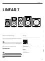 3
3
-
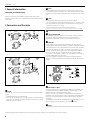 4
4
-
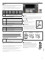 5
5
-
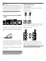 6
6
-
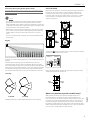 7
7
-
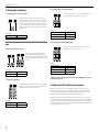 8
8
-
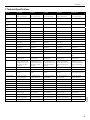 9
9
-
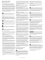 10
10
-
 11
11
-
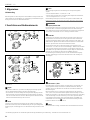 12
12
-
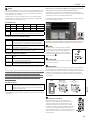 13
13
-
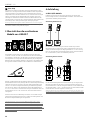 14
14
-
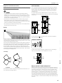 15
15
-
 16
16
-
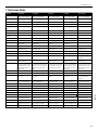 17
17
-
 18
18
-
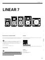 19
19
-
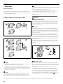 20
20
-
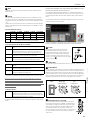 21
21
-
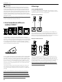 22
22
-
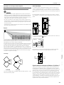 23
23
-
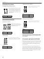 24
24
-
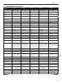 25
25
-
 26
26
-
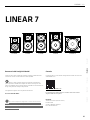 27
27
-
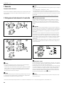 28
28
-
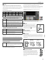 29
29
-
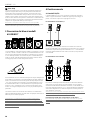 30
30
-
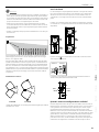 31
31
-
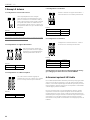 32
32
-
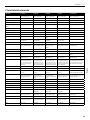 33
33
-
 34
34
-
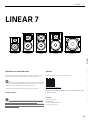 35
35
-
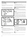 36
36
-
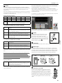 37
37
-
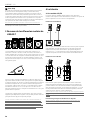 38
38
-
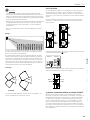 39
39
-
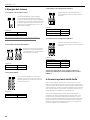 40
40
-
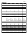 41
41
-
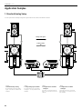 42
42
-
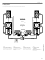 43
43
-
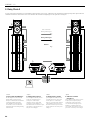 44
44
-
 45
45
-
 46
46
-
 47
47
-
 48
48


HK Audio LINEAR 7 112 XA Manuale utente
- Categoria
- Altoparlanti della soundbar
- Tipo
- Manuale utente