Jøtul GF 3 CF 2 Installation And Operating Instructions Manual
- Categoria
- Camini
- Tipo
- Installation And Operating Instructions Manual

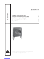
Jøtul GF 3 CF
Montering- og bruksanvisning - Norsk 2
Installation and Operating Instructions - English 12
Installatie- en montagehandleiding - Nederlands 22
Instrucciones para instalación - Español 32
Manuale di installazione ed uso - Italiano 44
Figures/Pictures 56
Jøtul GF 3 CF
Monterings- og bruksanvisningen må oppbevares under hele produktets levetid.
These instructions must be kept for future references.

2
Kvittering for installasjon
Ildstedet vil ved riktig bruk og vedlikehold tilfredsstille eieren i mange år. Kontakt din Jøtul forhandler for assistanse hvis
det skulle oppstå problemer med ditt Jøtul ildsted. Ta vare på denne bruksanvisningen og ha den tilgjengelig for
servicepersonell.
Modell navn: Jøtul GF 3 CF
Serie nr.:
Dato for kjøp:
Navn på installatør:
Type brensel:
Var ovnen konvertert ?:
Notater:
Årlig service – 1. år Sign.: Firma: Dato:
Utført arbeide:
Årlig service – 2. år Sign.: Firma: Dato:
Utført arbeide:
Årlig service – 3. år Sign.: Firma: Dato:
Utført arbeide:
Årlig service – 4. år Sign.: Firma: Dato:
Utført arbeide:
Årlig service – 5. år Sign.: Firma: Dato:
Utført arbeide:
Årlig service – 6. år Sign.: Firma: Dato:
Utført arbeide:
Årlig service – 7. år Sign.: Firma: Dato:
Utført arbeide:
Årlig service – 8. år Sign.: Firma: Dato:
Utført arbeide:
Årlig service - 9. år Sign.: Firma: Dato:
Utført arbeide:
Årlig service – 10. år Sign.: Firma: Dato:
Utført arbeide:
Årlig service – 11. år Sign.: Firma: Dato:
Utført arbeide:
Årlig service – 12. år Sign.: Firma: Dato:
Utført arbeide:
Årlig service – 13. år Sign.: Firma: Dato:
Utført arbeide:
Årlig service – 14. år Sign.: Firma: Dato:
Utført arbeide:
Årlig service – 15. år Sign.: Firma: Dato:
Utført arbeide:
Årlig service – 16. år Sign.: Firma: Dato:
Utført arbeide:
Årlig service – 17. år Sign.: Firma: Dato:
Utført arbeide:
Årlig service – 18. år Sign.: Firma: Dato:
Utført arbeide:
Årlig service – 19. år Sign.: Firma: Dato:
Utført arbeide:
Årlig service – 20. år Sign.: Firma: Dato:
Utført arbeide:
NORSK

3
Innhold
Kvittering for installasjon .......................................................... 2
Kvittering for årlig service......................................................... 2
Forhold til myndighetene
Tekniske data på Jøtul GF 3 CF ................................................ 3
Ekstrautstyr ................................................................................... 4
Sikkerhetsregler ........................................................................... 4
Installasjonsveiledning for kvalifisert personell
Krav til brannmur........................................................................ 4
Krav til gulvplate ......................................................................... 4
Plassering av ildstedet ............................................................... 4
Montering før installasjon........................................................ 4
Avtrekksystemet .......................................................................... 5
Installasjon av gass
Testing av gasstrykk ................................................................... 5
Kontroll av pilotflamme............................................................ 6
Årlig service ................................................................................... 6
Elektriske koblinger. ................................................................... 6
Forbrenningsprinsipp for gass ............................................... 6
Nødvendig varme under forbrenning .................................. 6
Generering av gnist ved pilothodet. ..................................... 6
Bruksanvisning
Opptenning................................................................................... 7
Tenningsinstruks
Tenning av pilotflamme............................................................ 7
Regulering av temperaturen ................................................... 7
Slukking av ildsted ..................................................................... 7
Feilsøking
Når det ikke genereres gnist ved pilothodet. ..................... 7
Gasstrykk ....................................................................................... 8
Når det ikke strømmer gass ved pilothodet ....................... 8
Når piloten slokner, feil ved gasstilførsel ............................. 8
Thermocouple .............................................................................. 8
Når piloten slokner, men gasstilførsel er ok........................ 9
Problemer med flammebildet. ............................................... 9
Vedlikehold
Utvendig vedlikehold ................................................................ 9
Sjekkliste ........................................................................................ 10
Tekniske tegninger ..................................................................... 56-57
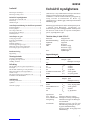
Forhold til myndighetene
Jøtul GF 3 CF, er et produkt som kun må fyres med enten
naturgass eller konverteres til å fyre med LPG.
Produktet er i samsvar med Forskrift om gassapparat og
utstyr, fastsatt av Direktoratet for Brann- og
eksplosjonsvern 5. oktober 1994, samt Europeisk standard
CEN EN 613 1998.
Montering og installasjon må utføres av kompetent person
i samsvar med: Montering-, installasjons- og
bruksanvisninger som er vedlagt produktet. Installasjonen
kan først tas i bruk når den er inspisert av kompetent
person, og ferdigattest er gitt.
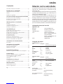
Tekniske data på Jøtul GF 3 CF :
Materiale: Støpejern/stål
Overflatebehandling: Emalje eller sort lakk
Røykuttak: Topp /bak
Røykrør: Ø 125 mm
Vekt: Produkt ca. 63 kg
kullsett ca. 6,3 kg
Vedsett ca. 5,3 kg.
ID-nr: 048BM 0036
Apparatkategori:
Kun vedkubber
Land Kategori Trykk
Naturgass/LPG G30/
G31
DK + SE + FI + NO II2H3B/P 20/30 mbar
AT I2H 20 mbar
LU + DE I2E 20 mbar
NL II2L3B/P 25/30 mbar
IT+GB+ES+PT+IE+CH+GR II2H3+ 20/28-37 mbar
FR/BE II2E+3E 20-25/28-37 mbar
Kun kullsett
Land Kategori Trykk
Naturgass/LPG G 31
AT+DK+FI+SE I2H 20 mbar
FR+BE II 2E+3P 20/25, 28-30/37 mbar
ES+CH+GB+IE+IT+PT II2H3p 20/28, 37 mbar
LU+DE I2E 20 mbar
NL: II2L3P 25, 30/50 mbar
Type brensel: Gass
Gass - kullsett: Naturgass G20/G 25, LPG G31
Gass-vedkubbesett: Naturgass G 20/G25, LPG G30/G31
Innregulering: Ildstedet er klargjort for Naturgass
G20 fra fabrikk.
Gassforbruk: Naturgass G 20: Ca. 0,52 m3/h ved
full belastning. Naturgass G 25: Ca.
0,55m3/h ved full belastning.
LPG G31 (4,8 kw): Ca. 0,34 kg/t ved
full belastning.
NORSK

4
LPG G30 (5,7 kw) ca. 0,41 kg/t ved full
belastning.
Tekniske data fortsettelse:
Tilført effekt kW: Naturgass G 20: Ca. 3 - 6,5 kW.
Naturgass G 25: Ca. 3 - 6,0 kW.
LPG G 31: Ca. 3,2 - 5,5 kW, (kun kull),
LPG G30/G31: Ca. 3,8 - 5,7 kW (kun
vedkubber)
Virkningsgrad: Min. 70%
Dyser: Hovedbrenner Pilotbrenner
Gass Merket Merket
G20 200 51
G 25 200 51
G31 (for kull) 140 30
G 30/31 (for ved) 130 30
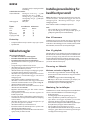
Ekstrautstyr
•Gulvplate i blåsort emalje. Størrelse: 632 x 772 x 17 mm.
•Fjernkontroll.
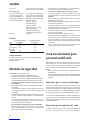
Sikkerhetsregler
Obs! Hvis gasslukt oppstår:
• Tenn ikke ovnen eller noe annet apparat.
• Bruk ikke elektriske brytere eller telefonen.
• Kontakt straks brannvesenet via nabotelefon.
• Ildstedet må kun installeres og repareres av kvalifisert
personell.
• Steng alltid av gasstilførselen før service.
• Ildstedet skal inspiseres etter installasjon og minst en
gang årlig av kvalifisert personell.
• Ildstedet må kun fyres med gass av riktig type og trykk.
Se tekniske data for nærmere informasjon.
• Ildstedet er innregulert med naturgass G20. Hvis LPG
skal benyttes, må ildstedet bygges om med et
ombygningssett.
Dette må kun installeres av kvalifisert personell.
• Ildstedet er tillatt montert mot vegg av brennbart
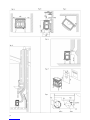
materiale med de avstander som er spesifisert i fig. 1-A.
• Ildstedet må kun installeres innendørs.
• Minimum avstand til brennbart materiale foran
ildstedet må være 600 mm.
• Oppbevar aldri brennbar gass eller væske i samme
rommet som ildstedet.
• Luftregulator på brennerrør må kun reguleres av
kvalifisert personell.
• Dersom noen deler av ildstedet har vært under vann,
må kvalifisert servicepersonell kontaktes for utbytting
av disse delene.
• Ildstedet skal ikke tennes uten at frontglasset er på
plass, eller hvis glasset er sprukket.
• Ildstedet skal ikke fyres med fast brensel.
• Brennbare materialer skal ikke plasseres på- eller nær
ildstedet, da ildstedet blir varmt.
• Vær oppmerksom på at ildstedet blir varmt slik at barn
og dyr holdes på sikker avstand.
Installasjonsveiledning for
kvalifisert personell
Viktig: Ildstedet er innregulert med naturgass G20. Hvis
LPG skal benyttes, må ildstedet bygges om med et
ombygningssett. Monteringsanvisningen følger
ombygningssettet.
Dette må kun installeres av kvalifisert personell.
Husk:
• Fylle ut skilt ”A” og plasser det bak på produktet.
• Fyll ut skilt ”B” og plasser det på tildelt plass på
godkjenningsskiltet (over ventilbraketten).
Krav til brannmur
Produktet kan plasseres direkte mot vegg av brennbart
materiale med de avstander som er beskrevet i fig. 1 . Se til
at det finnes tilstrekkelig plass for avtrekksystemet, både
bak ildstedet, samt for hele rørets høyde/lengde.
Krav til gulvplate
Ildstedet kan plasseres direkte på tregulv. Gulvplate av et
ikke brennbart materiale må benyttes hvis ildstedet skal
plasseres på teppe, vinyl, linoleum eller annet brennbart
material. Minimumsmål på gulvplate: 580 x 435 x 17 mm.
Til Jøtul GF 3 CF kan Jøtul levere gulvplater i blåsort emalje
(se avsnitt: Teknisk informasjon).
Plassering av ildstedet
Minimum avstander er følgende: (fig. 1)
• Avstand fra vegg til baksiden av ildstedet (fig. 1-B).
• Avstand fra brennbart materiale til topp av ildstedet
(se fig. 1-B)
• Avstand fra vegg til side av ildstedet (fig. 1-A).
NB! Høyre side krever minimum 250 mm(10”) for
betjening av kontrollknotten ved opptenning.
• Avstand fra hjørne til ildstedet (fig. 1-C).
Montering før installasjon
Produktet leveres i 2 kolli- ildsted og en brenner med kullsett
eller et sett med vedkubber. I brennkammeret ligger:
• Bruksanvisningen
• Et ombygningssett til LPG og Naturgass G 25.
• Etter at produktet er pakket ut, løftes toppen av.
•Fjern delene som ligger innpakket i plast under
topplaten. (Ett lite og ett stort røykhulldeksel)
• Glassrammen med glass løftes loddrett opp ved å åpne
de 2 fjærlåsene på toppen av brennkammeret.
• Delene pakket i plast som ligger inni, tas ut.
• Hvis produktet skal konverteres til annen gass enn G20
naturgass, gjøres dette nå. Se monteringsanvisningen
som følger konverteringssettet.
NORSK

5
• Pakk ut eskene med kullsettet evt. vedkubbene, og
brenneren.
Montering av brenner
• Følg nå monteringsanvisningen som følger kullsettet
evt. settet med vedkubber.
• Etter ferdig montering - sett glassrammen ned i sporene
igjen. Lås de 2 fjærlåsene på toppen av brennkammeret,
og se til at topplaten settes tilbake på rett plass.
• Benyttes toppmontering, plasseres det lille
røykhulldekselet på plass bak røykrøret.
• Ved bakmontering legges det største røykhulldekselet
på plass i topplaten.
• Installer askeleppen ved å hekte den på foran rett under
frontrammen -slik at den hviler på de to knastene på
frontrammen.
Avtrekksystemet
Mål røykuttak:
Innvendig = 128 mm
Utvendig = ca. 131 mm
Produktet kan også installeres med bruk av 100 mm (4")
rørkomponenter eller godkjente fleksible rør. Se fig. 5. Alle
avtrekksrør må installeres i henhold til godkjenning og til
produsentens instruksjoner.
Ved montering må lokale og nasjonale lover og regler på
området følges. Kun ett ildsted kan tilsluttes
avtrekkssystemet.
Avtrekksystemet skal skrus fast til ovnen og alle rørdeler
skal festes med skruer.
Avtrekkssystemet må avsluttes over tak (se fig. 1-d).
Minimum pipehøyde er ca. 2,15 m (7') og maksimum høyde
skal ikke være mer enn ca. 10,7 m (35'). (Ved installasjon i/
over ca. 610 m (2.000') høyde må pipehøyden, målt fra
røykuttaket, være minimum ca. 3,7 m (12'.)
Hvis det er nødvendig å forskyve pipen, må det benyttes
450 eller 900 bend (fig. 3).
Max. antall av 450 bend = 4
Max. antall av 900 bend = 3
Tillatt total forskyvning av pipen er ca. 1,2 m (4').
Ved avslutning av pipen må det monteres en avtrekkshette
(fig.1-d).
Installasjon av gass
Gassinstallasjon må kun utføres av personer med
kompetanse. Lokale og nasjonale lover og regler på området
må følges.
Gassbeholderen må oppbevares/installeres i hht. Lov av 21.
mai 1971 nr 47 ”Lov om brannfarlige varer samt vesker og
gasser under trykk” samt forskrifter .
Gassbeholderen må ha en trykkregulator som reduserer
trykket til riktig trykk. (Se tekniske data for gasstype og
trykk før tilslutning til ildstedet. Ildstedet må ikke utsettes
for gasstrykk over 55 mbar (5,5 kPa) ved trykktesting.
Gassrør må være av stål (DIN 2448/1629, DIN 2458/1626,
DIN 2440, DIN 2441) eller kobber (DIN 2110).
Avtrekksystemet bør av praktiske årsaker monteres før
ildstedet blir tilkoblet gasstilførselen.
• Gassventilen har en klemringsmutter og en klemring
for 8 mm kobberrør.
• Alle rørforbindelser skal være godkjent for LPG.
• Gassledningen må ha godkjent avstengningsventil, og
ved alle rørforbindelser må det kun brukes godkjent
tetningsmiddel (tape).
• Etter ferdigmontering av rørforbindelser og tilkobling
av ildstedet- åpnes gasstilførselen og ildstedet tennes
(se tenningsinstruks). Samtlige rørforbindelser
tetthetsprøves.
Testing av gasstrykk (Fig. 3)
Korrekt gasstrykk er viktig for sikker fyring med gass i
ildstedet. Installatøren må sjekke at gasstrykket er korrekt
ved installasjon av ildstedet. Gassventilen er utstyrt med
uttak for test av gasstrykk. Uttakene befinner seg under
på høyre side av ildstedet
Høyre uttak (A): For gasstrykk tilførselen til ventilen
(mengden av gass til ventilen). Se tekniske data.
Venstre uttak (B): For gasstrykk fra ventilen (mengden av
gass som kommer ut av ventilen til brenneren).
• Test alltid gasstrykket med ventil kontrollknotten fullt
åpen.
• Skruen i uttaket løsnes, og slangen fra manometeret
settes på uttak.
• Husk å stramme denne skruen igjen etter målingen er
utført.
Justering av gasstrykk (fig. 3)
• Gasstrykket justeres med et lite skrujern ved å skru på
justerskruen, som er plassert midt på ventilen mellom
gasskontroll knottene (fig. 3 - E).
• Vri gasstilførselen til lav og juster det nedre gasstrykket
ved å bruke skruen som vist i fig. 3 - F.
Se: Testing av gasstrykk og skjemaet for nødvendig
gasstrykk.
NB! Gasstrykket er forskjellig ved kald og varm ovn.
NORSK

6
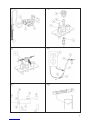
Kontroll av pilotflamme
Pilotflammen skal ha tre flammetunger som vist i fig. 4
Termoelementstaven skal være omkranset av
flammetunger (som vist i figuren.) Flammene skal være
stabile, og farven skal i hovedsak være blå. Ved avvik skal
pilotflammen slukkes og service tilkalles.
Årlig service
Årlig kontroll av ildstedet omfatter følgende
kontrollpunkter.
• Tenning av pilotflammen.
• Rengjøring av glasset.
• Pakningen rundt glasset skal kontrolleres årlig mht.
eventuelt slitasje, og skal skiftes hvis nødvendig.
• Kontroller gasstrykket, hvis annet gassutstyr er tilkoplet
gasstilførselen.
• Se etter tegn på korrosjon på ildstedet eller
avtrekkssystemet.
• Se etter blokkeringer i avtrekkssystemet (f. eks
fuglereder, eller grener fra trær og busker.
Elektriske koblinger - Termostat
(fig. 5)
Fig. 5 viser hvordan produktets ledningerne er koblet.
Tabellen nedenfor viser beskrivelse av posisjonsnummerne
til figuren. Legg merke til at dersom produktet skal styres
med fjernbetjening , må motor (G) kobles til ventilen (F).
Batteriboksen (H) kobles til motoren ved hjelp av en ledning,
og henges bak på skjermplaten. Kontakt din forhandler for
evt. levering av slikt utstyr.
Beskrivelse av deler til koblingsskjema.
A Thermocouple
B Sikkerhetsbryter
C El-kabel til sikkerhetsbryter
D El-avbryter
E Termostat
F Ventil
G El-motor (tilleggsutstyr)
H Batteriboks (tilleggsutstyr)
I Fjernbetjening (tilleggsutstyr)
Forbrenningsprinsipp for gass
Det må være 3 hovedelementer til stede for å oppnå en
forbrenning. De 3 elementene er: Varme, brensel samt
oksygen. Hvis ett av hovedelementene forandres kan det
resultere i ufullstendig forbrenning. Disse basis elementer
er viktige å huske på når man utfører feilsøking. Forbrenning
kan ikke skje hvis en av disse 3 elementer mangler.
Oksygenblanding:
Naturgass: 10 m3 oksygen til 1m3 naturgass
LPG: 24 m3 oksygen til 1 m3 LPG
Nødvendig varme under forbrenning
Konstant flammevarme under fyring er kritisk for komplett
forbrenning. Installatøren og personen som utfører service
må være nøye når de keramiske vedkubbene/kullsettet
legges på plass. Kunden må også gjøres oppmerksom på
dette.
Hvis de keramiske vedkubbene/kullene ligger i veien for
flammen, kan det resultere i at de tiltrekker seg varmen
fra flammen og derved senker flammetemperaturen.
Dette vil resultere i ufullstendig forbrenning, dårlig
flammebilde og høyere karbon monoxid (CO) verdier. Høy
CO-produksjon kan medføre sot på de keramiske
vedkubbene, glasset og utvendig på bygningen.
Generering av gnist ved pilothodet
Jøtul GF 3 CF har ventil med innebygget gnisttenner. Når
kontrollknotten trykkes i bunn og vris, genereres en gnist
på 920°C. Denne ledes via en isolert ledning til
pilotbrenneren, hvor den er festet med keramisk isolering.
Den varme gnisten springer fra spissen av tenneren, som
kalles elektroden, til pilothodet, og tilbake igjen til
jordforbindelsen. Den varme gnisten er mer enn nok for å
antenne både naturgass og LPG.
Gnisttenneren i gassovnen gir: 920°C
Naturgass krever: 620°C
LPG krever: 500-600°C
NORSK
Nødvendig gasstrykk til/fra ventilen:
Gasstype Høyre uttak (A) Venstre uttak (B) Varm ovn Venstre uttak (B) Kald ovn
Tilført gasstrykk Justering av trykk Justering av trykk
Høy Lav Høy Lav
Nat.Gas G 20 20 mbar 14,5 mbar 3,6 mbar 13,6 mbar 3,1 mbar
Nat.Gas G 25 25 mbar 18,0 mbar 3,6 mbar 17,0 mbar 3,1 mbar
LPG G31 (kun kullsett) 30/37 mbar 17,4 mbar 8,9 mbar 16,3 mbar 8,4 mbar
LPG G30/G31 (kun vedkubber) 30/37 mbar 23,0 mbar 8,9 mbar 21,9 mbar 8,4 mbar

7
Bruksanvisning
Opptenning
NB! Lukt under fyring:
Under første gangs oppfyring gir ildstedet fra seg en
irriterende gass som kan lukte noe. Gassen er ikke giftig,
men det bør foretas en skikkelig utlufting av rommet.
Ved første opptenning kan det ta litt tid før gassrøret blir
tomt for luft, men deretter skal ildstedet virke som
beskrevet i tenningsinstruksen.
Ildstedet virker ved hjelp av en pilotflamme som må tennes
manuelt i følge tenningsinstruksen.
Før tenning; Sjekk området rundt ildstedet for eventuell
gasslekkasje/lukt. Undersøk spesielt nær gulvet, da LPG er
tyngre enn luft, og ved en eventuelt lekkasje vil gassen
samles der.
(NB! Naturgass er lettere enn luft og vil stige til opp under
taket).
Hvis gasslukt skulle merkes, se advarsel under:
Sikkerhetsregler. Bruk kun hånden (ikke verktøy) for
betjening av kontrollknottene. Hvis kontrollknotten ikke kan
vris eller trykkes inn - ikke bruk makt, men tilkall service.
Ikke bruk ildstedet hvis noen del av det har vært under
vann. Tilkall service og få deler som har vært under vann
skiftet ut.
Tenningsinstruks
Tenning av pilotflamme (fig. 2)
Kontrollknottene befinner seg på høyre side av ildstedet
1. Sjekk at gassventilen på rørledningen til ildstedet er
åpen.
2. Se til at knotten (2) er i posisjon (max.)
3. Vri gasskontrollknotten (1) litt mot venstre (til Ignition)
til den stopper. Trykk inn- og hold knappen inne i ca 5
sekunder. Vri så mot klokken til til det høres en knepping.
Dette kan gjentas til du ser pilotflammen nederst til
venstre i brennkammeret.
4. Fortsett å holdeknappen inne i ca 10 - 15 sekunder, før
den slippes.
5. NB: Gasskontrollknotten kan ikke vris før den blir trykket
noe inn. Bruk ikke makt.
6. Vri så knappen (uten å trykke inn) helt over til «ON»
(mot tegnet for høy flamme).
Hvis pilotflammen ikke vil forbli tent.
Skru knotten (1) mot høyre til den stopper - trykk den inn og
vri helt mot høyre til «Off». Kontakt service.
NB! Første gang ildstedet tennes vil det kunne dannes
kondens i brennkammeret. Det vil også kunne ose litt fra
ildstedet de første timene på grunn av avbrenning av
maling og smøring brukt under fremstillings-prosessen. Se
avsnittet: Lukt under innfyring.
Regulering av temperaturen
Ildstedet bør ha vært i drift min. 45 minutter før
temperaturen justeres.
•For å justere temperaturen, benyttes knotten til venstre
(fig. 2- 2). Denne har en skala fra min. til max. Dette
tilsvarer ca fra 15 o til 45 o .
•Vri knotten til ønsket varmeavgivelse.
Slukking av ildsted
For å slukke ildstedet helt, må gasskontrollknotten (fig 2-1)
trykkes ned og vris med klokken til ”OFF”. Bruk ikke makt.
Feilsøking
Når det ikke genereres gnist ved
pilothodet (fig. 6)
Det er sjeldent at gnisttenneren feiler, hvis den ikke er
fysisk ødelagt. Når gnisten ikke videreføres kan det skyldes
brudd i det elektriske kretsløpet før det når pilothodet.
Gnisten er ”liten” eller svak pga. ved for stor motstand hvis
det er en knekk på ledningen, eller ved korrosjon ved
elektroden (A) eller pilothodet (B). Dette kan føre til
utilstrekkelig varme for å antenne gassen.
Sjekk pilotbrenneren ved å se etter skade på de enkelte
deler. Sjekk om ledningene har skader eller er klemt imellom
platedeler på ildstedet, og kontroller om det er løse
forbindelser.
Følgende fremgangsmåte for feilsøking kan
benyttes når det ikke genereres gnist ved
pilothodet (fig. 6):
• Sjekk at gnistgapet mellom elektrode (A), og pilothodet
(B) er mindre eller lik med 3,2 mm.
• Hvis ikke: Se til om elektroden er løs eller skadet
• Sjekk at den isolerte ledningen er intakt og uten knekk,
samt i fast forbindelse mellom ventilen og elektrode
(A).
• Hvis ikke: Den isolerte ledningen festes for å oppnå
forbindelse mellom gnistenneren og elektroden.
Elektroden byttes ved skade eller knekk på ledningen.
• Sjekk at den keramisk isoleringen (C) er hel og uten
sprekker
• Hvis ikke: Skift ut elektroden.
NORSK

8
Gasstrykk
Korrekt gasstrykk er viktig. Se derfor avsnittet om gasstrykk
under gassinstallasjon. Både gasstrykket før ventilen og
trykket ut fra ventilen til hovedbrenner og pilot brenner er
viktig. Disse parametrene kan være årsak til forskjellige
problemer med ildstedet, for eksempel:
For lavt gasstrykk vil resultere i:
Lav pilotflamme, dårlig strømprodusering ved
thermocouple og dårlig flammebilde.
For høyt gasstrykk vil resultere i:
Ekstreme tilfeller hvor ventilen skades når trykket stiger
til over 60 mbar. Dette er vanligvis et resultat av feil
installering eller mangel på gassregulator på gasstank eller
flaske. Et for høyt gasstrykk kan også resultere i unormalt
stor pilotflamme- noe som kan overhete thermocouple,
og videre resultere i avstenging av ventilen pga. for liten
millivoltproduksjon.
Problemer med høye flammer og sot tyder på for liten
luftmengde i forhold til gassmengden.
Ved å sjekke gasstrykket før ventilen, kan feil i
gasstilførselen ved ventil eller fra tank/flaske oppdages.
Ved korrekt gasstrykk til ventil må feilen finnes etter
ventilen. Med en måling utført med manometer (fig. 3) kan
man hurtig oppdage og eliminere feilkilder. Blokkert eller
dårlig gasstilførsel kan som nevnt medføre feil forbrenning.
Det må sjekkes om alle gassrør er fri for smuss, da et lite
støvkorn kan blokkere pilotdysen. Komponentene må
holdes fri for smuss når gasstilførselen monteres og koples
til ildstedet, samt ved utskiftning av ventil.
Når det ikke strømmer gass ved
pilothodet:
Følgende fremgangsmåte benyttes for å
sjekke feil med gasstilførselen:
• Sjekk om alle gasskoplinger er tette ved å bruke sterkt
såpevann (unngå syntetisk såpe).
• Sjekk deretter om alle ventiler er åpne fra gass tanken/
flasken.
• Når piloten skal tennes for første gang ved ny
installasjon, etter en planlagt avkopling, eller etter at
LPG tanken har f ått påfyll, er det ofte luft i gassrøret
inntil ildstedet. Det er nødvendig å tømme rørsystemet
for luft før pilotbrenneren kan tennes. Den anbefalte
måte å tømme rørsystemet for luft på, er å trykke
gasskontrollknotten inn og vri mot klokken. Prosedyren
gjentas inntil piloten tenner.
• Hvis piloten ikke vil tenne etter forsøk på å tømme
rørsystemet for luft, tyder det på feil med gasstanken/
flasken eller lekkasje på gassrøret. Sjekk gasstrykket
som beskrevet under gassinstallasjon, og kontroller om
feilen/lekkasjen er før eller etter ventilen på ildstedet.
Hvis gasstrykket er for lavt på uttak (A - fig. 3), eller det
ikke er noe gasstrykk, må feilen eller lekkasjen lokaliseres
før ventilen på ildstedet. Hvis gasstrykket er i orden på
uttak (A), men for lavt på uttak (B), må feilen eller
lekkasjen finnes etter ventilen.
• NB! Mertik Maxitrol Ventilene er alltid utstyrt med et
fint filter på innløpet for å forhindre smuss i å trenge
inn i ventilen. Av den grunn er det sjeldent smuss inne i
ventilen.
• Hvis gassrør demonteres, må alle gassrør monteres og
sjekkes for gasslekkasje før ildstedet tas i bruk.
Når piloten slokner - feil ved
gasstilførsel:
Følgende fremgangsmåte benyttes for å
sjekke feil med gasstilførselen:
• Husk å trykke inn gasskontrollknotten (fig. 2-1) i 15
sekunder.
• Sjekk om flammen er sentrert på thermocouple.
• Sjekk om thermocouple er omsvøpt av flammen til
minimum 3mm (1/8”) fra spissen (fig.4).
• Hvis flammen er unormalt stor, eller liten, sjekkes først
gasstrykket. Se avsnitt om gasstrykk.
• Sjekk deretter for feil, smuss eller korrosjon på
pilotbrenneren (6-B) pilotdysen (6-D) og gasstilførselen
(6-E) til pilotbrenneren.
NB! Det kan være lekkasje etter ventilen selv om trykket er i
orden på venstre uttak. Derfor, sjekk alltid for lekkasje.
Thermocouple (fig.4)
Thermocouple er i prinsippet en termisk generator og
består av en kobbertråd (kobber-nikkellegering) og en
jerntråd, som er viklet sammen. Disse trådene vil skape
gnidning, og genererer 25 milivolt når de utsettes for en
temperaturforskjell på 200°C. Denne spenningen (volt) vil
være nok til at gassventilen fungerer.
Dette er viktig å vite at selv en liten motstand (ohm) vil ha
stor påvirkning på en spenning som er så liten. For stor
motstand kan medføre at gassventilen ikke får nok
spenning til å fungere. Årsaken til for stor motstand kan
være for lang kobberledning hvor spenningen skal
overføres, eller for mange forbindelser. Hvis
kobberledningen kommer i berøring med metall kan
motstanden øke, og derved forminske spenningen.
NORSK

9
Når piloten slokner, men
gasstilførselen er ok:
Følgende fremgangsmåte benyttes for å sjekke
feil med thermocouple.
• Sjekk kobberledningen til thermocouple for knekk eller
skader.
• Pakningen ved ventilen sjekkes ved å løsne mutteren
som fester kobberledningen. Se etter tegn på skader,
hvis mutteren har vært strammet for hardt. Ødelagt
pakning medfører stor motstand ved metallkontakt, og
dermed for lav spenning til ventil.
• Sjekk om flammen er sentrert på thermocouple.
• Sjekk om thermocouple er omsvøpt av flammen til
minimum 3mm fra spissen (fig. 4).
• Sjekk spenningen som produseres av thermocouplen.
Multimeteret (fig.7-E) kobles med pluss til
kuleavslutningen (fig. 7-D) i enden av kobberledningen.
Minus kobles til kobberledningen.
• Piloten tennes (fig. 7-A) og kontrollknotten holdes inne
for å hindre at flammen på pilotbrenneren slukkes.
• Multimeteret skal nå vise 14-28mV.
Hvis det er i starten på en ny fyringssesong og ildstedet
ikke har vært i bruk, kan det dannes en film på spissen av
thermocouple. Denne filmen kan pusses bort med fint
slipepapir. Ved utskiftning av thermocouple brukes en 9
mm fastnøkkel. Mutteren på thermocouple må ikke
strammes for hardt, men kun en halv omgang.
Problemer med flammebildet
Produktet er justert fra fabrikk. Skulle det oppstå problemer
med flammebildet, må settet med vedkubber, evt. kullsett,
demonteres. Sjekk så om luftregulatoren er riktig montert.
(Se monteringsanvisning til konverteringssett).
Hvis avtrekksystemet har liten loddrett stigning, kan det
skje at flammene trekker ut mot glasset. Dette kan skyldes
at mengden luft til forbrenningen fremme mot glasset
blir for liten.
For å motvirke dette er det stanset ut 2 felter i
frontbrakettens bakside, som kan bøyes inn. Dette vil gi
mer luft til forbrenningen. (Se fig. 8.)
Innstillingen kan variere ved forskjellige installasjoner, og
man må prøve seg fram for å finne den beste luftåpningen.
For stor åpning kan resultere i for små flammer.
NORSK
Vedlikehold
Hele installasjonen, inkludert tilførsel av gass, selve
ildstedet og avtrekksystemet, skal gjennomgå ettersyn en
gang årlig. Dette skal gjennomføres av kompetent
servicepersonell.
Utvendig vedlikehold
Lakkerte produkter vil etter noen års bruk kunne endre farve.
Overflaten bør pusses og børstes fri fra løse partikler før
ny ovnslakk påføres.
Emaljerte produkter skal kun tørkes med en tørr klut. Vann
eller såpe skal ikke brukes. Eventuelle flekker fjernes med
egnet rensemiddel (Stekeovnsrens el.l.).

10
NORSK
Dato:___________________
Sign:_________________________________________
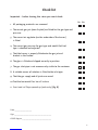
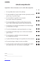
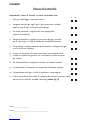
Sjekkliste
Ja Nei
Er det sjekket at all emballasje er fjernet?
Er det sjekket hvilken gasstype som skal benyttes?
Er produktet konvertert til riktig gasstype?
Hoveddyse - er det riktig dyse i henhold til gasstype?
Pilotdyse - er det riktig dyse i henhold til gasstype?
Luftregulatoren, under brenneren - er den justert?
Avtrekket - har dette minst 2% stigning?
Er lekkasjetesting av rørforbindelser utført?
Riktig trykkinnstilling - sjekk tabell.
Sjekk flammebildet - vent 15 - 25 minutter.
Utfylling av skilt A og B - er de plassert på riktig sted?
Gasstrykket - er det sjekket og justert
riktig i forhold til modell og type gass?
Er det sjekket at glasset sitter godt?
Er feltene i frontbrakettens bakside bøyd inn?
(Kun ved kullsett) Se fig. 8)


12
ENGLISH
Installation signature form
With proper usage and maintenance, this fireplace will serve its owner adequately for many years. Please contact your
Jøtul dealer for assistance if any problems should arise with your Jøtul fireplace. Hold on to this user manual and make sure
it is available for service personnel.
Model name: Jøtul GF 3 CF
Serial no.:
Purchase date:
Name of installer:
Fuel type:
Was the stove converted?:
Notes:
Annual service - year 1 Sign.: Company: Date:
Service details:
Annual service - year 2 Sign.: Company: Date:
Service details:
Annual service - year 3 Sign.: Company: Date:
Service details:
Annual service - year 4 Sign.: Company: Date:
Service details:
Annual service - year 5 Sign.: Company: Date:
Service details:
Annual service - year 6 Sign.: Company: Date:
Service details:
Annual service - year 7 Sign.: Company: Date:
Service details:
Annual service - year 8 Sign.: Company: Date:
Service details:
Annual service - year 9 Sign.: Company: Date:
Service details:
Annual service - year 10 Sign.: Company: Date:
Service details:
Annual service - year 11 Sign.: Company: Date:
Service details:
Annual service - year 12 Sign.: Company: Date:
Service details:
Annual service - year 13 Sign.: Company: Date:
Service details:
Annual service - year 14 Sign.: Company: Date:
Service details:
Annual service - year 15 Sign.: Company: Date:
Service details:
Annual service - year 16 Sign.: Company: Date:
Service details:
Annual service - year 17 Sign.: Company: Date:
Service details:
Annual service - year 18 Sign.: Company: Date:
Service details:
Annual service - year 19 Sign.: Company: Date:
Service details:
Annual service - year 20 Sign.: Company: Date:
Service details:

13
Table of contents
Installation signature form ..................................................... 12
Annual service signature form ............................................... 12
Relationship to the authorities
Technical data of Jøtul GF 3 CF .............................................. 13
Optional equipment ................................................................. 14
Safety precautions ..................................................................... 14
Installation guide for qualified personnel
Firewall requirement ................................................................ 14
Requirements for the floor plate .......................................... 15
Position of theappliance .......................................................... 15
Assembly prior to installation ................................................ 15
The vent system.......................................................................... 15
Closure plate installation ......................................................... 15
Gas installation
Testing gas pressure .................................................................. 16
Testing the flue system ............................................................16
Regulating the pilot flame ...................................................... 17
Annual service ............................................................................. 17
Electrical connections................................................................ 17
Operating instructions
Lighting instructions ................................................................. 17
Adjusting the temperature ...................................................... 18
Turning off the fireplace...........................................................18
The combustion principle for gas ......................................... 18
Required heat during combustion ....................................... 18
Generation of sparks at the pilot head ...............................18
Trouble-shooting
When no spark is generated at the pilot head.................. 18
Fuel gas
When there is no gas flow at the pilot head .....................19
When the pilot goes out, problems with the
gas supply .................................................................................... 19
Thermocouple ............................................................................. 19
When the pilot goes out: ........................................................ 20
Problems with the flame pattern......................................... 20
Maintenance
External maintenance .............................................................. 20
Check list ....................................................................................... 21
Technical drawings ............................................................. 56-57
Read all these instructions before installation &
use of this appliance.
Relationship to the
authorities
This product, the Jøtul GF 3 CF, may only be used with Natural
Gas G20 or be converted for the use of Natural Gas G25,
LPG.
This product is in accordance with Regulations for Gas
Appliances and Equipment, established by the European
Standard CEN EN 613 1998.
Assembly and installation must be performed by a qualified
person in accordance with the instructions for assembly,
installation and use enclosed with the product and other
national and local rules in force. In the UK this includes the
Gas Safety (Installation & use) Regulations 1998. The
installation may only be operated after it has been
inspected by a qualified person and a certificate of
completion has been issued.
Technical data of Jøtul GF 3 CF
Material: Cast iron/steel
Finish: Enamel or black paint
Flue outlet: Top/Rear
Flue pipe: 125 mm dia.
Weight: Product approx. 63 kg
Coal set approx. 6,3 kg
Log set approx. 5,3 kg.
ID no.: 048BM 0036
Appliance category:
Logs only:
Country Category Pressure
Natural Gas/LPG G30/
G31
DK + SE + FI + NO : II2H3B/P 20/30 mbar
AT : I2H 20 mbar
LU + DE : I2E 20 mbar
NL : II2L3B/P 25/30 mbar
IT+GB+ES+PT+
IE+CH+GR : II2H3+ 20/28-37 mbar
FR/BE : II2E+3E 20-25/28-37 mbar
Coals only:
Country Category Pressure
Natural Gas/LPG G31
AT+DK+FI+SE I2H 20 mbar
FR+BE II 2E+3P 20/25, 28-30/37 mbar
ES+CH+GB+IE+IT+PT II2H3p 20 / 28, 37 mbar
LU+DE I2E 20 mbar
NL: II2L3P 25, 30/50 mbar
ENGLISH

14
Fuel: Gas
Gas-coal set: Natural Gas G20/ G 25, LPG G31
Gas - log set: Natural Gas G20/G25, LPG G 30/G31
Presetting: The appliance is prepared from the
factory for Natural Gas G20.
Gas consumption: Natural Gas G 20: approx. 0,52 m3/hr
at full capacity. Natural Gas G 25:
approx. 0,55 m3/h. LPG G 31 (4,8 kW):
approx. 0,34 kg/hr at full capacity
LPG G 30 (5,7 kW) approx. 0,41 kg/hr
at full capacity.
Input effect kW: Natural Gas G 20: Approx. 3 - 6,5 kW,
Natural Gas G 25: Approx. 3 - 6,0 kW,
LPG G 31: Approx. 3,2 - 5,5 kW.
(Coals only).
LPG G 30/31: ca. 3,8 - 5,7 kW.
(Logs only).
Efficiency: Min. 70%
Orifices:
Main burner Pilot burner
Gas Labelled Labelled
G20 200 51
G 25 200 51
G31 (coals only) 140 30
G30/31 (logs only) 130 30
Optional equipment
• Floor plates in blue-black enamel. Size: 632x772x17mm.
• Remote control
Safety precautions
If leaving the appliance unattended for any time, always
turn the main control knob to the pilot only or off position.
Warning! If you detect an odour of gas:
• Do not light the stove or any other appliance.
• Do not use electrical switches or the telephone.
• Contact the fire department immediately from a
neighbour’s telephone.
• This appliance does not normally require extra fixed
ventilation to be installed, but must be fitted to a
correctly functioning flue system in a sufficiently
ventilated space. This is to provide correct air suppply
for combustion and proper operation of the flue.
General safety precautions
• The appliance must only be installed and repaired by
qualified personnel.
• If there is a fault with the appliance affecting operation
or ignition, it must only be rectified by qualified
personnel. Do not use the appliance whilst a fault is
suspected and NEVER attempt Do It Yourself repairs, it
can cause serious damage and danger.
• Always turn off the gas supply before service.
• The appliance must be inspected following installation
and inspected and serviced at least once a year by
qualified personnel.
• The appliance must only use gas of the correct type
and pressure See technical data for more details.
• The appliance is pre-set for natural gas G20. If natural
gas G25 or LPG is to be used, the fireplace must to be
converted with a conversion kit.
This is only to be installed by qualified personnel.
• It is permitted to install the appliance against a wall
made of combustible material with the clearances
specified in fig. 1- A
• The appliance must only be installed indoors.
• The minimum clearance to combustible material directly
in front of the appliance is 600 mm.
• Never store combustible gas or liquid in the same room
with the appliance.
• The air regulator on the burner tube must only be
adjusted by qualified personnel.
• If any parts of the appliance have been submerged in
water, contact qualified service personnel to replace
these parts.
• Never light the appliance without the front glass in place
or if the glass is cracked.
• Do not burn solid fuel in the appliance.
• Do not place combustible material on or near the
appliance, as the fireplace becomes hot.
• Be aware that the appliance becomes hot and make
sure to keep children and animals at a safe distance.
Installation guide for
qualified personnel
Important: The appliance is factory pre-set for Natural Gas
G20. If natural Gas G25 or LPG are to be used, the fireplace
must be converted with the conversion kit. The installation
instruction is included with the conversion kit.
Note:
• Fill in and place the label “A” at the back of the delayed
ignition door (at the back of the product).
• Fill in and place the label “B” at the assigned spot on the
approval label (above the valve bracket).
Firewall requirements
The appliance may be placed directly against a wall made
of combustible material with the clearances specified in
fig. 1 . Make sure there is adequate space for the vent
system behind the appliance and for the full height/length
of the pipe. Pipe sections of the vent system can not be
closer to combustible material than 25mm for a vertical
pipe and 50mm for a horizontal pipe.
ENGLISH

15
Requirements for the floor plate
The appliance may stand on a wooden floor. A floor plate
of non-combustible material is required if the appliance is
to be placed on carpet, vinyl, linoleum or other combustible
material. Minimum dimensions of the floor plate: 580 x
435mm. Jøtul can supply floor plates in blue black enamel
for the Jøtul GF 3 CF (see section about optional
equipment).
Position of the appliance
Minimum clearances are as follows: (fig. 1)
• Clearance from wall to rear of appliance, (fig. 1-B).
• Clearance from wall to side of appliance ( fig. 1-A).
Note! The right side requires at least 250mm(10”) for
the operation of control knobs for lighting.
• Clearance from corner to appliance, (fig. 1-C).
Assembly prior to installation
The product is delivered in 2 packages - the stove and a
coal kit or a ceramic logset.
Included in the fire box:
• The instruction booklet.
• A convertion kit for LPG and Natural Gas G 25.
Mounting
• When the product has been unwrapped, lift off the top.
•Take out the parts wrapped in plastic under the top
plate. (A small and a large cover for the flue outlet)
• Lift the glass frame with the glass straight up by opening
the 2 latches at the top of the fire box.
• Remove the parts wrapped in plastic inside the stove.
If the product is going to be used with another type of
gas than G20 natural gas, it should be converted now.
See the manual for the conversion kit.
• Unwrap the box containing the log set/coal set. The
box contains also a burner.
Mounting of the burner
• Follow the installation instructions which are included
with the burner/ coal set or log set.
• After mounting - put the glasframe down back in its
track, and be particular about mounting the top plate
correctly on its mountings.
• When installing a top flue outlet, the small flue outlet
cover is to be placed on the rear of the flue pipe.
• When installing a rear flue outlet, the large cover has to
be put in place in the top plate
• Install the ash lip by hooking it onto the front, just below
the front frame. It should bear against the two cams
on each side of the front frame.
The vent system
Flue outlet (spigot) dimensions:
Internally = 128 mm
Externally = approx. 131 mm
The product may also be installed using 100 mm (4") pipe
components or approved flexible pipes. All vent pipes must
be installed according to approval and the instructions of
the manufacturer.
When installing the vent, it is important to adhere to
national and local regulations that apply. Only one fireplace
may be connected to the vent system.
The vent system must terminate above the roof.
The vent system and the flue pipe components must be
fastened to the stove with screws.
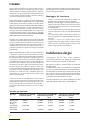
Minimum height of the chimney is approx. 2,15 m (7') and
maximum height should not be more than approx. 10,7 m
(35'). (When installation is at or above a height of approx.
610 m (2000'), the chimney’s height must be at least approx.
3,7 m (12'.) measured from the flue outlet.
If the chimney has to move through a horizontal distance,
make sure to use 450 or 900 bends (fig. 3).
Max. number of 450 bends = 4
Max. number of 900 bends = 3
It is permitted to move the chimney a total of approx. 1,2 m
(4')horizontally.
An exhaust hood (terminal, cowl or rain cap) must be
mounted at the chimney’s termination point (fig. 1-d).
After fitting of the vent system and installation of the
appliance, carry out a smoke test on the flue as described
in the relevant section.
If the appliance shuts off in operation for no apparent reason
(especially during windy or stormy conditions) and will not
relight, it is possible that the flue system safety switch has
operated. Allow the appliance to cool down and relight. Any
obstruction to the flow of exhaust gases up the flue can
cause this switch to operate thereby making the situation
safe. If the appliance cuts out repeatedly, do not continue to
use the appliance and seek flue checking and service from
qualified personnel before re-using the appliance.
Closure Plate Installation (fig. 1 E-F)
It is permissible to install this appliance using a closure
plate installation similar to traditional outset gas fires. See
diagrams (1 E-F) on page 56. The British Standards detailing
this type of installation are BS5871 pt1 and BS5440 pt 1.
The fireplace and flue must be sound and if used with solid
fuel or oil appliances it must be swept prior to installation.
There must be no other openings other than the exit from
the top of the flue and the opening into which the appliance
is being installed. All cracks, holes, underfloor air vents etc
must be removed and sealed fully before installation
continues. A proprietary metal flue box complying with BS715
is a suitable fireplace opening.
ENGLISH

16
ENGLISH
All brick flues or any flue previously used with solid fuel or
gas appliances must be left with the appropriate debris
collection volume below the flue spigot of the stove of 12
lites minimum, and depth of 250mm minimum below the
spigot. Block, clay, cement or steel lined (connected to the
top of the fireplace opening) flues either new or previously
used with GAS appliances may have the smaller debris
collection volume of 2 litres minimum and depth of 75mm
minimum below the flue spigot.
Make sure that there will be at least 50mm clearance
between the end of the spigot and knee of the fireback for
flue gasses. Also make sure that the spigot will pass through
the closure plate by a minimum of 15mm. It can be extended
by up to 150mm (6") to ensure this requirement is met
using a purpose made extension or suitable piece of flue
pipe.
Cut a closure plate from sheet aluminimum or steel to just
cover the fireplace opening to be used. It is also possible to
use other fireproof materials providing they are properly
supported and sealed and can be removed annually for
inspection and clearing of the flue. Cut a spigot hole as
shown in the diagram. Fix the closure plate to the wall or
fireplace and seal it correctly to the wall. The plate must be
sealed correctly to the wall using adhesive sealant, screws
and/or tape able to withstand at least 3 degrees C. The
appliance will not work correctly and may cut out
repeatedly if the sealing of the fireplace and flue is not
correct.
Remember if the closure plate will show around the sides
or top of the stove, a non combustible decorative panel
can be fitted to cover the area. The closure plate can then
be fitted to this. Marble infill panels are a common
example.
Install the appliance and connect to the gas supply and
carry out a smoke test on the flue as described in the
relevant section.
Gas installation
Gas installation must only be performed by qualified
personnel. It is important to adhere to national and local
regulations that apply.
The gas container must be stored/installed according to
regulations.
The gas container must have a pressure regulator that
reduces the pressure to the required level. (See technical
data for gas type and pressure before connecting to the
fireplace. The appliance must not be exposed to pressure
above 55 mbar (5,5 kPa) during pressure testing.
Gas tubes must be made of steel (DIN 2448/1629, DIN 2458/
1626, DIN 2440, DIN 2441) or copper (DIN 2110).
For practical reasons, the vent system should be installed
before the appliance is connected to the gas supply.
• The gas valve has a compression ring nut and a
compression ring for 8 mm copper tube.
• All tube connections must be approved for LPG and
natural gas.
• The gas pipeline must have an approved shutoff valve.
• Only use approved sealing agent (tape) at all the pipe
connections.
• When the pipe sections have been assembled and
connected to the appliance, open the gas supply and
light the stove (see lighting instructions). Perform a
tightness test on all the pipe connections.
Testing gas pressure (Fig. 3)
Correct gas pressure is important for the safe use of gas
in the appliance. The installer must set the correct gas
pressure during the installation of the appliance. The gas
valve is equipped with testpoints for the testing of gas
pressure. These are located underneath at the right side
of the product.
Right testpoint (A): For gas pressure to the valve (volume
of gas to the valve) See technical data.
Left testpoint (B): For gas pressure from the valve (volume
of gas coming out of the valve to the burner).
• Always test the gas pressure with the valve control knob
fully open and the appliance burning on high.
• Loosen the screw in the outlet and attach the tube from
the manometer to the outlet.
Remember to tighten the screw when the testing is
completed.
Adjusting gas pressure (fig. 3)
• To adjust the gas pressure use a small screwdriver and
turn the adjusting screw (fig. 3 - E).
• Turn the gas rate to low and adjust the lower pressure
setting using the screw (fig. 3 - F) as described in
section:Testing gas pressure and the table for required
gas pressure. Note! The gas pressure differs if the stove is
heated or cold.
Testing the flue system
Once the appliance is fitted, gas leak and pressure tested,
and the flue system complete, the flue must be checked
for correct operation. This is best achieved after 10 minutes
of burning by holding a smoke match just inside the
downdraught diverter hood on the rear of the appliance
(accessible through a cutout in the rear heatshield). The
smoke should be drawn into the flue and no smoke should
spill into the room. If the smoke does issue into the room,
leave for another 5 minutes and retest.
The appliance is fitted with a TTB (flue sensing safety
switch) so if the fire does cut out automatically during this
testing, or smoke persists to come into the room when
tested, this indicates a problem with the flue system which
must be thoroughly measured, checked and rectified before
allowing use of the appliance.

17
ENGLISH
Regulating the pilot flame
The pilot flame should have three flames as shown in fig. 4.
The thermocouple tip should be surrounded by flames (as
shown in the figure). The flames should be stable and the
colour mainly blue. If you detect a deviation from this, turn
off the pilot flame and call for service.
Annual service
Annual service of the stove includes the following check
points.
• Lighting the pilot flame
• Cleaning the glass.
• The gasket around the glass must be inspected annually
for wear and replaced if necessary.
• Check the gas pressure if other gas equipment is
connected to the gas supply.
• Look for signs of corrosion on the firebox and the vent
system.
• Look for obstructions in the vent system (such as bird’s
nests, or branches from bushes and trees).
• Test the operation of the flue system with a smoke
test.
Electrical connections
Fig. 5 illustrates how the product’s wires are connected.
The table below gives a description of the position numbers
in the diagram. Note that if the product is to be operated
by a remote control, the motor (G) must be connected to
the valve (F). The batterybox (H) must be connected to the
motor, using a wire provided, and fastened back on the
heatshield. Contact your dealer for delivery and fitting of
this equipment if required.
Description of parts for the schematic diagram (fig.5)
A Thermocouple
B Snapstat
C El-wire to the snapstat
D El-interupter
E Thermostat
F Valve
G El-motor (Option)
H Battery Box (Option)
I Remote Control (Option)
Operating instructions
Lighting
Note! Odours when using the stove:
When used for the first time, the fireplace may emit an
irritating gas that may smell a little. The gas is not toxic,
but the room should be thoroughly aired out for a few
hours.
During first-time use, it may take a little while before the
gas tube is cleared of air, but subsequently the appliance
should function as described in the lighting instruction.
The appliance operates with the aid of a pilot flame, which
is lit manually according to the lighting instructions.
Prior to lighting: Check the area around the appliance for
possible gas leaks/odors. Especially check near the floor,
since LPG is heavier than air and would gather close to the
floor in the event of a leakage. (Note: Natural gas is lighter
than air and will gather under the ceiling). If you detect an
odour of gas, see warning under: Safety precautions.
Only use your hands to operate the control knobs; do not
use tools. If you are unable to turn or push in the control
knob, do not use force. Call for service.
Do not use the fireplace if any part of it has been submerged
in water. Call for service to replace the parts that have
been in water.
Lighting instructions
Lighting the pilot flame (fig. 2)
• The control knobs are located on the right side of the
appliance.
• Make sure the gas valve on the pipeline to the appliance
is open. Verify that the control knob (2) for gas volume is
in position (max)
• Turn knob (1), slightly to the left towards the ignition
position, until it stops.
• Press the knob down and keep it there for five seconds.
Then turn to the left to activate the piezo.
• If the pilot does not light, continue turning to the right
and left again to activate, until the pilot flames can be
seen down on the left side of the fire box.
• Keep the knob pressed down for ten seconds after the
pilot is lit.
• When lit, release the knob and turn further to the left
to the “ON” position.
Required gas pressure:
Gas type Right testpoint (A) Left Testpoint (B) Hot Left Testpoint (B) Cold
Inlet pressure Set by adjustment Set by adjustment
High Low High Low
Nat.Gas G 20 20 mbar 14,5 mbar 3,6 mbar 13,6 mbar 3,1 mbar
Nat.Gas G 25 25 mbar 18,0 mbar 3,6 mbar 17,0 mbar 3,1 mbar
LPG G 31 (coals only) 30/37 mbar 17,4 mbar 8,9 mbar 16,3 mbar 8,4 mbar
LPG G30/G31 (logs only) 30/37 mbar 23,0 mbar 8,9 mbar 21,9 mbar 8,4 mbar

18
If the pilot does not stay lit, turn knob (1) to the right until it
stops. Continue to press the knob down while turning to the
right to the ”OFF” position. Call your service technician or gas
supplier.
Note! When the appliance is used for the first time,
condensation may form in the fire box. Some smoke may
also appear from the appliance during the initial hours,
due to the burning off of paint and lubrication used in the
production process. See Lighting section Odours when using
the stove for the first time.
If the appliance shuts off in operation for no apparent reason
(especially during windy or stormy conditions) and will not
relight, it is possible that the flue system safety switch has
operated. Allow the appliance to cool down and relight. Any
obstruction to the flow of exhaust gases up the flue can
cause this switch to operate thereby making the situation
safe. If the appliance cuts out repeatedly, do not continue to
use the appliance and seek flue checking and service from
qualified personnel before re-using the appliance.
Adjusting the temperature
Make sure the appliance has been operating for at least
45 minutes before adjusting the flame.
To adjust the temperature, use the knob 2 on the left (fig. 2)
The knob has a scale from min. to max. This will correspond
to a scale from 15 to 45 degrees. Turn the knob to desired
temperature.
Turning off the fireplace
In order to fully extinguish the fireplace, push in the gas
control knob 1 (fig. 2) and turn clockwise to ”OFF”. Do not
use force.
The combustion principle for gas
Combustion requires 3 main ingredients: Heat, fuel and
oxygen. If one of the main ingredients is altered, it may
result in incomplete combustion. This basic principle is
important to remember in the trouble-shooting process.
Combustion is not possible if one of the 3 ingredients is
missing.
Oxygen blend:
Natural Gas: 10 m3 oxygen to 1 m3 natural gas
LPG: 24 m3 oxygen to 1 m3 LPG
Required heat during combustion
Constant flame heat during use of the fireplace is crucial
for complete combustion. The personnel installing and
servicing the fireplace must be certain about placing the
ceramic logs/coal set in its correct place. The customer
must also be made aware of this, if the customer personally
is going to remove and replace the logs or coals.
If the ceramic logs or coals are obstructing the flame in an
incorrect way, they may attract heat from the flame and
consequently lower the temperature of the flame. This
would result in incomplete combustion, poor flame pattern
and increasing values of carbon monoxide (CO). A high
production of CO could lead to accumulation of soot on the
ceramic logs or coals, the glass and on the exterior of the
building.
Generation of sparks at the pilot
head
Jøtul GF 3 CF is equipped with a valve with a built in spark
ignitor. When the control knob on the spark ignitor is
pushed to the bottom and turned, it generates a spark of
920°C. The spark is conducted via an insulated wire to the
pilot burner, where it is conducted into an electrode
fastened with ceramic insulation . The hot spark jumps from
the tip of the electrode, to the pilot head and returns to
the ground connection. The hot spark is sufficient to light
natural gas and LPG.
The spark ignitor in a gas stove generates: 920°C
Natural gas requires: 620 °C
LPG require: 500-600°C
Trouble-shooting
When no spark is generated at the
pilot head (fig. 6)
It is uncommon for the spark ignitor to fail, unless it has
mechanical damage. If the spark is seen at the pilot, it could
be the result of a break in the electrical circuit leading up
to the pilot head. The spark is ”small” or weak if there is too
much resistance from a bent wire, or if corrosion appears
at the electrode (A) or the pilot head (B). This could result in
insufficient heat to light the gas.Inspect the pilot burner
by looking for damage to the individual parts. Check for
damaged wires or wires crushed between plate sections
of the appliance and check for loose connections.
Follow the trouble-shooting procedure below
when no sparks are generated at the pilot
head (fig. 6):
• Make sure the spark gap between electrode (A) and
pilot head (B) is smaller than or equal to 3.2 mm.
•If not: check if the electrode is loose or damaged.
• Make sure the insulated wire is intact and without
cracks and properly connected between the valve and
electrode (A).
•If not: properly fasten the insulated wire to establish a
connection between the spark ignitor and the electrode.
Replace the electrode if the wire is damaged or cracked.
• Make sure the ceramic insulation (C) is intact and
without cracks.
•If not: Replace the electrode.
ENGLISH

19
Fuel gas
Correct gas pressure is important: See section about gas
pressure under gas installation. The gas pressure before
the valve and the gas pressure from the valve to the main
burner and pilot burner, are equally important. These
parameters may be the cause of various problems with
the fireplace, for example:
If the gas pressure is too low it will cause:
Low pilot flame, insufficient production of electricity at
thermocouple, and poor flame pattern.
If the gas pressure is too high it will cause:
Extreme cases where the valve is damaged when the
pressure rises above 60 mbar . This is usually the result of
faulty installation or lack of a gas regulator on the gas tank
or cylinder. High gas pressure may also cause an abnormally
large pilot flame, which can overheat the thermocouple,
and further cause a shutoff of the valve due to insufficient
millivolt production. Problems involving high flames and
soot indicate that the air volume is too small in relation to
the gas volume.
Checking the gas pressure before the valve will uncover
faults in the gas supply at the valve or from the tank/
cylinder.
If the gas pressure to the valve is correct (with the
appliance running - not the standing pressure), the fault
must be found after the valve. A measurement performed
with a manometer (fig. 3) will help you to swiftly uncover
and eliminate sources of errors.
As mentioned above, blocked or poor gas supply may lead
to faulty combustion. Make sure all gas tubes are dirt-free,
as a small dust particle can obstruct the pilot orifice.
Components must remain free of dirt during installation
of the gas supply and connection to the appliance, and when
the valve is being replaced.
When there is no gas flow at the
pilot head:
This is the trouble-shooting procedure for the
gas supply:
• Check if all gas connections are sealed by using leak
detector fluid or strong soapy water (avoid synthetic
soaps).
• Then make sure all valves from the gas tank/cylinder
are open.
• When the pilot is to be lit for the first time with a new
installation, after a scheduled disconnection or after
the LPG tank has been refilled, there will often be air in
the gas tube leading up to the fire place. The tube
system must be cleared of air before the pilot burner
can be lit. The recommended method for clearing air
out of the tube system, is to push in the gas control
knob and turn anti-clockwise. Repeat the procedure until
the pilot is lit.
ENGLISH
• If the pilot does not light after attempts to clear the
tube system of air, it indicates is a problem with the gas
tank/cylinder or a leak in the gas tube. Check the gas
pressure as instructed in the section Gas Installation
and find out if the fault/leak is before or after the valve
on the appliance. If the gas pressure at testpoint(A)
(fig. 3 ) is too low or there is no gas pressure at all, the
fault or leak must be located before the valve on the
appliance. If the gas pressure is OK at testpoint (A), but
too low or too high at testpoint (B), then the fault or
leak must be located after the valve.
• Note! The Mertik Maxitrol Valves are always equipped
with a fine filter at the inlet to avoid dirt from entering
into the valve. Consequently, dirt in the valve is not a
common occurance.
• If gas tubes are dismantled, all gas tubes must be
reinstalled and checked for gas leaks prior to operating
the fireplace.
When the pilot goes out – problems
with the gas supply:
This is the trouble-shooting procedure for the
gas supply:
• Remember to push in the gas control knob (fig. 2-1) for
at least 15 seconds.
• Make sure the flame is centred at the thermocouple.
• Make sure the thermocouple is enveloped by the flame
up to at least 3 mm (1/8”) from the tip (fig. 4).
• If the flame is abnormally large or small, check the gas
pressure first. See section about gas pressure.
• Then check for errors, dirt or corrosion on the pilot burner
(fig. 6-B), the pilot orifice (fig. 6-D) and the gas supply
(fig. 6-E) to the pilot burner.
Note! There could be a leak after the valve even if the pressure
is OK at testpoint (B). You should therefore always check for
leakage.
Thermocouple (fig.4)
A thermocouple is in principle a thermal generator and
consists of a copper wire (copper-nickel alloy) and an iron
wire twisted together. These wires will create electron
movement and generate 25 millivolts when exposed to a
temperature difference of 200°C. This voltage is sufficient
to make the gas valve function.
It is important to understand that even minor resistance
(ohm) will have great impact on such a small voltage. If
resistance is too great, the gas valve may not receive enough
voltage to operate. If there is too much resistance, the
cause may be that the copper wire conducting the voltage
is too long, or there are too many connections. If the copper
wire comes in contact with metal, it may increase
resistance and consequently reduce the voltage.

20
When the pilot goes out – but the
gas supply is ok:
This is the trouble-shooting procedure for the
thermocouple, (fig. 4)
• Check the copper wire of the thermocouple for cracks
or damage.
• Check the gasket at the valve by loosening the nut that
holds the copper wire. Look for signs of damage, if the
nut has been tightened too hard. A damaged gasket
involves a lot of resistance at contact with metal and
consequently the voltage to the valve will be too small.
• Make sure the flame is centred at the thermocouple.
• Make sure the thermocouple is enveloped by the flame
up to at least 3 mm from the tip (fig. 4).
• Check the voltage generated by the thermocouple.
Connect the multimeter (fig.7-E) with plus to the ball
point (fig. 7-D) at the end of the copper wire. Connect
minus to the copper wire.
• Light the pilot (fig. 7-A) and hold in the control knob to
prevent the flame on the pilot burner from going out.
• At this point the multimeter should show 14-28 mV.
If it is the beginning of a new heating season and the
fireplace has not been used, a coating may appear on the
tip of the thermocouple. This coating can be removed with
fine grinding paper. Use a 9mm cap wrench when replacing
the thermocouple. The nut on the thermocouple must not
be tightened too much, just a half turn.
If the pilot and main burner shuts off in operation for no
apparent reason (especially during windy or stormy
conditions) and will not relight, it is possible that the flue
system safety switch has operated. Allow the appliance to
cool down and relight.
Any obstruction to the flow of exhaust gases up the flue
can cause this switch to operate thereby making the
situation safe. If the appliance cuts out repeatedly, do not
continue to use the appliance and seek flue checking and
service from qualified personnel before re-using the
appliance.
Problems with the flame pattern
The product is set up during manufacture. Should problems
with the flame pattern occur, the log set/coal set must be
disassembled and checked. Check if the right air regulator
is mounted correctly. (See the instructions manual for the
conversion set.)
If the incline of the vent system is too small, or airflow
through the flue system is slow the flames could stretch
towards the glass.
The reason for this may be too little air for combustion at
the front of the coals. To correct this, 2 areas on the rear of
the front coal support bracket can be opened by pressing
inwards (see fig. 8).
ENGLISH
That will give more air to the combustion zone at the front.
The adjustment may vary from one installation to another
and several attempts may be required.
Too large an opening may result in too small flames.
Maintenance
The complete installation, which includes the gas supply,
the actual appliance and the vent system, must be
inspected annually. The inspection must be carried out by
qualified service personnel.
External maintenance
Painted products may change color after some years of
usage. The surface should be cleaned and brushed free of
any loose particles before new stove paint is applied.
Enamelled products must only be cleaned with a dry cloth.
Do not use water or soap. Stains can be removed with an
appropriate cleaning agent (oven cleaner etc.).
La pagina si sta caricando...
La pagina si sta caricando...
La pagina si sta caricando...
La pagina si sta caricando...
La pagina si sta caricando...
La pagina si sta caricando...
La pagina si sta caricando...
La pagina si sta caricando...
La pagina si sta caricando...
La pagina si sta caricando...
La pagina si sta caricando...
La pagina si sta caricando...
La pagina si sta caricando...
La pagina si sta caricando...
La pagina si sta caricando...
La pagina si sta caricando...
La pagina si sta caricando...
La pagina si sta caricando...
La pagina si sta caricando...
La pagina si sta caricando...
La pagina si sta caricando...
La pagina si sta caricando...
La pagina si sta caricando...
La pagina si sta caricando...
La pagina si sta caricando...
La pagina si sta caricando...
La pagina si sta caricando...
La pagina si sta caricando...
La pagina si sta caricando...
La pagina si sta caricando...
La pagina si sta caricando...
La pagina si sta caricando...
La pagina si sta caricando...
La pagina si sta caricando...
La pagina si sta caricando...
La pagina si sta caricando...
La pagina si sta caricando...
La pagina si sta caricando...
La pagina si sta caricando...
La pagina si sta caricando...
-
 1
1
-
 2
2
-
 3
3
-
 4
4
-
 5
5
-
 6
6
-
 7
7
-
 8
8
-
 9
9
-
 10
10
-
 11
11
-
 12
12
-
 13
13
-
 14
14
-
 15
15
-
 16
16
-
 17
17
-
 18
18
-
 19
19
-
 20
20
-
 21
21
-
 22
22
-
 23
23
-
 24
24
-
 25
25
-
 26
26
-
 27
27
-
 28
28
-
 29
29
-
 30
30
-
 31
31
-
 32
32
-
 33
33
-
 34
34
-
 35
35
-
 36
36
-
 37
37
-
 38
38
-
 39
39
-
 40
40
-
 41
41
-
 42
42
-
 43
43
-
 44
44
-
 45
45
-
 46
46
-
 47
47
-
 48
48
-
 49
49
-
 50
50
-
 51
51
-
 52
52
-
 53
53
-
 54
54
-
 55
55
-
 56
56
-
 57
57
-
 58
58
-
 59
59
-
 60
60


Jøtul GF 3 CF 2 Installation And Operating Instructions Manual
- Categoria
- Camini
- Tipo
- Installation And Operating Instructions Manual
in altre lingue
- English: Jøtul GF 3 CF 2
- español: Jøtul GF 3 CF 2
- Nederlands: Jøtul GF 3 CF 2
- dansk: Jøtul GF 3 CF 2
Documenti correlati
-
Jøtul 150 FL Installation & Operating Instruction
-
-
-
-
-
Altri documenti
-
Jotul F 400 Manuale utente
-
SCAN Andersen 4-5 Manuale utente
-
-
-
Argoclima LUCILLA | FABIOLA | ISIDORA | ISIDORA TURBO Istruzioni per l'uso
-
MONESSEN Hearth Solstice Vent Free Gas Fireplace Insert Manuale del proprietario