
ISCOM070-1809
Mod. VE 502E
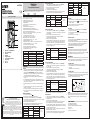
Descrizione dello strumento
MAX
E E
C
B
20 M
2M
20 0K
20 K
2K
PN P
10 A
20 0m A
20 mA
2m A
20 0
20 0
2V
20V
V
600V
1000V
CAT.
CAT.
FU SE D
MA X 10 A
10A
COM
DC 10 00V/0.2 A
DC 75 0V/0.2A
VΩA/ mA
Ω
OFF
BL CT R
HOLD
10 00 V
75 0V
20 0V
mV
20 0A
NP N/ LED
A
Ω
VE 502E
DC /A C
1.
4.
2.
5.
6.
7.
9.
3.
8.
1. Display LCD con retroilluminazione
2. Tasto retroilluminazione
3. Tasto Hold
4. Tasto AC/DC
5. Selettore di funzione
6. Socket per prove transistor/LED
7. Jack
VΩµA/mA
8. Jack 10A
9. Jack COM
Manuale d'uso
TESTER DIGITALE
Leggere attentamente tutte le istruzioni
Tester digitale per la misura di tensioni AC/DC, correnti AC/DC, resistenze, prova diodo, prova transistor, test di
continuità. E’ adatto per l’uso professionale sul campo in laboratorio e per uso domestico.
Codice Modello Descrizione
VE772600 VE 502E Tester digitale
CARATTERISTICHE TECNICHE
• Indicazione massima: 1999 (3 ½ digits)
• Lettura della misura: 2/3 volte ogni secondo
• Pulsante per attivazione funzione data hold
• Display retroilluminato
• Selettore rotativo a 20 posizioni per impostazione funzione
• Alta sensibilità: 100µV
• Impedenza: 100MΩ su tutti i range DCV e ACV
• Visualizzazione automatica fuori scala (visualizzazione “1” )
• Alimentazione: 1x6F22 (batteria 9V) con segnalazione batteria scarica
• Indicazione automatica della polarità per misure DC
• Indicazione sonora nel caso di misure fuori scala di tensioni, correnti, resistenze
• Prova diodo con corrente costante 1mA
• Prova transistor hFE con corrente di base 10µA
• Test di continuità con indicazione sonora sotto i 50 ohm
• Massima tensione di modo comune: 380V AC/DC rms
• Condizioni ottimali di funzionamento: 23°C ± 5°C. < 75% RH
• Temperatura di funzionamento: 0 ÷ 40 °C
• Umidità di funzionamento: < 80% RH fino a 31°C, decrescente fino al 50% RH a 40°C
• Condizioni di immagazzinamento: -10°C ÷ +50°C, <80% RH
• Peso e dimensioni: 240g circa, 74x145x40 mm
• Accessori in dotazione: manuale d’uso, puntali per test
• Categoria di isolamento (over voltage category): CAT II 1000V
• Grado di inquinamento: 2 (IEC-664)
FUNZIONE JACK UTILIZZATI SOVRACCARICO MASSIMO
V/DC V/OHM + COM 1000V DC
V/AC V/OHM + COM 750V rms. AC
OHM V/OHM + COM 380V DC/AC (Protetto)
A/DC, AC A + COM 0,5A 250V DC/AC
10A/DC, AC 10A + COM 10A 250V DC/AC
Diodo, continuità V/OHM + COM 380V DC/AC (Protetto)
hFE/LED Sockets dedicato 1000
FUNZIONAMENTO
Precauzioni
1. Controllare la carica della batteria spostando il selettore di funzione dalla posizione OFF
in qualsiasi altra posizione. Se la batteria è scarica, compare l’indicazione sul display: far
riferimento alla sezione MANUTENZIONE in questo manuale per la sostituzione
2. Il simbolo vicino le boccole indica di far attenzione a non superare i valori di tensione o
corrente stabiliti al fine di prevenire danneggiamenti al circuito interno
3. Posizione il selettore nella posizione relativa che si vuole misurare prima di effettuare
l’operazione
4. Se l’ordine di grandezza della tensione o della corrente che si deve misurare non è noto a
priori, posizionare il selettore nella scala più elevata ed eventualmente posizionare il selettore
su una scala inferiore successivamente
5. Se il display visualizza il simbolo “1” (over-range) posizionare il selettore su una scala più
alta
6. Non misurare correnti superiori a 10A per più di 15 secondi per prevenire rotture dello
strumento o pericoli per l’utente.
7. Per evitare scosse elettriche, disconnettere i puntali prima di rimuovere la cover posteriore
8. Per una protezione continua contro gli incendi, sostituire i fusibili solo con altri aventi le
stesse caratteristiche.
Misure di tensioni continue DC
1. Posizionare il selettore nella scala V
2. Assicurarsi che il tasto AC/DC sia in posizione DC (non premuto)
3. Collegare il puntale nero al jack “COM” e il puntale rosso al jack VΩµA/mA
e successivamente posizionare i puntali sull’elemento da testare. Se si conosce la polarità del
circuito da testare, collegare il puntale nero al polo (-).
4. Il valore della tensione è visualizzato sul display
Nota: non applicare più di 1000V indipendentemente dalla scala selezionata, in quanto
tensioni superiori potrebbero causare il danneggiamento del dispositivo.
SCALA PRECISIONE RISOLUZIONE PROTEZIONE SOVRACCARICO
200mV ± (0,5% of rdg. +1 digit) 100µV
DC 1000V
AC 750V rms.
2.000V
± (1,0% of rdg. +2 digits)
1mV
20.00V 10mV
200.0V 100mV
1000V ± (1,5% of rdg. +2 digits) 1V
Misure di tensioni alternate AC
1. Collegare il puntale nero al jack “COM” e il puntale rosso al jack VΩµA/mA
e successivamente posizionare i puntali sull’elemento da testare
2. Assicurarsi che il tasto AC/DC sia in posizione AC (premuto)
3. Posizionare il selettore nella scala V~
4. Il valore della tensione è visualizzato sul display
Nota: non applicare più di 300V sulla scala 200mV e 750V sulle altre scale in quanto
tensioni superiori potrebbero causare il danneggiamento del dispositivo.
SCALA PRECISIONE RISOLUZIONE PROTEZIONE SOVRACCARICO
200mV ± (1,0% of rdg. +3 digit) 100µV
DC 1000V
AC 750V rms.
2V
± (1,5% of rdg. +3 digits)
1mV
20V 10mV
200V 100mV
750V ± ( 2,5% of rdg. +4 digits) 1V
Range di frequenza: da 40Hz a 1000Hz
Misure di correnti continue DC
1. Collegare il puntale nero al jack “COM” e il puntale rosso al jack VΩµA/mA per
correnti fino a 400mA. Per correnti superiori e comunque fino a 10A, spostare il puntale
rosso sul jack “10A”
2. Assicurarsi che il tasto AC/DC sia in posizione DC (non premuto)
3. Posizionare il selettore nella scala delle correnti adeguata e successivamente
posizionare i puntali sull’elemento da testare
4. Il valore della corrente è visualizzato sul display
Nota: il valore massimo della corrente di ingresso è di 0,5A o 10A in funzione di quale
jack è utilizzato. Correnti eccessive rischierebbero di rovinare il fusibile di protezione,
che può comunque essere sostituito. Ci sono due fusibili diversi per la protezione del
circuito a 0,5A (0,5A) e quello a 10A (10A). La caduta di tensione massima sui terminali
è di 200 mA eccetto per la scala 10A.
SCALA PRECISIONE RISOLUZIONE
200µA
± (1,2% of rdg. +1 digit)
100nA
2mA 1µA
20mA 10µA
200mA 100µA
10A ± (2,0% of rdg. +3 digits) 10mA
Protezione sovracorrenti: con fusibile 0.5A/250V o fusibile 10A/250V
Misure di correnti alternate AC
1. Collegare il puntale nero al jack “COM” e il puntale rosso al jack VΩµA/mA per
correnti fino a 0,2A. Per correnti superiori e comunque fino a 10A, spostare il puntale
rosso sul jack “10A”
2. Assicurarsi che il tasto AC/DC sia in posizione AC (premuto)
3. Posizionare il selettore nella scala delle correnti adeguata e successivamente
posizionare i puntali sull’elemento da testare
4. Il valore della corrente è visualizzato sul display
Nota: il valore massimo della corrente di ingresso è di 0,2A o 10A in funzione di quale
jack è utilizzato. Correnti eccessive rischierebbero di rovinare il fusibile di protezione,
che può comunque essere sostituito. Ci sono due fusibili diversi per la protezione del
circuito a 0,5A (0,5A) e quello a 10A (10A). La caduta di tensione massima sui terminali
è di 200 mA eccetto per la scala 10A.
SCALA PRECISIONE RISOLUZIONE
200µA
± (1,5% of rdg. +3 digit)
100nA
2mA 1µA
20mA 10µA
200mA 100µA
10A ± (2,5% of rdg. +5 digits) 10mA
Protezione sovracorrenti: con fusibile 0,5A/250V o fusibile 10A/250V
Range di frequenza: da 40Hz a 1000Hz. Indicazione del valore medio dell'onda sinusoidale
Misure di resistenza
1. Collegare il puntale nero al jack “COM” e il puntale rosso al jack VΩµA/mA
2. Posizionare il selettore nella scala Ω adeguata e successivamente posizionare i puntali
sull’elemento da testare
3. Il valore della resistenza è visualizzato sul display
Nota 1: se il valore della resistenza da misurare è superiore alla scala impostata, sul
display compare l'indicazione 1. (over-range): selezionare una scala più alta.
Se la resistenza da misurare è superiore a 1 MOhm, potrebebro essere necessari alcuni
secondi affinchè il valore visualizzato sul display divenga stabile. Questo comportamento
è normale per valori di resistenza elevati
Nota 2: finchè i terminali non sono connessi sull’elemento da testare (circuito aperto), il
display visualizza la scritta 1. (over-range)
Nota 3: quando si effettuano misure di resistenza, assicurarsi che il circuito in esame
non sia in tensione e che i componenti capacitivi siano completamente scarichi
SCALA PRECISIONE RISOLUZIONE PROTEZIONE SOVRACCARICO CON PTC
200 ohm ± (1,2% of rdg. +2 digit) 0,1 ohm
MAX
DC/AC 380V rms.
2K ohm
± (1,0% of rdg. +2 digits)
1 ohm
20K ohm 10 ohm
200K ohm 100 ohm
2M ohm 1K ohm
20M ohm ± (2,5% of rdg. +4 digits) 10K ohm
Protezione da sovracarico tramite PTC: AC/DC 380V rms Max.
Test del diodo
1. Collegare il puntale nero al jack “COM” e il puntale rosso al jack VΩµA/mA
2. Posizionare il selettore in posizione e successivamente posizionare i puntali
sull’elemento da testare.
3. Il valore della tensione di lavoro del diodo è visualizzato sul display.
Protezione da sovratensione tramite PTC: 250V AC/DC rms
Test continuità
1. Collegare il puntale nero al jack “COM” e il puntale rosso al jack "VΩµA/mA"
2. Posizionare il selettore in posizione
3. Posizionare i puntali sull’elemento da testare: se la resistenza misurata è inferiore a
50Ω, il buzzer suona.
Protezione da sovratensione tramite PTC: 250V AC/DC rms
Test transistor hFE e LED
1. Posizionare il selettore nella posizione NPN/LED per test di transistor tipo NPN o LED,
in posizione PNP per test di transistor PNP
2. Determinare il tipo di transistor NPN o PNP ed individuare i terminali emettitore-base-
collettore. Inserire i pin del transistor nelle feritoie presenti sul frontale del dispositivo.
3. Il display visualizza il valore hFE. Condizioni dei test: 10µA VCE 2.8V.
4. Per il test dei LED, inserire i pin del LED nelle feritoie “E” e “C”
RETROILLUMINAZIONE
Il display del dispositivo è dotato di retroilluminazione per agevolare la lettura dei valori
misurati in condizione di scarsa illuminazione. Per attivare la retroilluminazione, tenere
premuto il tasto BLCTR per almeno 2 secondi (il selettore non deve essere in posizione OFF).
La retroilluminazione si spegne automaticamente trascorsi 10 secondi.
MANUTENZIONE
Attenzione: prima di procedere con la sostituzione della batteria e dei fusibili di protezione
rimuovere i puntali e posizionare il selettore in posizione OFF
Per sostituire la batteria
1. Svitare le viti poste sul retro del dispositivo e rimuovere la cover posteriore.
2. Sostituire la batteria esausta con una nuova avente le stesse caratteristiche
9 Volt tipo 6F22.
3. Riposizionare la cover posteriore e avvitare le viti
Per sostituire i fusibili
1. Se il dispositivo non misura i valori di corrente, controllare che il fusibile di protezione non
sia danneggiato. In questo caso, sostituire il fusibile in questione con uno di tipo equivalente.
2. Sono presenti due tipi di fusibile a seconda del circuito da proteggere:
0,5A/250V (per scala mA) o 10A/250V (per scala 10A)
PULIZIA
Per pulire il dispositivo usare un panno umido dopo averlo spento ed aver tolto i puntali.
Non usare liquidi, solventi o altri prodotti che possano ridurre il livello di sicurezza del
dispositivo.
NORME DI RIFERIMENTO
La conformità alle Direttive Comunitarie:
2014/35/UE (LVD), 2014/30/UE (E.M.C.D.)
è dichiarata con riferimento alle seguenti Norme armonizzate:
• CEI EN 61010-1
• CEI EN 61010-031
• CEI EN 61326-1, CEI EN 61326-2-2
0.5A/250v
10A/250v
ai sensi dell’art. 26 del Decreto Legislativo 14 marzo 2014, n. 49
“Attuazione della direttiva 2012/19/UE
sui rifiuti di apparecchiature elettriche ed elettroniche (RAEE)”
Il simbolo del cassonetto barrato riportato sull’apparecchiatura o sulla sua
confezione indica che il prodotto alla fine della propria vita utile deve essere raccolto
separatamente dagli altri rifiuti. L’utente dovrà, pertanto, conferire l’apparecchiatura
giunta a fine vita agli idonei centri comunali di raccolta differenziata dei rifiuti
elettrotecnici ed elettronici.
In alternativa alla gestione autonoma è possibile consegnare l’apparecchiatura che si desidera
smaltire al rivenditore, al momento dell’acquisto di una nuova apparecchiatura di tipo equivalente.
Presso i rivenditori di prodotti elettronici con superficie di vendita di almeno 400 m2 è inoltre possibile
consegnare gratuitamente, senza obbligo di acquisto, i prodotti elettronici da smaltire con dimensioni
inferiori a 25 cm.
L’adeguata raccolta differenziata per l’avvio successivo dell’apparecchiatura dismessa al riciclaggio,
al trattamento e allo smaltimento ambientalmente compatibile contribuisce ad evitare possibili effetti
negativi sull’ambiente e sulla salute e favorisce il reimpiego e/o riciclo dei materiali di cui è composta
l’apparecchiatura.

ISCOM070-1809
Mod. VE 502E
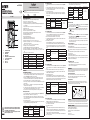
Description
MAX
E E
C
B
20 M
2M
20 0K
20K
2K
PN P
10 A
20 0m A
20 mA
2m A
20 0
20 0
2V
20V
V
600V
10 00V
CAT.
CAT.
FU SE D
MA X 10 A
10A
COM
DC 10 00V/0.2 A
DC 75 0V/0.2A
VΩA/ mA
Ω
OFF
BL CT R
HOLD
10 00 V
75 0V
20 0V
mV
200A
NP N/ LED
A
Ω
VE 502E
DC /A C
1.
4.
2.
5.
6.
7.
9.
3.
8.
1. Backlit LCD Display
2. Backlit Button
3. Hold Button
4. AC/DC Button
5. Rotary Switch For Function Selection
6. Socket For Test Transistor
7. Jack
VΩµA/mA
8. Jack 10A
9. Jack COM
User Manual
DIGITAL TESTER
Read all the instructions carefully
Digital tester for measurement of: AC/DC voltage, AC/DC current, resistance, diode test, transistor 2 LED test,
continuity test.
It is designed for the professional at work in the field or laboratory and for in-door use.
Code Model Description
VE772600 VE 502E Digital tester
GENERAL CHARACTERISTICS
• Maximum Indication: 1999 counts (3 1/2 digits) with large LCD display.
• Accuracies are ± (% reading + No. of digits)
• Sampling rate: 2-3 times reading per second (approximate).
• Push-type Switch buttons respectively for Data Hold-on(HOLD), Back-lighting(BLCTR) and AC/
DC (Interchange.)
• Single 20 positions easy to use rotary switch for Ten Functions and Range selection.
• High sensitivity of 100µV.
• Impedance: 10MΩ on all DCV & ACV Ranges.
• Automatic over-range indication with the “1” displayed.
• Automatic low battery power (6.4V) indication with the battery symbol "LOBAT".
• Automatic polarity indication on DC ranges.
• Diode testing with 1mA fixed current.
• Transistor hFE Test With ib-10µA.
• Continuity Test by beeper sounding below 50 ohm.
• Maximum common mode voltage: 380V DC/AC rms.
• Environment for guaranteed accuracy: 23°C±5°C, less than 75% RH.
• Temperature Scope: Operating 0°C to 40°C, 32 °F to 104 °F. Max. RH 80% to 31°C
decreasing linear to 50% RH at 40°C.
• Storage: -10 °C to 50°C, 14 °F to 122 °F at < 80% relative humidity.
• Power Supply: One 6F22 9-volt battery or equivalent.
• Size & Weight: 74(W) x 145(D) x 40(D) mm and 240g (including battery).
• Accessories: Operating manual, 1 Set of test leads with 20AWG 1000V Class PVC Wire.
• This instrument complies with insulation category (over voltage category), CAT II 1000V, CAT III
600V.
• Pollution degree 2 in accordance with IEC-664
Function Test Leads connected Overload Maximum
V/DC V/OHM + COM 1000V DC
V/AC V/OHM + COM 750V rms. AC
OHM V/OHM + COM 380V DC/AC Protected
A/DC, AC A + COM 0.5A 250V DC/AC
10A/DC, AC 10A + COM 10A 250V DC/AC
Diode, Buzz V/OHM + COM 380V DC/AC Protected
hFE/LED Special Transistor Sockets 1000
OPERATIONS
SAFETY WARNINGS AND CAUTIONS
1. Check the 9-volt battery by setting the range switch to any other range but Off. If the battery
is weak a sign will appear on the display. If this does not appear on the display proceed as
below. See MAINTENANCE if the battery has to be replaced.
2. The mark or sign next to the test lead jacks warns that the input voltage or current
should not exceed the indicated values. This is to prevent damage to the internal circuit.
3. The function switch should be set to the range to be tested before operation.
4. If the voltage or current range is not known beforehand set the RANGE switch to a high range
and work down.
5. When only the figure “ 1” is displayed, over-range is being indicated, and the FUNCTION
switch must be set to a higher range.
6. Do not measure large current 10 amp lasting more than 15 seconds. This can cause damage
to the instrument and or equipment being tested and or injury to the user.
7. To avoid electric shock, disconnect measuring terminals before removing back cover.
DC Voltage Measurement
1. Connect the BLACK test lead to the COM jack and the RED test lead to the VΩµA/mA jack.
2. Make sure that the AC/DC switch Button is on DC position (UP).
3. Set the FUNCTION switch to the V range to be used and connect the test leads across the
source or load under measurement. The polarity of the RED lead connection will be indicated
at the same as the voltage.
4. Get the readings from the LCD.
Note: Do not apply more than 1000V at all ranges to the input. Indication is possible at higher
voltages, but there is danger of damaging the internal circuit.
Range Accuracy Resolution Over load Protection
200mV ± (0.5% of rdg. +1 digit) 100µV
DC 1000V
AC 750V rms.
2.000V
± (1.0% of rdg. +2 digits)
1mV
20.00V 10mV
200.0V 100mV
1000V ± (1.5% of rdg. +2 digits) 1V
AC Voltage Measurement
1. Connect the BLACK test lead to the COM jack and the RED test lead to the VΩµA/mA
jack.
2. Push down the AC/DC switch Button. Then all the ranges of voltage are AC type.
3. Set the FUNCTION switch to the V range to be used and connect the test leads across
the source or load under measurement.
4. Get the readings from the LCD.
Note: Do not apply more than 300V at 200mV range and 750V rms. at other ranges to
the input. Indication is possible at higher voltages, but there is danger of damaging the
internal circuitry.
Range Accuracy Resolution Over load Protection
200mV ± (1.0% of rdg. +3 digit) 100µV
DC 1000V
AC 750V rms.
2V
± (1.5% of rdg. +3 digits)
1mV
20V 10mV
200V 100mV
750V ± ( 2.5% of rdg. +4 digits) 1V
Frequency Range: 40Hz to 1000Hz
DC Current Measurement
1. Connect the BLACK test lead to the COM jack and the RED test lead to the VΩµA/mA
jack for Current Maximum of 400mA (Note: The polarity of the RED test lead is “+”).
For a maximum of 10A, move the red test lead to the 10A jack.
2. Make sure that the AC/DC switch Button is on DC position(UP)
3. Set the FUNCTION switch to the A range to be used and connect the test leads in series
with the load under measurement.
4. Get the readings from the LCD.
Note: A. The Maximum input current is 0.5A or 10A depending on the jack used.
Excessive current will blow the fuse that must be replaced. Another fuse 10A protects
the 10A range. The fuse rating should be 0.5A or no more than 10A to prevent damage
to the internal circuit. The Maximum terminal voltage drop is 200mV except for the 10A
range.
Range Accuracy Resolution
200µA
± (1.2% of rdg. +1 digit)
100nA
2mA 1µA
20mA 10µA
200mA 100µA
10A ± (2.0% of rdg. +3 digits) 10mA
Overload Protection: Diode & 0.5A/250V Fuse of ordinary glass tube type but 10A range with 10A/250V
fuse of ordinary glass tube type.
AC Current Measurement
1. Connect the BLACK test lead to the COM jack and the RED test lead to the VΩµA/mA
jack for a maximum of 0.2A. For a maximum of 10A, Move the RED test lead to the 10A
jack.
2. Push down the AC/DC switch Button. Then all the ranges of current are AC type.
3. Set the FUNCTION switch to the A range to be used and connect the test lead in series
with the load under measurement.
4. Get the readings from the LCD.
Note: A. The Maximum input current is 0.2A or 10A depending upon the jack used.
Excessive current can blow the fuse. Another fuse 10A protects the 10A Range. The fuse
rating should be 0.5A or no more than 10A to prevent damage to the internal circuit. The
maximum terminal voltage drop is 200mV except for the 10A range.
Range Accuracy Resolution
200µA
± (1.5% of rdg. +3 digit)
100nA
2mA 1µA
20mA 10µA
200mA 100µA
10A ± (2.5% of rdg. +5 digits) 10mA
Overload Protection: Diode & 0.5A/250V Fuse of ordinary glass tube type, but 10A range with 10A/250V
fuse of ordinary glass tube type. Frequency Range: 40Hz to 1000Hz. Indication: Average (rms. of sine
wave).
Resistance Measurement
1. Connect the BLACK test lead to the COM j jack and the RED test lead to the VΩµA/
mA jack (Note: The polarity of the RED test lead is “+”)
2. Set the FUNCTION switch to the Ω range to be used and connect the test leads across
the resistance under measurement.
3. Get the readings from the LCD.
Note:
1. If the resistance value being measured exceeds the maximum value of the range
selected, an over-range indication will be displayed (“1”), then select a higher range.
For resistance of approximate 1M ohm and above the Meter may take a few seconds to
become stable. This is normal for high resistance readings.
2. When the input is not connected i.e. at open circuit the figure “1” will be displayed for
the over-range condition.
3. When checking in-circuit resistance, be sure the circuit under test has all power
removed and that all capacitors are fully discharged.
Range Accuracy Resolution Overload Protection by PTC
200 ohm ± (1.2% of rdg. +2 digit) 0.1 ohm
MAX
DC/AC 380V rms.
2K ohm
± (1.0% of rdg. +2 digits)
1 ohm
20K ohm 10 ohm
200K ohm 100 ohm
2M ohm 1K ohm
20M ohm ± (2.5% of rdg. +4 digits) 10K ohm
Overload Protection by PTC: Max. AC/DC 380V rms.
Diode Measurement
1. Connect the BLACK test lead to the COM jack and the RED test lead to the VΩµA/mA
jack. (Note: The polarity of the RED test lead is “+”)
2. Set the FUNCTION switch to the range and connect the test leads across the
diode under measurement. Display shows the approximate forward working voltage of
this . Overload protection by PTC against high Voltage across Max. DC/AC 380V
rms. at this Diode range.
Continuity Test
1. Connect the BLACK test lead to the COM jack and the RED test lead to the VΩµA/mA
2. Set the FUNCTION switch to the D range and the LCD will show the
approximate resistance of the circuit.
3. Connect the test leads to two points of circuit. If the resistance is lower than approx. 50
ohm, the buzzer sounds. Overload protection by PTC against high Voltage across Max.
DC/AC 380V rms. at this range.
Transistor hFE & LED Test
1. Set the Range switch to the "NPN/LED" to measurement LED or NPN transistor, to NPN to
measurement PNP transistor.
2. Determine whether the transistor is NPN or PNP and locate the Emitter, Base and
collector terminals. Insert the pins into the proper holes of the special socket on the front
panel.
3. The display will read the approximate hFE Value at the test condition Base
Current 10µ. VCE 2.8V.
4. Get the readings from the LCD.
5. For LED test, firstly set the Range switch to the “NPN” range, and then directly insert the
two poles of LED separately into the “E” & “C” jacks of the special hFE input sockets on the
front panel. A normal LED will be bright.
Back Lighting Operation
1. Set the Range switch to any range but OFF.
2. Push the BLCTR button two seconds, and the LCD will be lit for easy reading
3. After 10 seconds, the light will turn off.
MAINTENANCE
Replacement for Batteries and/or Fuse should only be done after the test leads have been
disconnected and POWER OFF.
9-Volt Battery Replacement
Remove the screws from the back case of the meter, and lift off the rear case.
Remove the worn battery and replace with a new 9-volt 6F22 battery or equivalent.
Close the back case and tighten the screws.
Fuse Replacement
When current measurements are impossible, check if overload protection fuse blown.
There are two kinds of fuses. When the fuses need replacement, use only 0.5A/250V or
10A/250V fuses identical in physical size to the original.
CLEANING
To clean the device, use a damp cloth after having turned it off and removing the leads.
Do not use liquids, solvents or other products that can reduce the safety level of the device.
REFERENCE STANDARDS
Compliance with Community Directives:
2014/35/EU (LVD), 2014/30/EU (E.M.C.D.)
is declared in reference to the harmonized Standards
• EN 61010-1
• EN 61010-031
• EN 61326-1, EN 61326-2-2
0.5A/250v
10A/250v
This symbol on the product and/or accompanying documents
means that used electrical and electronic products should not
be mixed with general household waste.
For proper treatment, recovery and recycling, please take this
product to designated collection.
-
 1
1
-
 2
2


in altre lingue
- English: Vemer VE 502E User manual
Documenti correlati
Altri documenti
-
Ferm MMM1008 Manuale del proprietario
-
 Valex 1800160 Manuale del proprietario
-
Velleman DVM205AM Manuale utente
-
-
 Valex 1800161 Manuale del proprietario
-
TACKLIFE DM02A Manuale del proprietario
-
Beta 1760B Istruzioni per l'uso
-
-
-

