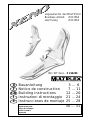
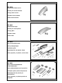
MULTIPLEX Xeno Building Instructions
- Categoria
- Giocattoli
- Tipo
- Building Instructions

1
BK / KIT Xeno # 214239
vorgesehen für den MULTIPLEX
Brushless-Antrieb # 33 2654
oder Tuning # 33 2655
F
GB
D
E
I
Bauanleitung 3 ... 6
Notice de construction 7 ... 11
Building instructions 12 ... 20
Instruzioni di montaggio 21 ... 24
Instrucciones de montaje 25 ... 28
Ersatzteile
Replacement parts
Pièces de rechanges
Parti di ricambio
Repuestos
30 ... 31
© Copyright by MULTIPLEX 2009 Version 1.0

2
D
F
GB
I
E
Sicherheitshinweise
Prüfen Sie vor jedem Start den festen Sitz des Motors und der Luftschraube - insbesondere nach dem Transport, härteren Landungen
sowie Abstürzen. Prüfen Sie ebenfalls vor jedem Start den festen Sitz und die richtige Position der Tragflächen.
Akku erst einstecken, wenn Ihr Sender eingeschaltet ist und Sie sicher sind, dass das Bedienelement für die Motorsteuerung auf "AUS"
steht.
Im startbereiten Zustand nicht in den Bereich der Luftschraube greifen.
Vorsicht in der Luftschraubendrehebene - auch Zuschauer zur Seite bitten!
Zwischen den Flügen die Motortemperatur durch vorsichtige Fingerprobe prüfen und
vor einem Neustart den Motor ausreichend abkühlen lassen. Die Temperatur ist richtig, wenn Sie den Motor problemlos berühren
können. Insbesondere bei hohen Außentemperaturen kann dieses bis zu 15 Minuten dauern.
Denken Sie immer daran: Niemals auf Personen und Tiere zufliegen.
Conseils de sécurité
Avant chaque décollage, vérifiez la fixation du moteur et de l'hélice, notamment après le transport, après les atterrissages violents et
après un “Crash”. Vérifiez également, avant chaque décollage la fixation ainsi que le positionnement de l’aile.
Ne branchez l’accu de propulsion que si vous êtes sûr que votre émetteur est allumé et que l’élément de commande moteur est en
position “ARRET”.
Ne mettez pas vos doigts dans l’hélice! Attention à la mise en marche, demandez également aux spectateurs de reculer.
Entre deux vols, vérifiez en posant un doigt dessus, la température du moteur, laissezle refroidir suffisamment avant le prochain
décollage. La température est correcte si vous pouvez maintenir votre doigt ou votre main sur le moteur. Le temps de refroidissement
peut varier jusqu’à 15 minutes s’il fait particulièrement chaud.
Pensez-y toujours: ne volez jamais vers ou au-dessus des personnes ou des animaux.
Safety notes
Before every flight check that the motor and propeller are in place and secure - especially after transporting the model, and after hard
landings and crashes. Check also that the wing is correctly located and firmly secured before each flight.
Don’t plug in the battery until you have switched on the transmitter, and you are sure that the motor control on the transmitter is set to
“OFF”.
When the model is switched on, ready to fly, take care not to touch the propeller. Keep well clear of the propeller disc too, and ask
spectators to stay back.
Allow the motor to cool down after each flight. You can check this by carefully touching the motor case with your finger. The
temperature is correct when you can hold your finger on the case without any problem. On hot days this may take up to 15 minutes.
Please keep in mind at all times: don’t fly towards people or animals.
Note di sicurezza
Prima di ogni decollo controllare che il motore e la eliche siano fissati stabilmente - specialmente dopo il trasporto, atterraggi duri e se il
modello è precipitato. Controllare prima del decollo anche il fissaggio e la posizione corretta delle ali.
Collegare la batteria solo quando la radio è inserita ed il comando del motore è sicuramente in posizione ”SPENTO”.
Prima del decollo non avvicinarsi al campo di rotazione della eliche. Attenzione alla eliche in movimento - pregare che eventuali spettatori
si portino alla dovuta distanza di sicurezza!
Tra un volo e l’altro controllare cautamente con le dita la temperatura del motore e farli raffreddare sufficientemente prima di ogni nuovo
decollo. La temperatura è giusta se si possono toccare senza problemi. Specialmente con una temperatura esterna alta questo può
durare fino a 15 minuti.
Fare attenzione: Non volare mai nella direzione di persone ed animali.
Advertencias de seguridad
Compruebe antes de cada despegue que el motor y la hélice estén fuertemente sujetados, sobretodo después de haberlo transportado,
de aterrizajes más fuertes así como después de una caída. Compruebe igualmente antes de cada despegue que las alas estén bien
sujetas y bien colocadas.
Conectar la batería, cuando la emisora esté encendida y Usted esté seguro que el elemento de mando para el motor esté en ”OFF”.
No meter la mano en la zona inmediata a la hélice cuando el avión esté a punto de despegar. ¡Cuidado con la zona de la hélice! ¡Pedir a
los espectadores que se aparten!
Entre los vuelos hay que comprobar cuidadosamente la temperatura del motor con el dedo y dejar que el motor se enfríe antes de volver
a despegar. La temperatura es correcta, si puede tocar el motor sin problemas. Sobretodo en el caso de temperaturas del ambiente muy
altas, esto puede tardar unos 15 minutos.
Recuerde: No volar nunca hacía personas o animales.

12
# 21 4239
Examine your kit carefully!
MULTIPLEX model kits are subject to constant quality checks throughout the production process, and we sincerely hope that you are
completely satisfied with the contents of your kit. However, we do ask you to check all the parts (referring to the Parts List) before you
start construction, as we cannot exchange components which you have already modified. If you find any part is not acceptable, we
will readily correct or exchange it once we have examined it. Just send the component, with adequate postage pre-paid, to our Model
Department; please be sure to include the purchase receipt and the returns form (included in the kit) completed in full. We are
constantly working on improving our models, and for this reason we must reserve the right to change the kit contents in terms of
shape or dimensions of parts, technology, materials and fittings, without prior notification. Please understand that we cannot
entertain claims against us if the kit contents do not agree in every respect with the instructions and the illustrations.
Caution!
Radio-controlled models, and especially model aircraft, are by no means playthings. Building and operating them safely
requires a certain level of technical competence and manual skill, together with discipline and a responsible attitude at the
flying field. Errors and carelessness in building and flying the model can result in serious personal injury and damage to
property. Since we, as manufacturers, have no control over the construction, maintenance and operation of our products, we
are obliged to take this opportunity to point out these hazards and to emphasise your personal responsibility.
Additional items required for the “Xeno”:
MULTIPLEX radio control components for the Xeno:
RX-6-SYNTH IPD receiver 35 MHz A / B- band Order No. 5 5876
alternatively: 40 / 41 MHz Order No. 5 5877
or MULTIPLEX RX-7-DR light M-Link 2.4 GHz Order No. 5 5810
Tiny MG servo, two required (2 x elevon) Order No. 6 5122
Battery charger:
MULTIcharger LN-3008 EQU Order No. 9 2540
for LiPo, LiIo and LiFe batteries, 2S to 3S, and
NiMH / NiCd batteries with 4 to 8 cells
Xeno power set Order No. 33 2654
Contents:
Himax 2212-1180 motor, BL-20 S-BEC speed controller, 8 x 5”
folding propeller, taper collet, driver and 35 mm Ø spinner, canopy,
motor fairing, CFRP extension shaft, plastic parts, small items
Xeno TUNING power set Order No. 33 2655
Contents:
Himax 2816-1220 motor, BL-30 S-BEC speed controller, 9 x 6”
folding propeller, taper collet, driver and 35 mm Ø spinner, canopy,
motor fairing, CFRP extension shaft, plastic parts, small items
Flight battery: Li-BATT BX 3/1-950 Order No. 15 7118
Receiver battery, glider version: 4 AA cells, S or W format Not in MPX range
Tools:
Scissors, balsa knife
Note: please remove the illustration pages from the centre of the instructions.
Specification:
Wingspan: 1245 mm
All-up weight, glider, approx.: 550 g
All-up weight, electric, approx.: 650 / 690 g Standard / Tuning
Wing area: 32 dm²
Wing loading min.: 17.2 g/dm² glider, 2.03 g/dm² electric,
21.5 g/dm² electric (Tuning version)
RC functions: Aileron, elevator (delta mixer), throttle
GB

13
Like every aircraft, the airframe strength of the Xeno has its limits. Extreme dives and senselessly violent manoeuvres can
result in the loss of the model. Please note: in such cases we are not prepared to exchange the model. We urge you to fly gently
at first, and work your way gradually towards the aeroplane’s limits. The Xeno is designed to accept our Tuning (upgrade)
power set, but is only capable of withstanding the loads on the airframe if built exactly according to the instructions, and if
flown in an undamaged state.
Please note: the model is subjected to the most severe loads when dived with the propeller folded.
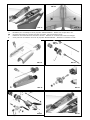
Glue the fin holders 26 to the left and right fins; note that the fins
are identical. As you will already have noticed, the fins are very
easily removed for transport.
Fig. 09
Install the swivel pushrod connectors 12, 13, 14 and 15 in the
outermost hole in the elevon horns 30. Glue the horns 30 in the
elevons (elevon = combination of elevator and aileron). The row
of holes must face the servo.
Fig. 10
5. Installing the servos
The model is designed for MULTIPLEX Tiny MG servos. These
are robust metal-geared servos at a reasonable price; they have
been tested in the model, and are strongly recommended. You
will also find that the servo leads are the correct length as
standard. If you prefer to use different servos, you may need to
adjust the installation wells and purchase extension leads.
Fit the servos and glue them in place with a drop of Zacki ELAPOR
at each mounting lug. Deploy the servo leads along the cable
duct, and route the connectors into the internal space in the
fuselage cradle. Seal the cable wells with adhesive film.
Fig. 11
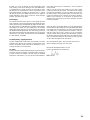
6. Elevon pushrods
Connect the Z-bend of the elevon pushrods 40 to the outermost
hole in the servo output arms (approx. 12.5 mm from the hinge
pivot axis). Set the servo output arms at right-angles to the servo
case, and connect the pushrods to the swivel connectors
mounted on the elevon horns. Tighten the clamping screws,
and secure the nuts and screws with a drop of thread-lock fluid
or glue.
Release the elevons at both ends! Fig. 12
7. Servo fairings
The final step in this stage is to install the servo fairings 31 + 32.
The fairings are simply glued in place with one or two drops of
cyano glue, as they can easily be removed again at any time if
required.
Fig. 13
8. Preparing the canopies
Attach the canopy latches 24 + 25 to the canopy (glider canopy
23 and / or the power canopy - included in the Power Set). Glue
the latches in place with a little cyano.
Figs. 14 + 15
Important note
This model is not made of styrofoam™, and it is not possible to glue the material using white glue, polyurethane or epoxy;
these adhesives only produce a superficial bond which simply gives way when stressed. Please use medium-viscosity
cyano-acrylate glue exclusively, preferably our Zacki-ELAPOR®, # 59 2727 - the cyano glue optimised specifically for
ELAPOR® particle foam. At some points you will also need the extremely low-viscosity version of the adhesive: Zacki
ELAPOR super liquid, # 59 2728.
If you use Zacki-ELAPOR® you will find that you do not need cyano kicker or activator for most joints. However, if you
wish to use a different adhesive, and are therefore obliged to use kicker / activator spray, we recommend that you apply
the material in the open air to avoid health problems.
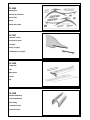
1. Before assembling the model
Please check the contents of your kit before you start working on
it.
You will find Figs. 01 + 02 helpful here, along with the Parts List.
2. Preparing the fuselage cradle
Apply Zacki ELAPOR to the hinge leaves 22, and push them fully
into the slots in both fuselage cradle shells 20 and 21. See Fig.
03
3. Trimming and joining the fuselage cradle
The wing panels fit inside the root ribs of the fuselage cradle
shells 20 + 21; you may find it necessary to compress the Elapor
foam slightly with your fingers to produce a neat fit. Check very
carefully dry - without glue - that everything fits as it should.
Fig. 04
Remove the cradle shells from the wings again.
Fit the hinge pin 41 through the hinge leaves. Apply Zacki
Elapor to the root face of both wings panels, then push the
wings together firmly and briskly, pressing them fully home
into the root ribs of the cradle. Check immediately that the
foam parts line up correctly with the plastic parts, and ensure
that there are no gaps along the joint lines - especially at the
nose. Leave the glued joints to cure completely before
resuming work on the model.
Fig. 05
This stage is completed by carefully running Zacki Elapor su-
per liquid along the edges between the fuselage cradle 20 +
21 and the foam, flexing the foam away from the plastic slightly
to allow the glue to penetrate. Allow the glue to set hard, then
withdraw the hinge pin 41 again before proceeding.
4. Completing the wings
- All joints should be completed using Zacki ELAPOR.
Trial-fit the spars 42 in the slots in the underside of both wing
panels. When you are satisfied, glue them in place, taking
care to apply adhesive along their full length. Wipe away
excess glue immediately.
Fig. 06
Glue the left and right fin supports 28 and 29 in the recesses
in the underside of both wings.
Fig. 07
Position the fin retaining clips 27 carefully, and glue them in
the recesses.
Fig. 08

14
9. Assembling the model
Push the hinge pin 41 through the hinge leaves, holding the rod
in a pair of pliers if necessary. Fit the fins 5 and allow them to
snap into the retaining clips. Check the wing folding mechanism.
Ensure that the canopy latch system works properly, and make
any minor adjustments required.
Fig. 16
10. Installing the radio control system
There are two different versions here: glider and electric glider /
glider
a. Glider:
This version requires a receiver battery consisting of four AA-
size NiMH cells in the S or W format. The battery should be
secured with Velcro (hook-and-loop) tape. The Centre of Gravity
can be adjusted within certain limits by re-positioning the battery.
If that is not sufficient, you will need to add a little lead ballast.
Ensure that the receiver battery does not obstruct the canopy
latches 24 + 25 when you try to engage them.
There is space for the receiver in the rear part of the fuselage
cradle. Deploy the aerial in the appropriate channel in the wing.
If you are using 2.4 GHz equipment, there is adequate space for
the aerials towards the front.
Fig. 17
b. Electric glider with glider option:
The flight battery (Li-Batt BX 3/1 - 950, # 15 7118) should be
installed in the front part of the fuselage cradle 20 + 21, where it
is retained with Velcro tape. The Centre of Gravity can be adjusted
within certain limits by re-positioning the battery. If that is not
sufficient, you will need to add a little lead ballast. Ensure that
the receiver battery does not obstruct the canopy latches 24 + 25
when you try to engage them.
The receiver can be located adjacent to the motor, with the aerial
deployed in the appropriate channel in the wing. Install the speed
controller next to the flight battery. If you detect interference when
you carry out a range-check, try swapping the positions of the
speed controller and the receiver.
The electric glider is designed to be powered by our Power Set,
# 33 2654 (45° climb performance) or the Tuning Set, # 33 2655
(vertical climb). These power sets contain everything you need,
but neither is included in the kit. Installing the power system in
the model takes just a few seconds: fold the model apart in the
centre, place the power set inside, fold it closed again, insert the
connector, and the model is ready for launch as a powered
glider.
Fig. 18
If you wish to fly the Xeno electric glider at the slope as a pure
glider, the conversion is carried out as follows:
Open the model, disconnect the motor plug, remove the power
set, fold the model closed again and fit the glider canopy: job
done, time to go gliding. As with the electric version, the flight
battery is used to power the receiver and servos via the speed
controller’s BEC system. No re-trimming is required, as the
power set is located virtually at the Centre of Gravity.
Fig. 19
11. Completing the power set
Assemble the power set, referring to the instructions supplied
with it.
Figs. A1 - A6
12. Initial test-run
We assume that all the radio control system components have
been installed and connected as shown in Figs. 17 and 18. Use
the Velcro tape 10 + 11 to secure the components.
Check the neutral position and the travels of the elevons. Check
that the servos rotate in the correct direction relative to the stick
movements, and ensure that the elevons are free-moving. Check
the direction of rotation of the motor, and reverse it if necessary.
13. Settings (guideline only!):
Centre of Gravity: approx. 220 mm (+/- 10 mm)
aft of the fuselage nose
Motor thrustline: pre-set
Fig. 20
Control surface travels:
Measured at the widest point of the elevons
Elevons
Aileron travel: 14 mm up / 16 mm down
Elevator travel: 12 mm up / 12 mm down
14. Test-flying:
For the first flight wait for a day with as little breeze as possible.
The early evening is often a good time.
If you are a beginner to model flying we strongly recommend that
you ask an experienced model pilot to help you for the first few
flights, as learning to fly alone is very rarely successful. If you
don’t know any other modellers, ask your local model shop about
flying clubs in the area, and go along to their flying site for help.
Another useful aid for those “first difficult steps” is a flight simulator
on a PC.
You can download a free simulator from the MULTIPLEX website
at www.multiplex-rc.de. An interface lead for your MPX
transmitter can be obtained from any model shop (Order No. # 8
5153).
Be sure to carry out a range-check before the first flight!
Just before the flight, charge up the transmitter battery and the
flight pack using the recommended procedures. Before you
switch on the transmitter, ensure that “your” channel is not already
in use.
Ask your assistant to walk away from the model, holding the
transmitter. The transmitter aerial should be fitted but completely
collapsed.
Your assistant should operate one of the functions constantly
while you watch the servos. The non-controlled servo should
stay motionless up to a range of about 60 m, while the controlled
one should follow the stick movements smoothly and without
any delay. Please note that this check can only give reliable results
if the radio band is clear of interference, and if no other radio
control transmitters are in use - even on different channels. If the
range check is successful, repeat it with the motor running.
There should be no more than a very slight reduction in effective
radio range with the motor turning.
If you are not sure about anything, please don’t risk a flight. Send
the whole system (including battery, switch harness and servos)
to the Service Department of your RC system manufacturer and
ask them to check it.
The first flight ...
Glider:
A hand-launch directly into any breeze, with the wings level and
the nose slightly down, will give you an initial idea whether the
model is correctly trimmed, or whether adjustments are required.
Flying at the slope
Ridge soaring is an extremely attractive form of model flying.
Soaring for hours on end in slope lift, or flying continuous
aerobatics, without needing any outside aid for launching, must
be one of the finest of all modelling experiences.

15
11
7 x 22
20
26
27
42
3
5
Abb. 01
Abb. 02
21
4
10
13
12
21
32
40
30
41
28
31
16
2
29
14
15
23
24
25

16
20
Abb. 03
Abb. 04
Abb. 05
Abb. 06
Abb. 07
3
Abb. 08
Abb. 09
26
Abb. 10
5
4
4
30
21
-
21
12
21
7 x 22
3
42
29
28
27
27
27
14
1315
4

17
Abb. 11
Abb. 12
Abb. 13
Abb. 14
Abb. 15
Abb. 16
Abb. 17
3
23
Abb. 18
3
4
3
4
32
-
4
1mm
1mm
23
25
24
25
24
21
25
20
41
RX
Akku
ESC
Akku
RX
40
Im Antriebssatz enthalten
Included in the power set

18
Abb. 19
Abb. 20
Abb. A1 Abb. A2
Abb. A3
Abb. A4
Abb. A5
Abb. A6
220 mm
D - Übersicht für den Zusammenbau der Antriebssätze # 332654+ # 332655 - Material nicht im Baukasten enthalten!
F - Illustrations pour l’assemblage du kit de propulsion #332654+#332655 – Matériel non compris dans le kit !
GB -
Overview of the power set assembly, # 33 2654 / # 33 2655 - parts not included in the kit!
I - Installazione dei set motorizzazione # 33 2654 / 33 2655 – Materiale non contenuto nella scatola di montaggio!
E - Visión general de la instalación de los kits de propulsión #332654 #332655 – ¡Materiales no incluidos en el kit!

19
But take care - there are dangers for your model lurking at the
slope. Firstly, in most cases landing is much more difficult than
at a flat field site. It is usually necessary to land in the lee of the
hill where the air is turbulent; this calls for concentration and a
high-speed approach. A landing on the slope face, i.e. right in
the slope lift, is even more difficult. Here the trick is to approach
slightly downwind, up the slope, and flare at exactly the right
moment, just before touch-down.
Electric flying
The electric-powered version gives you the highest possible
level of autonomy. The model should be launched with the motor
turning, but not running at full-throttle; this applies in particular to
the Tuning version. At a flat field site one battery charge will give
about eight to ten climbs to a good height prior to an extended
gliding phase. At the slope you can use the motor to guard against
the dreaded downdraught (sudden loss of lift, forcing you to land
the model at the foot of the hill). But aerobatics are also great fun
with the Xeno: rolls, inside and outside loops and inverted flight
are well within its capabilities.
15. Gilding the lily - applying the decals
The kit is supplied with a multi-colour decal sheet 2. Cut out the
individual name placards and emblems and apply them to the
model in the position shown in the kit box illustration, or in an
arrangement which you find pleasing.
16. Safety
Safety is the First Commandment when flying any model aircraft.
Third party insurance should be considered a basic essential. If
you join a model club suitable cover will usually be available
through the organisation. It is your personal responsibility to
ensure that your insurance is adequate (i.e. cover for powered
model aircraft).
Make it your job to keep your models and your radio control
system in perfect order at all times. Check the correct charging
procedure for the batteries you are using. Make use of all sensi-
ble safety systems and precautions which are advised for your
system. An excellent source of practical accessories is the MUL-
TIPLEX main catalogue, as our products are designed and
manufactured exclusively by practising modellers for other
practising modellers.
Always fly with a responsible attitude. You may think that flying
low over other people’s heads is proof of your piloting skill; others
know better. The real expert does not need to prove himself in
such childish ways. Let other pilots know that this is what you
think too. Always fly in such a way that you do not endanger
yourself or others. Bear in mind that even the best RC system in
the world is subject to outside interference. No matter how many
years of accident-free flying you have under your belt, you have
no idea what will happen in the next minute.
We - the MULTIPLEX team - hope you have many hours of
pleasure building and flying your new model.
MULTIPLEX Modellsport GmbH & Co. KG
Product development and maintenance
Klaus Michler

20
Xeno Parts List
Part No. Description Material Dimensions
No. off
1 1 KIT building instructions Paper, 80 g/m² A4
2 1 Decal set Printed adhesive film 700 x 333 mm
3 1 L.H. wing panel Moulded Elapor foam Ready made
4 1 R.H. wing panel Moulded Elapor foam Ready made
5 2 Fin Moulded Elapor foam Ready made
Small items
10 3 Velcro tape, “hook” Plastic 25 x 60 mm
11 3 Velcro tape, “loop” Plastic 25 x 60 mm
12 2 Swivel pushrod connector Metal Ready made, 6 mm Ø
13 2 Washer Metal M2
14 2 Nut Metal M2
15 2 Socket-head grubscrew Metal M3 x 3 mm
16 1 Allen key Metal 1.5 mm A/F
Plastic parts
20 1 L.H. fuselage cradle shell Inj. moulded plastic Ready made
21 1 R.H. fuselage cradle shell Inj. moulded plastic Ready made
22 7 Hinge leaf Inj. moulded plastic Ready made
23 1 Glider canopy Inj. moulded plastic Ready made
24 1 L.H. canopy latch Inj. moulded plastic Ready made
25 1 R.H. canopy latch Inj. moulded plastic Ready made
26 2 Fin holder Inj. moulded plastic Ready made
27 2 Fin retaining clip Inj. moulded plastic Ready made
28 1 L.H. fin support Inj. moulded plastic Ready made
29 1 R.H. fin support Inj. moulded plastic Ready made
30 2 Glue-fitting horn Inj. moulded plastic Ready made
31 1 L.H. servo fairing Inj. moulded plastic Ready made
32 1 R.H. servo fairing Inj. moulded plastic Ready made
Wire and rod
40 2 Pre-formed pushrod, one Z-bend Metal 1.3 Ø x 130 mm
41 1 Hinge wire with L Metal 1.3 Ø x 165 mm
42 2 Wing spar CFRP flat strip 6 x 1.5 x 270 mm

30
72 4559
Dekorbogen
Planche de décoration
Decal sheet
Decals
Lámina decorativa
22 4107
Leitwerke (1 Paar)
Gouvernes (1 paire)
Fins (pair)
Derive (1 coppia)
Estabilizadores (1 pareja)
22 4106
Tragflächen
Ailes
Wing panels
Semiali
Alas
22 4108
Antriebsverkleidung
Cache de propulsion
Motor fairing
Carenatura motore
Carena del motor

31
22 4109
Kabinenhaube Elektroversion
Verrière pour version électrique
Canopy, electric version
Capottina versione elettrica
Cabina versión eléctrica
22 4112
Kabinenhaube Segler
Verrière pour version planeur
Canopy, glider
Capottina aliante
Cabina velero
22 4110
Klein- Kunststoffteile Segler
Pièces petites/plastiques
Small parts, glider
Minuteria/parti in mat. plastico aliante
Piezas pequeñas y de plástico, versión velero
22 4111
Klein- und Kunststoffteileteilsatz
für die Antriebssätze
Pièces petites/plastiques pour la propulsion
Small parts, plastic parts for the power sets
Minuteria/parti in mat. plastico per
motorizzazioni
Piezas pequeñas y de plástico para kits de
propulsión
-
 1
1
-
 2
2
-
 3
3
-
 4
4
-
 5
5
-
 6
6
-
 7
7
-
 8
8
-
 9
9
-
 10
10
-
 11
11
-
 12
12
-
 13
13


MULTIPLEX Xeno Building Instructions
- Categoria
- Giocattoli
- Tipo
- Building Instructions
in altre lingue
- English: MULTIPLEX Xeno
Documenti correlati
-
MULTIPLEX Xeno Assembly Instructions
-
HiTEC Xeno Manuale del proprietario
-
MULTIPLEX FunJet Building Instructions
-
-
-
-
-
-