Hobart HFEI D Series Installation, Use And Maintenance Instructions
- Categoria
- Forni
- Tipo
- Installation, Use And Maintenance Instructions

INSTALLATION, USE AND MAINTENANCE INSTRUCTIONS
MANUEL DE MODE D’EMPLOI ET D’ENTRETIEN
ISTRUZIONI DI INSTALLAZIONE, USO E MANUTENZIONE
GB
05/05/2009 Rev.5 164507
CONVECTION STEAM OVENS
FOURS MIXTES A CONVECTION ET VAPEUR
FORNI MISTI A CONVEZIONE E VAPORE
HFEI - D
L & R
F
I
INSTALLATION
INSTALLATION
INSTALLAZIONE
OPERATION
FONCTIONNEMENT
FUNZIONAMENTO

- 2 -
GB
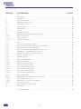
CONTENTS
SECTION DESCRIPTION PAGES
General notices .................................................................................................................................... 3
1. Installation ........................................................................................................................................... 4
1.1 Water connection .................................................................................................................................. 4
1.2 Drain connection ................................................................................................................................. 4
1.3 Electrical connection ........................................................................................................................... 4
1.4 Oven capacity....................................................................................................................................... 4
2. Operation ............................................................................................................................................. 6
2.1 General ................................................................................................................................................ 6
2.2 Control panel ....................................................................................................................................... 7
2.2.1 Machine connected to electrical supply ............................................................................................... 8
2.2.1.1 Time adjustment ................................................................................................................................... 8
2.2.1.2 24h or 12h am/pm ................................................................................................................................ 8
2.2.1.3 Service counter..................................................................................................................................... 8
2.2.2 Start up ................................................................................................................................................. 8
2.2.3 Cooking mode selection ....................................................................................................................... 8
2.2.4 Adjustment of temperature, time or humidity ....................................................................................... 10
2.2.5 Fan speed adjustment ........................................................................................................................... 10
2.2.6 Vent position (convection mode only) .................................................................................................. 10
2.2.7 Humidifyer (convection mode only) ..................................................................................................... 10
2.2.8 Fast cool down ..................................................................................................................................... 10
2.2.9 Core probe function ............................................................................................................................. 11
2.2.10 Delta t function .................................................................................................................................... 11
2.2.11 Cooking phases ph 1/10 ....................................................................................................................... 11
2.2.12 Programme function ............................................................................................................................. 12
2.2.12.1 To write a cooking programme ............................................................................................................ 12
2.2.12.2 To execute a programme ...................................................................................................................... 12
2.2.12.3 To visualise a cooking programme ....................................................................................................... 12
2.2.12.4 To erase a programme .......................................................................................................................... 12
2.2.12.5 To modify a programme ....................................................................................................................... 13
2.2.12.6 To name a programme .......................................................................................................................... 13
2.2.13 Particular functions.............................................................................................................................. 14
2.2.13.1 Vp (pasteurisation value) mode (option) ............................................................................................. 14
2.2.13.2 Oven preheating ................................................................................................................................... 14
2.2.13.3 To program preheat start...................................................................................................................... 14
2.2.14 To switch off the oven ........................................................................................................................... 15
2.3 Daily cleaning and maintenance ......................................................................................................... 16
2.4 Autodiagnostic ..................................................................................................................................... 16
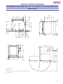
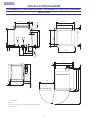
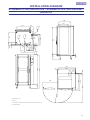
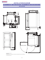
Installation diagram ............................................................................................................................. 50
ENGLISH ...................................................................................................................... page 2 - 17
FRANÇAIS ..................................................................................................................... page 18 - 33
ITALIANO ...................................................................................................................... pagina 34 - 49

- 3 -
GB
GENERAL NOTICES
Machine noise level is less than 70 dB (A)
Important Instructions for Use
- Use in Accordance with Regulations
Hobart Convection Steam Ovens are only intended for baking, roasting, gratinating, steaming and stewing food
products intended for consumption.
- Safety
Do not wash down with a hose or a high pressure cleaner from outside. The “danger” symbol is shown beside
instructions that are essential for the safe operation of the machine. Please read these passages with particular
care.
- Liability
Incorrect installation and repairs not carried out by Hobart Service or their Authorised Service Agent and any
technical modication to the machine not authorised by the manufacturer may cancel the manufacturer
guarantee.
All examples given in these instructions with reference to cooking methods, times and temperatures are dependant
on the quality of the foodstuffs being cooked and may therefore vary.
In the event of the user or the installation technician failing to observe the instructions given in this manual, the
Firm disclaims all responsibility thereof and cannot be held liable for any accident or trouble caused by such non-
observance.
THE MANUFACTURER DISCLAIMS ALL RESPONSIBILITY FOR ANY INACCURACIES IN THIS BOOKLET THAT MAY BE DUE
TO TYPING OR PRINTING MISTAKES. THE MANUFACTURER, MOREOVER, RESERVES RIGHTS TO MAKE MODIFICATIONS
TO THE PRODUCT CONSIDERED USEFUL OR NECESSARY, WITHOUT AFFECTING ITS BASIC FEATURES.

- 4 -
GB
1. INSTALLATION
Before removing packaging, verify good state of the box, in case of damage, give necessary claims to the transport com-
pany.
DOOR OPENING SIDE As standard, the oven is delivered with door hinged on the left. If you want door hinged on the
right, please specify it when you order the oven.
The oven must be installed and connected in accordance with local codes and regulations.
The oven must be installed on a proper-levelled support/floor. Insure levelling of the oven using a spirit level and the top of
the machine as reference.
1.1 WATER CONNECTION
Must be cold, potable and softened water (hardness must be below 7 deg. Clark). Inlet water pressure must be within 2 (mini-
mum) and 6 (maximum) bar, or equivalently within 200 and 600 kPascal. Inlet water tubing should allow a minimum flow
of 13 l/mn.
Maximum theoretical water consumption is:
- 6 level GN 1/1: 25 litres / h for steam production and 60 litres per longest cleaning cycle.
- 10 level GN 1/1: 40 litres / h for steam production and 60 litres per longest cleaning cycle.
- 10 level GN 2/1: 55 litres / h for steam production and 80 litres per longest cleaning cycle.
- 20 level GN 1/1: 70 litres / h for steam production and 80 litres per longest cleaning cycle.
- 20 level GN 2/1: 90 litres / h for steam production and 100 litres per longest cleaning cycle
Provide a suitable pressure hose ½”, B.S.P. union nut 3/4”
1.2 DRAIN CONNECTION
Must be open type and drain material must be suitable for water at a temperature up to 100° C.
Drain connection is B.S.P. 1” external thread.
1.3 ELECTRICAL CONNECTION
Should only be made by Hobart service or other authorised service agents and must be in accordance with the installation
requirements and all relevant regulations.
Connected loads are as follow:
- 6 level GN 1/1: 9 kW 3 phases + neutral + Earth
- 10 level GN 1/1: 18 kW 3 phases + neutral + Earth
- 10 level GN 2/1: 24 kW 3 phases + neutral + Earth
- 20 level GN 1/1: 36 kW 3 phases + neutral + Earth
- 20 level GN 2/1: 48 kW 400V/3 PH/N/E or 42kW 230V/3 PH/E
The oven is supplied without a power cable. The specifications of the power supply connection flexible cable must match or
be superior to those of the cable with rubber insulation H07RN-F.
The oven must be included in an equipotential system whose efficiency must be checked according to the standards in force.
The screw marked by ”Equipotential” label is near the terminal block on the base.
If installation is 400V without neutral the oven will have to be modified by a Hobart service.
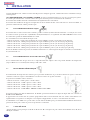
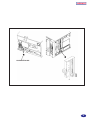
Remove the right side panel to access entry bush joint and terminal blocks.
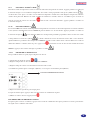
1.4 OVEN CAPACITY
Depending on the model, the oven may accommodate a maximum of 6, 10, 20 or 40 levels. Accordingly it may contain a
maximum of 24, 40, 80 or 160 kg of food.

- 5 -
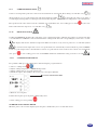
GB
ENTRY BUSH

- 6 -
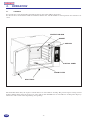
GB
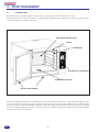
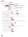
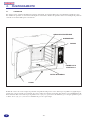
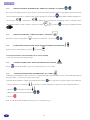
The drain filter must always be in place. Lateral shelves are removable for cleaning. The protection grid covering fan and
heating elements must always be in place for safety and air flow distribution. It is removable for cleaning. The drip trays
will receive and evacuate water drops during door openings.
2.1 GENERAL
To open the door, rotate the handle to horizontal position: door switch will be deactivated.
To close the door, ensure that the handle is horizontal, shut the door, lock the handle in vertical position: door switch is acti-
vated.
2. OPERATION
PROTECTION GRID
GASKET
SHELVES
CONTROL PANEL
DRAIN FILTER
DRIP TRAYS

- 7 -
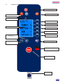
GB
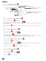
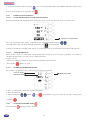
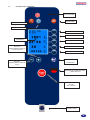
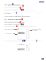
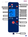
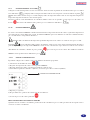
CONVECTION : ON/OFF
ON/OFF SWITCH
HUMIDIFYER + ENTER
START / STOP
COOKING CYCLES
STEAM : ON/OFF
DISPLAY
PROGRAM
SELECTION LINE 1
SELECTION LINE 2
SELECTION LINE 3
SELECTION LINE 4
SELECTION LINE 5
INFRARED COMMUNICATION
WINDOW
PLUS KEY +
SCROLL DOWN
MINUS KEY +
SCROLL UP
CORE PROBE
CONNECTOR
2.2 CONTROL PANEL

- 8 -
GB
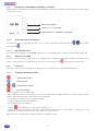
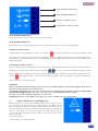
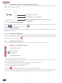
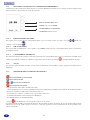
2.2.1 MACHINE CONNECTED TO ELECTRICAL SUPPLY:
When machine is electrically powered, the screen will illuminate and indicate actual time and time left before next descaling
or next service review:
TIME ADJUSTMENT
CHOICE 24h or 12h AM/PM
RESET SERVICE or DELIMING COUNTER
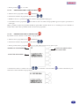
2.2.1.1 TIME AND DATE ADJUSTMENT
To adjust time, press corresponding key (line 3) for 5 seconds, adjust time and date using keys then validate
with enter key .
2.2.1.2 24H OR 12H AM/PM
To switch from 24 h display to 12 h AM/PM display press corresponding key (line 4) until correct time mode is displayed.
2.2.1.3 SERVICE COUNTER
To reset service or descaling counter, press corresponding key (line 5) during 5 seconds. After 15 minutes without any action
on the control panel, the screen will switch off. It can be reactivated by pressing or by opening/closing the door.
2.2.2 START UP
Selecting a cooking mode starts up the oven. To deactivate a cooking mode press again the illuminated key.
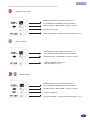
2.2.3 COOKING MODE SELECTION
CONVECTION MODE
STEAM MODE
+ COMBINATION MODE
PROGRAM MODE
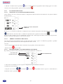
After selecting one of the 3 cooking modes:
- The default temperature corresponding to the selected cooking mode is displayed during 5 seconds (inverted contrast
symbol) and is then replaced by real measured cavity temperature.
- Cavity lights are on (only if door is closed and locked).
- Selected cooking mode keys are illuminated.
- By default timer is in manual mode.
- The key starts (illuminated) or stops (off) cooking process.
- Selecting program mode will deactivate other selected cooking modes. If door is opened during a cooking process, the
cooking process will stop and restart where it was when door is closed again.
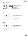
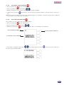
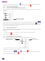
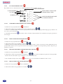
When selecting a cooking mode, the display will show the following screen:

- 9 -
GB
CONVECTION MODE
TIMER MANUAL MODE
VENT POSITION
FAN SPEED AND VP (option)
DEFAULT TEMPERATURE DURING 5 Secs.
THEN REAL CAVITY TEMPERATURE
STEAM MODE
DEFAULT TEMPERATURE DURING 5 Secs.
THEN REAL CAVITY TEMPERATURE
TIMER MANUAL MODE
FAN SPEED AND VP (option)
+ COMBINATION MODE
TIMER MANUAL MODE
HUMIDITY LEVEL
FAN SPEED AND VP (option)
DEFAULT TEMPERATURE DURING 5 Secs.
THEN REAL CAVITY TEMPERATURE

- 10 -
GB
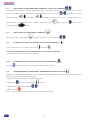
2.2.4 ADJUSTMENT OF TEMPERATURE, TIME OR HUMIDITY .
To adjust one of the above settings, select the line by pressing the corresponding key located on the right side of the screen
(inverted contrast symbol) then adjust desired value with the two keys . In combination mode the display will show
addition or evacuation of humidity. If a cooking time has been set and it is desired to come back to
manual mode (continuous cooking), select the line then press until the manual symbol appears.
2.2.5 FAN SPEED ADJUSTMENT
Select the corresponding line and adjust speed 1 to 4 using keys .
2.2.6 VENT POSITION (CONVECTION MODE ONLY)
Press the corresponding key to open or close .
IT IS NOT NECESSARY TO VALIDATE WITH THE ENTER KEY:
Values are automatically taken into account.
2.2.7 HUMIDIFYER (CONVECTION MODE ONLY)
The key allows injecting water in the cavity during cooking process.
2.2.8 FAST COOL DOWN
Whatever cooking mode has been selected, it is possible to automatically cool down the cavity by water injection in the fan:
1) Press line 3 key (timer)
2) Press until the symbol appears.
3) Adjust desired final temperature .
4) Start
Note: Choosing another mode will stop above process

- 11 -
GB
2.2.9 CORE PROBE FUNCTION
Connect core temperature probe into connector located at bottom of control panel. Press during 5 seconds line 3 key
display indicates set core probe temperature and shows following symbol on the right side of the screen. After 5
seconds displayed temperature is real temperature measured by the probe. Adjust desired set temperature as described before.
Place probe into the centre of the food to be controlled, close and lock the door, start cooking process with key. To come
back to timer function, depress for 5 seconds line 3 key .
2.2.10 DELTA T FUNCTION
Cooking with DELTA T automatically controls the cavity cooking temperature, following the product core temperature with
a constant difference. DELTA T can be used with all three cooking modes. Press the corresponding key to line 2 for 5 seconds
the display indicates the default set temperature difference between cavity and core probe for 5 seconds. The symbol
is contrasted on the right of the screen. Core probe function is automatically activated. Adjust set points for DELTA
T and core probe temperatures as described above. Insert core probe into the centre of the food to control, close and lock the
door, press to start cooking process. To cancel DELTA T function, maintain line 2 key pressed for 5 seconds .
2.2.11 COOKING PHASES PH 1/10
It is possible to link up to 10 cooking phases without using the program function.
1) Select a cooking mode .
2) Adjust cooking temperature or DELTA T temperature.
3) Adjust cooking time or core probe temperature.
4) Validate first phase line1 (PH 1/1) the screen goes to next phase (PH 2/2).
5) Reiterate for each phase.
6) After the last phase press the phase validation key twice.
7) Start cooking process by pushing
TO ERASE ONE COOKING PHASE
When the phase to be erased is displayed press the phase validation key for 5 seconds then release.
PHASE VALIDATION KEY

- 12 -
GB
2.2.12 PROGRAMME FUNCTION
It is possible to write and store up to 100 cooking programmes of 10 phases each.
2.2.12.1 TO WRITE A COOKING PROGRAMME
1- Press programme key. The key will illuminate.
2- Select programme number under which you want to save: .
3- Write and validate all the phases of the new cooking programme. The programme number will blink to indicate that it has
not been stored yet.
4- Validate programme : Buzzer is activated and programme number will be inverted contrast in order to indicate
saving.
2.2.12.2 TO EXECUTE A PROGRAMME
1- Press programme key The key will illuminate.
2- Select programme number that you want: .
3- Start cooking programme The buzzer will be activated at each phase change.
4- The display will show total remaining time until the end of cooking, unless some phases are using core probe temperature.
Pressing one of the line keys will display the corresponding set parameter for the operating phase.
2.2.12.3 TO VISUALISE A COOKING PROGRAMME
1- Press programme key The key will illuminate.
2- Select programme number to be visualised: . The screen will display the first phase of the programme. Press the
phase key (line 1) to visualise and scroll through other phases.
3- To check total time, activate (Except if one of the phases is using core probe).
2.2.12.4 TO ERASE A PROGRAMME
1- Press programme key The key will illuminate.
2- Select programme number to be erased: .
3- Maintain key pressed for 5 seconds.
PROGRAMME NAME
PHASE KEY AND FIRST LINE
SELECTION KEY
KEYS FOR LINE SELECTION OR
SPECIAL FUNCTIONS
PROGRAMME N°
PHASE N°
NUMBER
OF PHASES

- 13 -
GB
2.2.12.5 TO MODIFY A PROGRAMME
1- Press programme key The key will illuminate.
2- Select programme number to be modified: .
3- Modify desired phases and parameters: The programme number will blink.
4- Validate new programme : The buzzer is activated and the programme number is inverted contrast to indicate sa-
ving.
Notes: You can run a modified programme before validation. In that case, validation can be done after the end of cooking. It
is not possible to insert a phase into a programme.
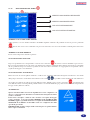
2.2.12.6 TO NAME A PROGRAMME
It is possible to associate a name with a programme number:
1- Press programme key the key will illuminate.
2- Select programme number to be named: .
3- Maintain programme key pressed during 4 seconds. The screen will display the following:
4- Select letters or numbers with the keys and validate with the enter key Selected characters will locate at
the right of the programme number:
ERASE CHARACTER KEY
AVAILABLE CHARACTERS
PROGRAMME NUMBER

- 14 -
GB
5- At the end validate the name by pressing for 5 seconds. Programme number stops blinking and buzzer sounds. If you
wish to exit programme press programme key .
2.2.13 PARTICULAR FUNCTIONS
2.2.13.1 VP (PASTEURISATION VALUE) MODE (OPTION)
This function must be selected during initial configuration of the oven. It can only work when core probe is used.
Press 5 seconds the line 5 key, display of VP will contrast. Adjust desired VP using keys .
One push on line 5 key will change from VP adjustment to fan speed adjustment.
Cooking cycle will only end when set VP and set core probe temperature are reached. To deactivate VP, set VP value at 0.
2.2.13.2 OVEN PREHEATING
When you have selected a cooking mode, adjusted temperature and time or if you are using a programme, it is possible to
automatically preheat the oven at the correct cooking temperature.
In order to do so:
- Write your cooking programme or call an existing programme from the memory
- Press the key during 5 seconds.
2.2.13.3 TO PROGRAM PREHEAT START
It is possible to program the oven in order to start preheating at a given time.
1- Select a cooking mode, adjust desired preheat temperature.
2- Press the selection key.
3- Adjust starting time validate start . It is possible to stop process either by selecting a cooking mode
or pushing .
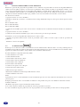
2.2.14 TO SWITCH OFF THE OVEN
Press the off key the display will be as follow:
VP KEY FAN SPEED KEY
SELECTION KEY
STARTING TIME
ACTUAL TIME

- 15 -
GB
STOP WITH BOILER DRAIN
At end of the day if you do not want to carry out a cleaning cycle.
STOP WITH BOILER FULL
For a temporary stop during the day and you plan to use the oven soon there is no need to empty the boiler.
MANUAL CLEAN CYCLE
After pushing the corresponding key, start the cycle with the key. The oven will start in steam mode. A buzzer sound
will advise you to spray the entire cavity with an appropriate detergent, taking all safety measures recommended by the de-
tergent supplier. After closing the door, the cycle will restart and end up with appropriate rinsing of the cavity, followed by a
double boiler drain.
AUTOMATIC CLEAN CYCLE
Before starting an automatic cleaning cycle, verify that you have enough detergent left in the detergent container and that the
pump tube is correctly inserted in the container. Using the keys you can change the amount of detergent (from 0
TO 8) which will be used during the cleaning cycle depending on the degree of dirtiness of your machine. Then start the cycle
with the key. Depending on the status of your machine the cleaning cycle may start with a cool down to bring the ma-
chine at the correct washing temperature.
WARNING:
That screen indicates that the cleaning cycle has not been successfully completed or has been interrupted. There may be
some detergent left in the cavity or in the boiler.
You must thoroughly rinse the cavity of the oven and carry out a double drainage of the boiler (using the STOP WITH
BOILER DRAIN PROGRAM). Or you can select and carry out the MANUAL CLEAN CYCLE.
Do not use the machine without completing one of the above.
IMPORTANT: Always wait complete end of the process before switching of water and electricity.
2.3 DAILY CLEANING AND MAINTENANCE
Remove main pieces of food, which could have fallen in the cavity before star-
ting a cleaning cycle. Perform at least one daily cleaning cycle. Make sure that
the door gasket is clean in order to keep its longevity, wipe it out with a soft wet
cloth after cleaning cycle. Do not use abrasive pads on the glass or stainless steel
surfaces or door gasket, in case of hard to remove stains use an appropriate non
corrosive detergent. Depending on water hardness, you may have to descale the
boiler or the cavity.
To descale the boiler:
- Switch off the oven with boiler drain.
STOP WITH BOILER DRAIN
STOP WITH BOILER FULL
MANUAL CLEAN CYCLE
AUTOMATIC CLEAN CYCLE

- 16 -
GB
- Fill up the boiler with white vinegar or similar descaling product using the steam inlet at the top right hand side of the ca-
vity.
6 level ovens: 5 litres
10 level ovens: 6 litres
20 level ovens: 10 litres
- Select steam mode without starting cycle and wait 30 to 45 minutes depending on the strength of the descaling pro-
duct.
- Switch off the oven with boiler drain.
- Select steam mode again without starting cycle to rinse the boiler.
- End up with a cleaning cycle.
To descale the cavity:
-Spray on all parts of the cavity a descaling product and let react according to the manufacturer specifications.
-End up with a cleaning cycle.
2.4 AUTODIAGNOSTICS
The microprocessor of your oven constantly checks the proper functioning of the machine, and advises you by a symbol
located on the bottom right of the screen of possible faults on the oven. That symbol appears in place of the fan speed
symbol. Faults are numbered and the corresponding number will be displayed in the screen:
0 Electronic components overheat (CPU)
1 Cavity overheat
2 Boiler overheat
3 Cavity probe fault
4 Vent probe fault
5 Condensates probe fault
6 Boiler probe fault
7 Core probe fault or not connected
8 Fan motor fault
9 Lack of water in the boiler
10 Building energy optimisation system in action
11 Static relays overheat
Notes:
Faults must be corrected otherwise they will be displayed each time a function using the faulty component is selected.
The fault display stays on if the corresponding mode or function cannot be used. Select another mode or function.
The five last faults are memorised and dated.
If a fault occurs during a cooking programme, that programme will stop.
16 If a fault is displayed before starting a programme, it will not be possible to activate that programme.

- 17 -
GB
TEMPORARY OPERATION OF THE OVEN IN CASE OF FAULTS
These functions are only here to help you finish your work in case of faulty component. Call your service technician
for repair. Do not use constantly the oven under these functions.
CONVECTION MODE: If the cavity probe is faulty stop the oven and then press the convection key for 10 seconds
. Temperature will be regulated at around 160°C by the core probe, which must be inserted into the cavity and attached
to one of the shelf.
STEAM MODE: If the boiler is faulty, stop the oven . Press steam key for 10 seconds . Steam will be produced by
water injection in the fan at around 100°C. In both of these modes, it is not possible to adjust temperature or select a cooking
time you can only start or stop the cooking cycle by pressing to exit these modes and return to standard modes press
.

- 18 -
F
SOmmAIRE
CHAPITRE DESCRIPTION PAGE
Remarques ...................................................................................................................................... 19
1. Installation .......................................................................................................................................... 20
1.1 Raccordement hydraulique ................................................................................................................. 20
1.2 Raccordement du tuyau de vidange .................................................................................................... 20
1.3 Branchement électrique ...................................................................................................................... 20
1.4 Capacité four ....................................................................................................................................... 20
2. Fonctionnement ................................................................................................................................... 22
2.1 Généralités .......................................................................................................................................... 22
2.2 Panneau de contrôle ............................................................................................................................ 23
2.2.1 Machine branchée a l’alimentation électrique ................................................................................... 24
2.2.1.1 Réglage de l’heure .............................................................................................................................. 24
2.2.1.2 Sélection 24 h ou 12h am/pm .............................................................................................................. 24
2.2.1.3 Compteur d’entretien .......................................................................................................................... 24
2.2.2 Allumage du four ................................................................................................................................. 24
2.2.3 Sélection d’un mode de cuisson .......................................................................................................... 24
2.2.4 Réglage de la température, temps de cuisson ou humidité ................................................................. 26
2.2.5 Réglage de la vitesse de la turbine ...................................................................................................... 26
2.2.6 Position oura (en mode convection seulement) ................................................................................... 26
2.2.7 Humidificateur (en mode convection seulement) ................................................................................ 26
2.2.8 Baisse rapide de la température dans l’enceinte ................................................................................. 26
2.2.9 Fonction sonde à cœur ........................................................................................................................ 27
2.2.10 Fonction Delta T ................................................................................................................................. 27
2.2.11 Phases de cuisson PH 1/10 ................................................................................................................. 27
2.2.12 Fonction programme ........................................................................................................................... 28
2.2.12.1 Enregistrement d’un programme ......................................................................................................... 28
2.2.12.2 Exécution d’un programme ................................................................................................................. 28
2.2.12.3 Affichage d’un programme .................................................................................................................. 28
2.2.12.4 Effacement d’un programme ............................................................................................................... 28
2.2.12.5 Modification d’un programme ............................................................................................................ 29
2.2.12.6 Appellation d’un programme .............................................................................................................. 29
2.2.13 Fonctions particulières ........................................................................................................................ 30
2.2.13.1 Mode VP (valeur de pasteurisation) (option) ..................................................................................... 30
2.2.13.2 Préchauffage du four ........................................................................................................................... 30
2.2.13.3 Programme du préchauffage ............................................................................................................... 30
2.2.14 Arrêt du four ........................................................................................................................................ 31
2.3 Nettoyage quotidien et entretien ......................................................................................................... 32
2.4 Autodiagnostic .................................................................................................................................... 32
Schémas d’installation ........................................................................................................................ 50

- 19 -
F
REmARQUES
L’émission sonore de la machine est inférieure à 70 dB (A).
Consignes d’utilisation
- Utiliser le four conformément aux instructions contenues dans ce manuel.
Les fours mixtes à convection et vapeur ne sont adaptés que pour la cuisson, le rôtissage, le gratinage, la cuisson
à la vapeur et à l’étouffée d’aliments destinés à la consommation.
- Sécurité
Il est interdit de nettoyer le four avec un jet d’eau ou un nettoyeur haute pression. Le pictogramme «danger »
veut attirer l’attention du lecteur sur des consignes importantes pour un fonctionnement en toute sûreté du
four. Ces consignes doivent être lues avec beaucoup d’attention.
- Responsabilité
Une erreur d’installation, une réparation non effectuée par le personnel Hobart ou un centre SAV agréé, ainsi
que toute modication non autorisée par le fabricant rend la garantie caduque.
Toutes les méthodes, durées et temps de cuisson reportés dans ce manuel sont donnés à titre d’exemple et
dépendent de la qualité des aliments à cuire.
Le fabricant décline toute responsabilité en cas de dégâts corporels ou matériels provoqués par le non-respect des
instructions reportées dans ce manuel.
LE FABRICANT DECLINE AUSSI TOUTE RESPONSABILITE EN CAS DE DEGATS CORPORELS OU MATERIELS
PROVOQUES PAR UNE ERREUR D’INTERPRETATION OU DES ERREURS D’IMPRESSION DE CE MANUEL. LE
FABRICANT SE RESERVE LE DROIT D’APPORTER TOUTES LES MODIFICATIONS QU’IL JUGERA UTILES, SANS
INFLUER SUR LES CARACTÉRISTIQUES DE BASE DU PRODUIT.

- 20 -
F
1. INSTALLATION
Avant de déballer le four, vérifier l’état du colis. En présence de dégâts apparents, veuillez adresser les réclamations d’usage
au transporteur.
OUVERTURE DROITE / GAUCHE DE LA PORTE : Le four est généralement livré avec la porte s’ouvrant par la gauche.
Les clients qui souhaitent une ouverture à droite de la porte doivent le préciser au moment de la commande.
Le four doit être installé et branché conformément à la législation locale en la matière.
Le four doit être installé sur un support ou un plancher de niveau. Vérifier la mise à niveau du four avec un niveau à bulle, en
prenant le sommet du four comme point de repère.
1.1 RACCORDEMENT HYDRAULIQUE
Le four doit être raccordé à un réseau d’eau froide, potable et adoucie (la dureté doit être inférieure à 7° français). Le réseau
d’eau doit avoir une pression entre 2 (minimum) and 6 (maximum) bars, ou également entre 200 et 600 kPascal. Le réseau
d’eau doit ainsi garantir un débit minimum de 13 l/mn.
La consommation d’eau maximale théorique est de :
- GN 1/1 à 6 niveaux : 25 l/h pour la production de vapeur et 60 litres pour le cycle de nettoyage le plus long.
- GN 1/1 à 10 niveaux : 40 l/h pour la production de vapeur et 60 litres pour le cycle de nettoyage le plus long.
- GN 1/1 à 10 niveaux : 55 l/h pour la production de vapeur et 80 litres pour le cycle de nettoyage le plus long.
- GN 1/1 à 20 niveaux : 70 l/h pour la production de vapeur et 80 litres pour le cycle de nettoyage le plus long.
- GN 1/1 à 20 niveaux : 90 l/h pour la production de vapeur et 100 litres pour le cycle de nettoyage le plus long.
Prévoir un flexible rèsistant à la pression, de diamètre intérieur d’1/2”, d’une longueur adéquate et muni de raccords femelles
de jonction B.S.P. 3/4”.
1.2 RACCORDEMENT DU TUYAU DE VIDANGE
Le raccordement doit être de type ouvert et sa composition doit être adaptée à de l’eau pouvant atteindre une température
jusqu’à 100°C. Le raccord du tuyau de vidange est B.S.P. 1” màle.
1.3 BRANCHEMENT ÉLECTRIQUE
Le branchement électrique doit être effectué par le personnel du fabricant ou par d’autres électriciens agréés, et doit être
conforme à toutes les exigences d’installation et à toutes les normes en vigueur en matière.
Les puissances installèes sont les suivantes :
- GN 1/1 à 6 niveaux : 9 kW 3 phases + neutre + Terre
- GN 1/1 à 10 niveaux : 18 kW 3 phases + neutre + Terre
- GN 2/1 à 10 niveaux : 24 kW 3 phases + neutre + Terre
- GN 1/1 à 20 niveaux : 36 kW 3 phases + neutre + Terre
- GN 2/1 à 20 niveaux : 48 kW 400V/3 PH/N/T ou 42kW 230V/3 PH/T
L’appareil est livré sans câble d’alimentation. Le flexible pour le branchement à la ligne électrique doit être conforme au
flexible modèle H07RN-F.
L’appareil doit être inclus dans un système équipotentiel dont le fonctionnement doit être vérifié conformément à la
réglementation en vigueur. La vis marquée avec l’étiquette “Equipotentiel” se trouve à côté du bornier sur la base.
Si l’installation est en 400V et n’a pas de neutre, le four doit être modifié par le personnel du fabricant Hobart. Démonter le
panneau de droite pour accéder au presse étoupe d’entrée et au bornier.
1.4 CAPACITÉ FOUR
Selon le model, le four peut loger 6, 10, 20 ou 40 niveaux. En conséquence il peut contenir un maximum de 24, 40, 80 ou
160 kg de nourriture.
La pagina si sta caricando...
La pagina si sta caricando...
La pagina si sta caricando...
La pagina si sta caricando...
La pagina si sta caricando...
La pagina si sta caricando...
La pagina si sta caricando...
La pagina si sta caricando...
La pagina si sta caricando...
La pagina si sta caricando...
La pagina si sta caricando...
La pagina si sta caricando...
La pagina si sta caricando...
La pagina si sta caricando...
La pagina si sta caricando...
La pagina si sta caricando...
La pagina si sta caricando...
La pagina si sta caricando...
La pagina si sta caricando...
La pagina si sta caricando...
La pagina si sta caricando...
La pagina si sta caricando...
La pagina si sta caricando...
La pagina si sta caricando...
La pagina si sta caricando...
La pagina si sta caricando...
La pagina si sta caricando...
La pagina si sta caricando...
La pagina si sta caricando...
La pagina si sta caricando...
La pagina si sta caricando...
La pagina si sta caricando...
La pagina si sta caricando...
La pagina si sta caricando...
-
 1
1
-
 2
2
-
 3
3
-
 4
4
-
 5
5
-
 6
6
-
 7
7
-
 8
8
-
 9
9
-
 10
10
-
 11
11
-
 12
12
-
 13
13
-
 14
14
-
 15
15
-
 16
16
-
 17
17
-
 18
18
-
 19
19
-
 20
20
-
 21
21
-
 22
22
-
 23
23
-
 24
24
-
 25
25
-
 26
26
-
 27
27
-
 28
28
-
 29
29
-
 30
30
-
 31
31
-
 32
32
-
 33
33
-
 34
34
-
 35
35
-
 36
36
-
 37
37
-
 38
38
-
 39
39
-
 40
40
-
 41
41
-
 42
42
-
 43
43
-
 44
44
-
 45
45
-
 46
46
-
 47
47
-
 48
48
-
 49
49
-
 50
50
-
 51
51
-
 52
52
-
 53
53
-
 54
54


Hobart HFEI D Series Installation, Use And Maintenance Instructions
- Categoria
- Forni
- Tipo
- Installation, Use And Maintenance Instructions
in altre lingue
- English: Hobart HFEI D Series
- français: Hobart HFEI D Series
Documenti correlati
Altri documenti
-
Rational 6 GN 1/1 Istruzioni per l'uso
-
-
Electrolux AOS61-EL Manuale utente
-
Unox BakerTop Manuale utente
-
MBM MC201E Use And Routine Maintenance Manual
-
-
Hoover HOFZ7170IN Manuale utente
-
Angelo Po FX101 E 1-2CR Use And Installation Manual
-
Univex Double Rack Rotating Manuale del proprietario
-
 Hobart Ecomax Plus F515SW-10C Manuale del proprietario
