
Connected
OCPP 1.6


English - 1 -
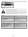
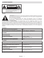
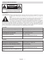
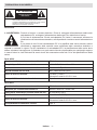
SAFETY PRECAUTION
CAUTION
RISK OF ELECTRIC SHOCK:
CAUTION: VESTEL ELECTRIC VEHICLE CHARGER STATION SHALL
BE MOUNTED BY A LICENSED OR AN EXPERIENCED
ELECTRICIAN IN ALIGN WITH ANY REGIONAL OR
NATIONAL ELECTRIC REGULATIONS AND STANDARDS IN
EFFECT.
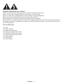
Warnings
1- WARNING: Danger of injury or electric shock. Prior to connecting EV charger electric supply, disconnect
the power on AC mains side or the load centre.
2) On the AC mains side of Vestel EV charger, the Circuit Breaker, Leaking Current Relay
and AC mains cable combination must be used.
3) EV charger AC grid connection and load planning shall be reviewed and approved by
authorities as specied by the regional or national electric regulations and standards in
eect. For multiple EV charger installations the load plan shall be evaluated accordingly.
The manufacturer shall not be held liable for any reason whatsoever in the event of damages and risks that
are borne of errors due to AC grid supply connection and load planning.
AC22 Series
Built-in Residual Current Sensing module DC 6mA
Electric Infrastructure Requirements 400VAC 50/60 Hz - 3-phase 32A
Required Circuit Breaker on AC Grid 4P-40A MCB Type-C
Required RCCB on AC Grid 40A - 30mA RCCB Type-A
Required AC Grid Cord 5 x 6mm² (< 50m)
External Dimensions: Ø 15-21 mm
Vehicle charger Compatibility Type -2
AC11 Series
Built-in Residual Current Sensing module DC 6mA
Electric Infrastructure Requirements 400VAC 50/60 Hz - 3-phase 16A
Required Circuit Breaker on AC Grid 4P-20A MCB Type-C
Required RCCB on AC Grid 20A - 30mA RCCB Type-A
Required AC Grid Cord
5 x 4mm2 (< 50m)
External Dimensions: Ø 15-21 mm
Vehicle charger Compatibility Type -2

English - 2 -
WARNING REGARDING WALL MOUNT
1) Prior to mounting your charging station on the wall, read these instructions.
2) Do not mount your charging station to the ceiling or an inclined wall.
3) Do not mount your charging station in close proximity to heating appliances.
4) Use the wall mounting screws and other accessories specied.
5) This appliance is classied as indoor and outdoor mount compatible.
6) If the device is mounted outside the building, the hardware that will be used to connect the conductors to
the appliance shall be compatible with outdoor use and the appliance shall be mounted preserving the IP
rate of the appliance.
Tools for Mounting:
•(1x) Drill
•(1x) Drill bit Ø8mm
•(1x) Hammer (for dowels)
•(1x) Torkx T25 (Safe) Screw driver
•(1x) PH2/PH3 Phillips Screw driver
•(1x) Flat (Clamp type) Screw driver
•(1x) Water gauge
•(1x) Side Cutter
•(1x) Volt Indicator

English - 3 -
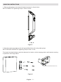
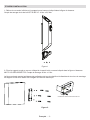
MOUNTING INSTRUCTIONS
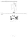
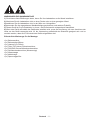
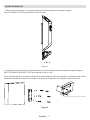
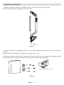
1- Remove the bottom cover and wall bracket as shown in gure below.
M5*15 SCREW-T25 Tightening Torque: 4 Nm ± 0,5 Nm
Figure 1
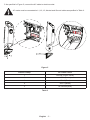
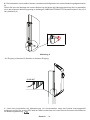
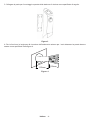
2- Mount the wall mount part on the wall as specied below with using water gauge.
M6*75 SECURE SCREW-T25 Tightening Torque: 8 Nm ± 1 Nm
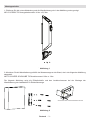
The dowel hole depth distance and hole diameter for electric vehicle charging station wall bracket mounting
is specied in the image below.
8
5
5
5
Ø
7
3
3
165
DRAWING OF SCREW ANCHOR HOLES
Figure 2

English - 4 -
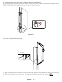
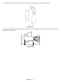
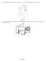
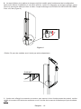
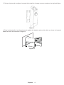
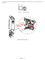
3- Attach the charging station wall mounting part as specied below.
Figure 3
4- For supply, the external insulation removal lengths for the cables through the wall shall be as specied in
gure 4.
150mm
150mm
Figure. 4

English - 5 -
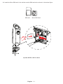
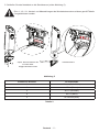
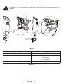
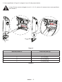
5- As specied in Figure 5, connect the AC cable to electric socket.
AC mains must be connected to L1, L2, L3, Neutral and Ground cables as specied in Table 2.
Figure 5
Electric Clamp AC Cable Colour
1 Ground (Green-Yellow)
2 AC L1 (Brown)
3 AC L2 (Black)
4 AC L3 (White)
5 AC Neutral (Blue)
Table 2

English - 6 -
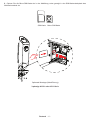
6 - Insert the Micro SIM card in the cellular module SIM card slot as shown in the below gure.
SIM card Micro SIM Card
3 phase AC22 or AC11 series

English - 7 -
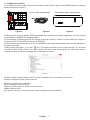
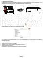
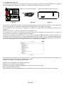
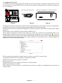
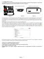
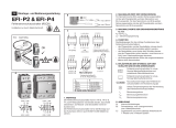
7 - Conguration with PC
7.1 Connect the control cable in Figure b, the consol socket (CN 6) in gure a and DEBUG socket in charging
station test device in gure c.
Control cable (accessor�es) Test adapter stat�on (accessor�es)
Console UART
USB
Figure.a Figure.b Figure.c
7.2 Energize the charging station. LED illuminated button will blink red during conguration, you can proceed
to next steps to congure the charging station.
7.3 Connect the Console port of the EV charger (Figure a) to the EVC Tester Console UART port (Figure c).
7.4 Connect EVC Tester USB port to the PC USB port.
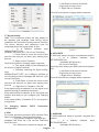
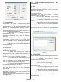
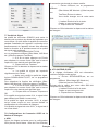
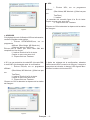
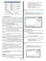
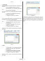
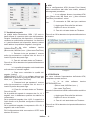
7.5 When serial port connection with PC is established, the serial communication port will be displayed in
the device manager
(COM number may dier). If you see
icon, PC serial connection port is missing drivers, you will have
to install PL2303_Prolic_Driver. You can download this driver from www.prolic.com. When the driver is
installed correctly, the device manager will be displayed as below.
Picture.1
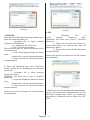
7.6 When Vestel charging station and PC serial connection port is connected, you can use
Teraterm software to input console records.
a) Click on Install on the Upper Bar
b) Go to Serial Connection Point
c) Select COM number for Serial Connection Point
d) Baud Speed is 600
e) In picture 2 below, all serial connection point congurations are specied.

English - 8 -
Picture.2
7.7 Signal Quality
GSM / 3G connection quality will vary based on
the operator grid coverage area. During device
installation, the connection quality must be checked.
The device direction and placement must be
completed where the signal quality is best.
i. In a dierent software input
SIGNALQUALITY;ON;
(Notepad, MS Word etc.) (Do not use TeraTerm)
ii. Press Enter to move the cursor to the
next line and copy all you have input starting from
this line.
iii. Right click on Teraterm.
Click OK and wait for charging station response.
iv. The signal quality will be displayed on
the screen in regular intervals.
v. Following checking the signal quality,
input
SIGNALQUALITY;OFF; at a dierent software to
turn o control function (Notepad, MS Word etc.) (Do
not use TeraTerm).
vi. Press Enter to move the cursor to the
next line and copy all you have input starting from
this line.
vii. Right click on Teraterm. Click OK.
If the signal quality is between 0-14, the signal is not
powerful enough to establish connection.
If the signal quality is between 14-22, the signal is at
medium level and you can congure your charging
station.
If the signal quality is between 22-31, the signal is
at high level.
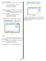
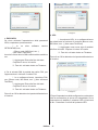
7.8 Charging Station OCPP Connection
Conguration
a. APN
For mobile grid data connection APN (Access Point
Name) conguration, follow the steps below.
i. In a dierent software, input APN;xxx;
(Notepad, MS Word etc.) (Do not use TeraTerm)
Input the value
Your SIM card is required to change xxx.
ii. Add Enter to the end of the text.
Copy what you have input.
iii. Right click on Teraterm.
Click OK and wait for charging station response.
Picture.3
b. APN USER
IF APN user setup is required, complete this section.
iv. In a dierent software, input
SETAPNUSER;xxx;
. (Notepad, MS Word etc.)
(Do not use TeraTerm)
Input the value where your SIM card should replace
xxx.
v. Add Enter to the end of the text.
Copy what you have input.
vi. Right click on Teraterm.
Click OK and wait for charging station response.
Picture.4
c. APNPASS
IF APN password setup is required, complete this
section.
i. In a dierent software, input
SETAPNPASS;xxx;
. (Notepad, MS Word etc.)

English - 9 -
(Do not use TeraTerm)
Input the value where your SIM card should replace
xxx.
ii. Add Enter to the end of the text.
Copy what you have input.
iii. Right click on Teraterm.
d. If SIM card has PIN code protection, PIN code is
required for approval.
i. In a dierent software, input PIN;xxx;
(Notepad, MS Word etc.) (Do
not use TeraTerm)
ii. Add Enter to the end of the text.
Copy what you have input.
iii. Right click on Teraterm.
Click OK and wait for charging station response.
Picture.4
e. URL
i. Input URL; at a dierent software to turn
o control function (Notepad, MS Word etc.) (Do not
use TeraTerm)
ii. Add a new line character at the end of
the text. Copy what you have input.
iii. Right click on Teraterm.
Click OK and wait for charging station response.
Picture.5
f. After conguration setting, wait for the server
connection to be completed. If the connection is
established, LED button will illuminate blue. Check
the LED button colour.

English - 10 -
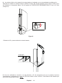
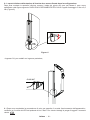
8 - Charging station lower door shall be attached following conguration.
After mounting the lower door, tighten the cable coupling nut to x the cable as specied in the gure below.
CABLE COUPLING NUT Tightening Torque: 5 Nm ± 0.5 Nm (Figure.6)
Figure. 6
• AC input, for models with rear input;
GLAND NUT
9 - After completing mains connection; to ensure the proper operation of the appliance, please check whether
the LED colour of the button is solid blue. For other details please read the user manual.

Deutsch - 1 -
SICHERHEITSHINWEISE
VORSICHT
STROMSCHLAGRISIKO:
ACHTUNG: DIE INSTALLATION DES VESTEL ELEKTROFAHRZEUG-
LADEGERÄTS DARF NUR VON EINEM ZUGELASSENEN
UND ERFAHRENEN ELEKTRIKER IN ÜBEREINSTIMMUNG
MIT ALLEN GELTENDEN REGIONALEN UND
NATIONALEN ELEKTROVORSCHRIFTEN UND -NORMEN
DURCHGEFÜHRT WERDEN.
Hinweis:
1) WARNUNG: Elektroschock- oder Verletzungsgefahr. Schalten Sie die Stromversorgung
an der Wechselstromseite oder am Lastzentrum aus, bevor Sie das EV-Ladegerät an die
Stromversorgung anschließen.
2) Auf der Wechselstromseite des Vestel EV-Ladegeräts müssen die folgenden
Schutzschalter-, Fehlerstromrelais- und Wechselstromkabelkombination je nach Modell
verwendet werden.
3) Das Ladegerät für Elektrofahrzeuge, der Netzanschluss und der Lastplanung müssen von einer
autorisierten Person gemäß den geltenden regionalen und nationalen Vorschriften und Normen geprüft und
genehmigt werden. Bei einer großen Anzahl von Elektrofahrzeug-Ladeeinrichtungen muss die Lastplanung
entsprechend bewertet werden. Was auch immer die Umstände sind, der Hersteller haftet weder direkt noch
indirekt für Schäden oder Risiken, die durch Fehler im Wechselstrom-Anschluss und in der Lastplanung
auftreten.
AC22-Serie
DC Fehlerstromerkennung eingebaut 6mA
Anforderungen an die elektrische Infrastruktur 400VAC 50/60 Hz - 3-phasig 32A
Erforderlicher Schutzschalter im Wechsel-
stromnetz
4P-40A MCB Tip-C
Erforderlicher FI-Schutzschalter auf
Wechselstromnetz
40A - 30mA RCCB Typ-A
Erforderliches Netzkabel 5 x 6mm² (< 50m)
Außenmaße: Ø 15-21 mm
Kompatibilität mit Fahrzeugladekabeln Typ 2
AC11-Serie
DC Fehlerstromerkennung eingebaut 6mA
Anforderungen an die elektrische Infrastruktur 400VAC 50/60 Hz - 3-phasig 16A
Erforderlicher Schutzschalter im Wechsel-
stromnetz
4P-20A MCB Tip-C
Erforderlicher FI-Schutzschalter auf
Wechselstromnetz
20A - 30mA RCCB Typ-A
Erforderliches Netzkabel
5 x 4mm2 (< 50m)
Außenmaße: Ø 15-21 mm
Kompatibilität mit Fahrzeugladekabeln Typ 2

Deutsch - 2 -
WARNUNGEN ZUR WANDMONTAGE
1) Sie müssen diese Erklärungen lesen, bevor Sie Ihre Ladestation an die Wand installieren.
2) Montieren Sie die Ladestation nicht an einer Decke oder an einer geneigten Wand.
3)Installieren Sie die Ladestation nicht in der Nähe von Heizgeräten.
4)Verwenden Sie die angegebenen Wandbefestigungsschrauben und anderes Zubehör.
5)
6) Wenn das Gerät außerhalb des Gebäudes installiert wird, muss die Ausrüstung, die zum Anschluss der
Leiter an das Gerät verwendet wird, für die Verwendung außerhalb des Standorts geeignet sein und so
montiert werden, dass die IP-Schutzart des Geräts eingehalten wird.
Erforderliche Werkzeuge für die Montage:

Deutsch - 3 -
Montageschritte
1- Entfernen Sie die untere Abdeckung und die Wandhalterung wie in der Abbildung unten gezeigt.
M5*15 SCREW-T25 Anzugsdrehmoment: 4 Nm ± 0,5 Nm
Abbildung 1
2- Montieren Sie die Wandhalterung mithilfe der Wasserwaage an der Wand, wie in der folgenden Abbildung
dargestellt.
Die folgende Abbildung zeigt die Dübellochtiefe und den Lochdurchmesser bei der Montage der
Wandhalterung der Ladestation für Elektrofahrzeuge.
8
5
5
5
Ø
7
3
3
165
ZEICHNUNG DER SCHRAUBENANKERLÖCHER
Abbildung 2

Deutsch - 4 -
3- Installieren Sie die Ladestation wie in der Abbildung unten gezeigt an der Wandhalterung.
Abbildung 3
4- Die äußeren Abisolierabmessungen des Kabels, die von der Wand für die Einspeisung kommt, sollte der
Abbildung 4 entsprechen.
150mm
150mm
Abbildung 4

Deutsch - 5 -
5- Schließen Sie das Netzkabel an die Steckdose an (siehe Abbildung 5).
Die L1-, L2-, L3-, Neutral- und Masseleitungen des Wechselstromnetzes müssen gemäß Tabelle
2 angeschlossen werden.
Abbildung 5
Elektrische Klemme AC-Kabelfarbe
1 Masse (Grün-Gelb)
2 AC L1 (Braun)
3 AC L2 (Schwarz)
4 AC L3 (Weiß)
5 AC Neutral (Blau)
Tabelle 2

Deutsch - 6 -
6 - Setzen Sie die Micro-SIM-Karte wie in der Abbildung unten gezeigt in den SIM-Kartensteckplatz des
Mobilfunkmoduls ein.
SIM-Karte Micro-SIM-Karte
Optionale Montage (Kabelführung)
3-phasige AC22- oder AC11-Serie

Deutsch - 7 -
7- Kongurieren mit dem PC
7.1 Stellen Sie mit dem Konsolenkabel in Abbildung b, mit der Konsolenbuchse (CN 6) in Abbildung a, eine
Verbindung mit der DEBUG-Buchse des Ladestationstesters in Abbildung c auf.
Konsolenkabel (Zubehör) Ladestat�onstester (Zubehör)
Konsole UART
USB
Abbildung a Abbildung b Abbildung c
7.2
7.3 Verbinden Sie den Console-Port des EV-Ladegeräts (Abbildung a) mit dem UC-Port der EVC Tester
Console (Abbildung c).
7.4 Verbinden Sie den USB-Anschluss des EVC-Testers mit dem USB-Anschluss des PCs.
7.5 Wenn die serielle Anschlussverbindung zum PC vorhanden ist, können Sie den seriellen
Kommunikationsanschluss im Gerätemanager sehen.
(Die COM-Nummer kann unterschiedlich sein). Wenn dieses
Symbol angezeigt wird, verfügt die serielle
Gerätemanager eine Anzeige wie in der Abbildung unten an.
Abbildung 1
7.6 Eingabe von Konsoleneinträgen, wenn eine Vestel-Ladestation und ein serieller PC-Anschluss
angeschlossen sind
Sie können das Teraterm-Programm verwenden.
a) Klicken Sie in der oberen Leiste auf „Installieren“
b) Gehen Sie zur seriellen Schnittstelle
c) Wählen Sie Ihre COM-Nummer für die serielle Schnittstelle
d) Die Baudrate beträgt 600
e)

Deutsch
Abbildung 2
7.7 Signalqualität
Die Qualität der GSM / 3G-Verbindung hängt
von der von Ihnen verwendeten Netzabdeckung
des Betreibers ab. Die Verbindungsqualität muss
während der Geräteinstallation überprüft werden.
Die Richtung und Positionierung des Geräts muss
sich auf die Richtung und die Position beziehen, in
der die Signalqualität die beste ist.
i. Schreiben Sie im anderen Programm
SIGNALQUALITY;ON;
(Notizblock, MS Word usw.) (nicht in TeraTerm
schreiben)
ii. Drücken Sie am Ende des Textes die
Eingabetaste, um den Cursor um eine Zeile nach
unten zu bewegen und Ihr ganzen geschriebenen
Texte aus dieser unteren Zeile zu kopieren.
iii. Klicken Sie mit der rechten Maustaste
auf das Teraterm.
Klicken Sie auf OK und warten Sie auf die Antwort
der Ladestation
iv. Die Signalqualität wird regelmäßig auf
dem Bildschirm gedruckt.
v. Wenn die Signalqualität überprüft
wurde, schreiben Sie
SIGNALQUALITY;OFF; in das andere Programm ein,
um die Steuerfunktion auszuschalten (Notizblock,
MS Word usw.). (nicht in TeraTerm schreiben)
vi. Drücken Sie am Ende des Textes die
Eingabetaste, um den Cursor um eine Zeile nach
unten zu bewegen und Ihr ganzen geschriebenen
Texte aus dieser unteren Zeile zu kopieren.
vii. Klicken Sie mit der rechten Maustaste
auf das Teraterm. Drücken Sie auf Ok.
Wenn die Signalqualität zwischen 0 und 14 liegt,
reicht das Signal nicht aus, um eine Verbindung
herzustellen.
Wenn die Signalqualität zwischen 14 und 22 liegt, ist
das Signal im mittleren Niveau und Sie können Ihre
Wenn die Signalqualität zwischen 22 und 31 liegt, ist
das Signal stark.
7.8 OCPP-Verbindungskongurationen der
Ladestation
a. APN
Befolgen Sie die folgenden Schritte, um die
Mobilfunknetz-Datenverbindung APN (Access Point
i. Schreiben Sie in einem anderen
Programm APN;xxx.
(Notizblock, MS Word usw.) (nicht in TeraTerm
schreiben) Wert schreiben
Die xxx Ihrer SIM-Karte muss ersetzt
werden.
ii. Fügen Sie Eingabe am Ende des Textes
hinzu.
Kopieren Sie, was Sie geschrieben haben.
iii. Klicken Sie mit der rechten Maustaste
auf das Teraterm.
Klicken Sie auf OK und warten Sie auf die Antwort
der Ladestation
Abbildung 3
b. APN-NUTZER
Wenn eine APN-Benutzereinstellung erforderlich ist,
füllen Sie diesen Abschnitt aus.
iv. Schreiben Sie in einem anderen
Programm SETAPNUSER;
xxx. (Notizblock, MS Word usw.)
(nicht in TeraTerm schreiben)
Geben Sie den Wert ein, den Ihre SIM-Karte durch
xxx ersetzen soll.
v. Fügen Sie Eingabe am Ende des Textes
hinzu.
Kopieren Sie, was Sie geschrieben haben.
vi. Klicken Sie mit der rechten Maustaste
auf das Teraterm.
Klicken Sie auf OK und warten Sie auf die Antwort
der Ladestation
La pagina si sta caricando...
La pagina si sta caricando...
La pagina si sta caricando...
La pagina si sta caricando...
La pagina si sta caricando...
La pagina si sta caricando...
La pagina si sta caricando...
La pagina si sta caricando...
La pagina si sta caricando...
La pagina si sta caricando...
La pagina si sta caricando...
La pagina si sta caricando...
La pagina si sta caricando...
La pagina si sta caricando...
La pagina si sta caricando...
La pagina si sta caricando...
La pagina si sta caricando...
La pagina si sta caricando...
La pagina si sta caricando...
La pagina si sta caricando...
La pagina si sta caricando...
La pagina si sta caricando...
La pagina si sta caricando...
La pagina si sta caricando...
La pagina si sta caricando...
La pagina si sta caricando...
La pagina si sta caricando...
La pagina si sta caricando...
La pagina si sta caricando...
La pagina si sta caricando...
La pagina si sta caricando...
La pagina si sta caricando...
La pagina si sta caricando...
La pagina si sta caricando...
La pagina si sta caricando...
La pagina si sta caricando...
-
 1
1
-
 2
2
-
 3
3
-
 4
4
-
 5
5
-
 6
6
-
 7
7
-
 8
8
-
 9
9
-
 10
10
-
 11
11
-
 12
12
-
 13
13
-
 14
14
-
 15
15
-
 16
16
-
 17
17
-
 18
18
-
 19
19
-
 20
20
-
 21
21
-
 22
22
-
 23
23
-
 24
24
-
 25
25
-
 26
26
-
 27
27
-
 28
28
-
 29
29
-
 30
30
-
 31
31
-
 32
32
-
 33
33
-
 34
34
-
 35
35
-
 36
36
-
 37
37
-
 38
38
-
 39
39
-
 40
40
-
 41
41
-
 42
42
-
 43
43
-
 44
44
-
 45
45
-
 46
46
-
 47
47
-
 48
48
-
 49
49
-
 50
50
-
 51
51
-
 52
52
-
 53
53
-
 54
54
-
 55
55
-
 56
56


VESTEL AC11 Series Installation Manualline
- Tipo
- Installation Manualline
- Questo manuale è adatto anche per
in altre lingue
- English: VESTEL AC11 Series
- français: VESTEL AC11 Series
- español: VESTEL AC11 Series
- Deutsch: VESTEL AC11 Series
Documenti correlati
Altri documenti
-
Flint Garden FGC2267110VFG Istruzioni per l'uso
-
SoundCraft Notepad-8FX Manuale del proprietario
-
Bticino GUPACC Istruzioni per l'uso
-
LG PQNFG14B0.ENCXLEU Manuale del proprietario
-
Electro-Voice EVC-VI EN54 Guida d'installazione
-
Eaton ePDU G3 Guida Rapida
-
Digicom 8D5858 Router 4G Manuale utente
-
 REV Ritter 0505482555 Manuale del proprietario
-
-
Belkin CONSOLE DE PRISE EN MAIN SÉCURISÉE VIA CONNEXION IP #F1DE101HEA Manuale del proprietario
