
LG
CNU
LG
IMPORTANT
• Please read this Installation Manual completely
before installing the product.
• Installation work must be performed in
accordance with the national wiring standards
by authorized personnel only.
• Please retain this Installation Manual for future
reference after reading it thoroughly.
Model: PQNFG14B0
INSTALLATION MANUAL
Visit us at : http://www.lgservice.com
ENGLISH ITALIANO ESPAÑOL FRANÇAIS DEUTSCH

2 CNU
CNU
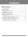
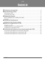
TABLE OF CONTENTS
■ Cautions for safety .................................................................................................3
■ Part Description ......................................................................................................6
Parts of a CNU..........................................................................................................6
CNU connection........................................................................................................7
■ Wiring Diagram ......................................................................................................8
Multi V SUPER(PLUS) & MPS PRODUCT...............................................................8
Connection................................................................................................................9
■ Network Interface Connection.............................................................................11
Dip Switch Configuration.........................................................................................11
■ CNU setup method................................................................................................12
Connect with the PC...............................................................................................12
Set the PC environment for CNU IP setting............................................................13
CNU Setup Configuration .......................................................................................18
■ CNU Normal operation condition confirmation .................................................19
Hardware operation condition confirmation ............................................................19
LAN communication condition confirmation ...........................................................19
485 Communication condition confirmation............................................................19

Cautions for safety
Installation Manual 3
ENGLISH
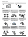
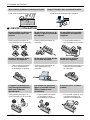
You should always request
product installation to our
Service Center or to
installation expert agency.
Use specified parts.
When reinstalling an existing
installed product, request it to
our Service Center or to
installation expert agency.
• Otherwise it may cause
fire hazard, electric shock,
explosion, injury or
damage.
• Or else it may cause fire
hazard, electric shock,
explosion, injury, damage
and trouble failure.
• Otherwise it may cause fire
hazard, electric shock,
explosion, injury or damage.
Don’t keep or use ignitable gas or any other
flammable material in vicinity of the product.
Don’t disassemble, repair and modify the
product at your will.
• Otherwise it may cause fire hazard and
product trouble failure.
• Or else it may cause fire hazard and electric
shock.
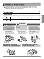
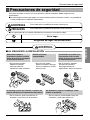
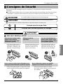
Cautions for safety
To prevent injury to the user or other people and property damage, the following instructions must be
followed.
■ Incorrect operation due to ignoring instruction will cause harm or damage. The seriousness is
classified by the following indications.
This symbol indicates the possibility of death or serious injury.
This symbol indicates the possibility of injury or damage to properties only.
■ Meanings of symbols used in this manual are as shown below.
Be sure not to do.
Be sure to follow the instruction.
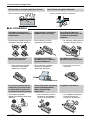
■ WHEN INSTALLING
SPECIFIED
PA RT S
Benzene
Ether
Thinner

Cautions for safety
4 CNU
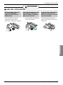
Don’t install it where rain falls on. Don’t install it in humid place.
• Otherwise it may cause product failure. • Otherwise it may cause product failure.
Don’t change or extend
electric supply wire at your
will.
Don’t let there exist fire heat
near the product.
Don’t use heat equipment
near the electricity supply
line.
• Or else it may cause fire
hazard and electric shock.
• Otherwise it may cause fire
hazard.
• Or else it may cause fire
hazard and electric shock.
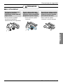
Don’t spill water into interior
of the product.
Don’t put heavy material upon
electricity supply chord.
Don’t put heavy material
upon the product.
• Otherwise it may cause
electric shock and product
failure.
• Or else it may cause fire
hazard and electric shock.
• Or else it may cause
product trouble failure.
Always request to our Service
Center or installation expert agency
in such case as the product has
been submerged under water.
Child or the old and the weak
shall use it under custody of
patron.
Don’t give impact to the
product.
• Or else it may cause fire
hazard and electric shock.
• Otherwise it may cause
safety accident or product
failure.
• If the product is impacted,
it may cause product
trouble failure.
■ WHEN USING

Cautions for safety
Installation Manual 5
ENGLISH
Don’t clean the product with
strong detergent of solvents
but only use soft cloth.
If water has been smeared
on electric charge part, use
it after removing water.
Don’t let metallic products
of necklace, coin, key, watch
etc. touch the battery
terminal.
• Or else it may cause fire
hazard and product
deformation.
• Or else it may cause
product failure.
• Or else it may cause product
failure and injury.
■ WHEN USING
W
a
x
Thinner

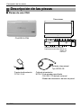
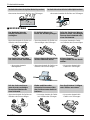
Part Description
Part Description
6 CNU
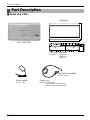
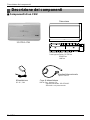
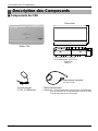
■ Parts of a CNU
200.0
120.0
7.5
20.0
35.0
55.0
Dimension
CNU CONT BOX
Input voltage : DC9V 2.0A
In/out port : RS232 1ea
RS485 1ea
LAN 1ea
Power supply
DC 9V , 2.0A
Power cord
NOTE : AC input spec.
- 100~250 VAC universal input
- Desktop style or wall plug style
International standard
IEC320 C8 type
LGAP

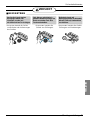
Part Description
Installation Manual 7
ENGLISH
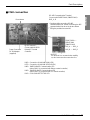
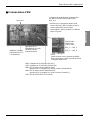
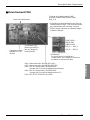
■ CNU connection
RS-485 Communication Terminal
Connect with PMNFP14A0 (PMNFP14A1) :
BUS_A, B
• Cautions while connecting RS-485
communication line : When connecting the 485
communication line do as the picture below
using the provided core and tie.
Power Connector
DC 9V Adaptor
(supplied)
PQNFG14B0 ----
PMNFP14A0
(PMNFP14A1)
Reset button
• NOTICE
this terminal is for communication stability
so, don’t remove and connect other line
RJ45 Connector :
Connect with HUB OR
Deluxe/PC Central
Controller
L06D: Connection of LAN H/W (LINK LED)
L07D: Connection of LAN H/W LED(DUPLEX)
L08D: 10MEGA BASE Communication LED
(when CNU II is connected with Deluxe central controller)
L09D: 100MEGA BASE Communication LED
(when CNU II is connected with PC central controller)
L10D: COLLISION DETECTOR LED
BUS_A ---- BUS_A
BUS_B ---- BUS_B

Wiring Diagram
8 CNU
ON
L1 2 3 4
KSDO4H
CNU PCB
BUS_A
BUS_A
BUS_B
BUS_B
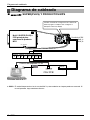
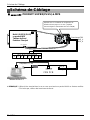
CNU Connection
DC 9V adaptor connection
PC Central controller
MULTI V OUTDOOR TERMINAL BLOCK
DC 9V
ABEFCD
VCC GND
CN_CENTRAL
Multi-V SUPER
(PLUS) or MPS product
Outdoor main PCB
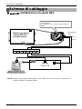
Please refer to network interface setting method on
the 11 page.
It explains about how to set PI 485(M) dip switch.
■ SUPER(PLUS) & MPS PRODUCT
Wiring Diagram
❈ NOTICE : Use of terminal block in case of Multi V and other models may or may not be needed.
If it is not present, make direct connections.

Wiring Diagram
Installation Manual 9
ENGLISH
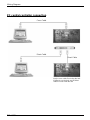
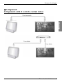
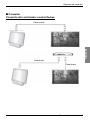
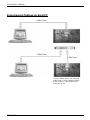
■ Connection
Delux
e central contr
oller connection
Cross Cable
Direct Cable
Direct Cable

Wiring Diagram
10 CNU
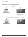
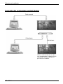
PC central controller connection
Cross Cable
Direct Cable
Direct Cable
Use the cross cable if not using the hub.
If willing to use the hub, use the direct
cable to connect with the hub

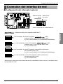
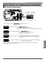
Network Interface Connection
Installation Manual 11
ENGLISH
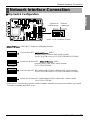
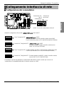
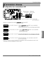
■ Dip Switch Configuration
Network Interface Connection
ON
L1 2 3 4
KSDO4H
ON KSDO 4H
ON KSDO4H
ON KSDO4H
ON KSDO4H
ON KSDO4H
Selection air-
conditioner type
Selection
network type
* LGAP : LG Air conditioner Protocol
& MPS MULTI Products Configuration Methods
& MPS
Inverter Product + Without LGAP central controller
Ex) DCC(PQCSW series) or PCC(PQCSS501A0/PQCSS502A0)
1 ON, Al others OFF:
MPS Multi Standard Product + Without LGAP central controller
Ex) DCC(PQCSW series) or PCC(PQCSS501A0/PQCSS502A0)
2 ON, All others OFF:
Multi Standard Product + With LGAP central controller
Ex) PCC(PQCSS513A0)
2 and 4 ON, All others OFF:
Inverter Product + With LGAP central controller
Ex) PCC(PQCSS513A0)
1 and 4 ON, Al others OFF :
& MPS
* Please refer the corresponding Central Controller installation manual if you want to know whether your Central
Controller is compatible with LGAP or not.

12 CNU
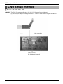
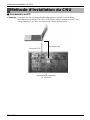
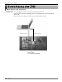
CNU setup method
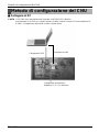
■ Connect with the PC
CNU setup method
❈ NOTICE : The CNU IP is automatically set-up 192.168.1.101 following factory shipment.
Do not set-up the CNU IP if wanting to use the PC Central Control without changing the CNU IP or
Deluxe central controller connection
LAN connection
RS22 connection
Connect Power
DC 9V Adaptor(supplied)

CNU setup method
Installation Manual 13
ENGLISH
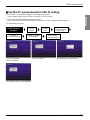
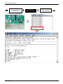
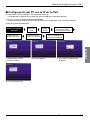
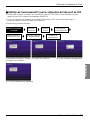
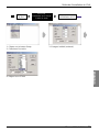
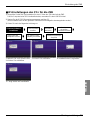
■ Set the PC environment for CNU IP setting
1) Check CNU , and connect between PC and CNU by 232 cable.
If your computer doesn't have 232port, Use USB to 232 Port cable.
2) Start up the RS232 Monitoring Program on the PC.
(You can download the RS232 Monitoring Program from LG air conditioner global website.)
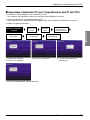
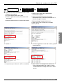
3) Follow below procedure.
Install Teraterm
program
Select
serial
Change
port
1.Select language
2.Click Continue
3.Click Continue 4.Installing step of program
5.Finishing step of the installation
Change IP address
And Gateway
Click the
PCB’
s Reset button
Recheck the
Changed DATA
Serial port
Setup to change
baud rate

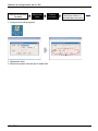
CNU setup method
14 CNU
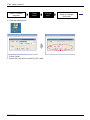
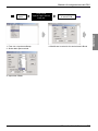
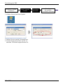
Install Teraterm
program
Select
serial
Change
port
Serial port
Setup to change
boud rate
1. Select Serial
2. Reset the Port which is used by 232 cable.
1. Click the starting icon

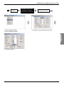
CNU setup method
Installation Manual 15
ENGLISH
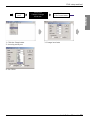
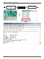
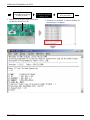
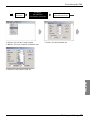
Change
port
Serial port
Setup to change
boud rate
1. Click the Setup button
2. choosing serial port
3. Change boud rate
4. Set 57600
Click the
PCB’s Reset button

CNU setup method
16 CNU
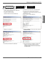
Serial port
Setup to change
boud rate
1. Click the PCB's reset button
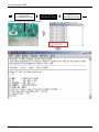
1. type the character “C”
Change IP address
And Gateway
Click the
PCB’s Reset button

CNU setup method
Installation Manual 17
ENGLISH
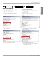
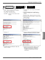
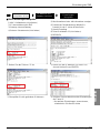
1. type character “2” 2. type IP address 192.168.1.102 , and
Click ENTER key
3. Check the changed IP address
4. If you finish setting, Type “9”
* Follow upper procedure and Change other
setting items properly
Change IP address
And Gateway
Click the
PCB’
s Reset button
Recheck the
Changed DATA
■ Check CNU Setting data
1) MAC : Device Address (Don't change)
2) IP : CNU internet address
3) Gateway : internet Gateway
4) Subnet : Subnet mask (Don't change)
5) Load all info : total information
6) Central Controller Protocol : Select protocol '0' or
'1', refer next page.
7) Daytime Setting
8) Telnet Port : 23 (Don't change)
9) EXIT

CNU setup method
18 CNU
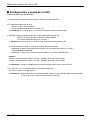
■ CNU Setup Configuration
Press the number which it wants changing
1. MAC address (Don't change)
00.E0.91.0F.XX.XX is an item which is specific value
2. IP : IP set up menu
- Use CNU IP set or change
- Default value in factory is 192.168.1.101
❈ Notice : Incase using private IP, Consult with network manager
3. GATEWAY : network gateway IP set up menu
- Use CNU network gateway IP set or change
- Default value in factory is 192.168.1.1
❈ Notice : Incase using private IP, Consult with network manager
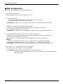
6. Central controller Protocol(1:LGAP,0:OLD) : LGAP selection menu
• select '0' : in using Deluxe central controller or PC central controller without
LGAP(PQCSS501A0/PQCSS502A0)
• select '1' : in using PC central controller with LGAP(PQCSS513A0)
example)
- Central Controller Protocol(LGPA:1, OLD:0) ➔ After input 0, press ENTER
- Central Controller Protocol(LGAP:1, OLD:0) ➔ After input 1, press ENTER
❈ Notice : When the network set goes wrong and does not become the communication
7. Number 1,4,5,7,8 items are not setup Menu.
So, Don't change default value
❈ Notice : After all of settings are finished
You should escape set up mode by typing '9' otherwise, The CNU will not operate normally

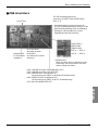
CNU Normal operation condition confirmation
Installation Manual 19
ENGLISH
■ Hardware operation condition confirmation
CNU Normal operation condition confirmation
1) Check CNU LED1 is continuously blinking : 485 communication LED
2) Check L06D, L07D LEDs are Lighting : LAN CABLE connection confirmation LED
3) Check L09D,L08D blinking : LAN communication condition confirmation LED
L08D blinking : connected Deluxe central controller(10M BPS)
L09D blinking : connected PC(100M BPS)
❈ Notice : If the LAN cable is are not connected between PC(or DCC) and CNU then the LED6D,7D are not light
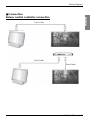
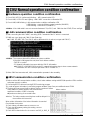
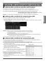
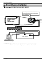
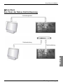
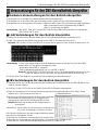
■ LAN communication condition confirmation
1) After connecting the LAN CABLE, executing, DOS Command of the PC which is connected
2) PING test : type 'ping' and 'CNU IP' then Enter key
ex) PING 192.168.1.101 (The CNU IP will be different which is real set ,so type real CNU IP)
❈ Notice : The response time will be different to system condition
If ping test is fail(request tine out) then check below condition
- CNU IP is correct?
- PC Network information has same with the CNU IP information
ex) If CNU IP is 192.168.1.101 then the PC network information does to have a same network
information 192.168.1.XXX(except same CNU IP number or 1 )
3) When PING test executes well, LAN communication operates in the normality.
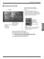
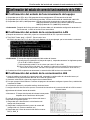
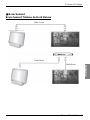
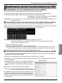
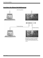
■ 485 Communication condition confirmation
1) Before confirm 485 communication condition, check indoor address setting and 485 G/W operation LED's condition
and power resource condition.
2) Connecting RS232 cable and running RS232 monitoring program
3) In order to appear information in monitoring program window, Setup Com port and Baud rate to 57600.
4) The data will come up and it will be able to confirm a number of indoor
Setup address of indoor appears, 485 communication
operational condition of CNU is normality
ex) number monitoring of connected indoor
❈ Notice : The indoor number searching time could be delayed in in
the condition which searches
When neither information of the indoor information is searched
Check below check points
1) Check Indoor unit address are set correct or not
2) Check the 485 gateway setting (s/w setting, connect
connection..etc.)
3) Check 485 communication line is correct or not BUS_A, BUS_B
Indoor number

Memo
20 CNU
La pagina sta caricando ...
La pagina sta caricando ...
La pagina sta caricando ...
La pagina sta caricando ...
La pagina sta caricando ...
La pagina sta caricando ...
La pagina sta caricando ...
La pagina sta caricando ...
La pagina sta caricando ...
La pagina sta caricando ...
La pagina sta caricando ...
La pagina sta caricando ...
La pagina sta caricando ...
La pagina sta caricando ...
La pagina sta caricando ...
La pagina sta caricando ...
La pagina sta caricando ...
La pagina sta caricando ...
La pagina sta caricando ...
La pagina sta caricando ...
La pagina sta caricando ...
La pagina sta caricando ...
La pagina sta caricando ...
La pagina sta caricando ...
La pagina sta caricando ...
La pagina sta caricando ...
La pagina sta caricando ...
La pagina sta caricando ...
La pagina sta caricando ...
La pagina sta caricando ...
La pagina sta caricando ...
La pagina sta caricando ...
La pagina sta caricando ...
La pagina sta caricando ...
La pagina sta caricando ...
La pagina sta caricando ...
La pagina sta caricando ...
La pagina sta caricando ...
La pagina sta caricando ...
La pagina sta caricando ...
La pagina sta caricando ...
La pagina sta caricando ...
La pagina sta caricando ...
La pagina sta caricando ...
La pagina sta caricando ...
La pagina sta caricando ...
La pagina sta caricando ...
La pagina sta caricando ...
La pagina sta caricando ...
La pagina sta caricando ...
La pagina sta caricando ...
La pagina sta caricando ...
La pagina sta caricando ...
La pagina sta caricando ...
La pagina sta caricando ...
La pagina sta caricando ...
La pagina sta caricando ...
La pagina sta caricando ...
La pagina sta caricando ...
La pagina sta caricando ...
La pagina sta caricando ...
La pagina sta caricando ...
La pagina sta caricando ...
La pagina sta caricando ...
La pagina sta caricando ...
La pagina sta caricando ...
La pagina sta caricando ...
La pagina sta caricando ...
La pagina sta caricando ...
La pagina sta caricando ...
La pagina sta caricando ...
La pagina sta caricando ...
La pagina sta caricando ...
La pagina sta caricando ...
La pagina sta caricando ...
La pagina sta caricando ...
La pagina sta caricando ...
La pagina sta caricando ...
La pagina sta caricando ...
-
 1
1
-
 2
2
-
 3
3
-
 4
4
-
 5
5
-
 6
6
-
 7
7
-
 8
8
-
 9
9
-
 10
10
-
 11
11
-
 12
12
-
 13
13
-
 14
14
-
 15
15
-
 16
16
-
 17
17
-
 18
18
-
 19
19
-
 20
20
-
 21
21
-
 22
22
-
 23
23
-
 24
24
-
 25
25
-
 26
26
-
 27
27
-
 28
28
-
 29
29
-
 30
30
-
 31
31
-
 32
32
-
 33
33
-
 34
34
-
 35
35
-
 36
36
-
 37
37
-
 38
38
-
 39
39
-
 40
40
-
 41
41
-
 42
42
-
 43
43
-
 44
44
-
 45
45
-
 46
46
-
 47
47
-
 48
48
-
 49
49
-
 50
50
-
 51
51
-
 52
52
-
 53
53
-
 54
54
-
 55
55
-
 56
56
-
 57
57
-
 58
58
-
 59
59
-
 60
60
-
 61
61
-
 62
62
-
 63
63
-
 64
64
-
 65
65
-
 66
66
-
 67
67
-
 68
68
-
 69
69
-
 70
70
-
 71
71
-
 72
72
-
 73
73
-
 74
74
-
 75
75
-
 76
76
-
 77
77
-
 78
78
-
 79
79
-
 80
80
-
 81
81
-
 82
82
-
 83
83
-
 84
84
-
 85
85
-
 86
86
-
 87
87
-
 88
88
-
 89
89
-
 90
90
-
 91
91
-
 92
92
-
 93
93
-
 94
94
-
 95
95
-
 96
96
-
 97
97
-
 98
98
-
 99
99


LG PQNFG14B0.ENCXLEU Manuale del proprietario
- Tipo
- Manuale del proprietario
- Questo manuale è adatto anche per
in altre lingue
Documenti correlati
Altri documenti
-
Sony PXW X320 Guida utente
-
Wolf CNG 10 - 35 Installation Instructions Manual
-
Neff T56TT60N0 Manuale del proprietario
-
Whirlpool WTE25112 W Guida utente
-
Siemens IQ700 EX801LYC1E Manuale del proprietario
-
Bosch SERIE 8 PIV875DC1E Manuale del proprietario
-
-
VESTEL AC11 Series Installation Manualline
-
ABB CM-MPS.21 Istruzioni per l'uso
-
Philips Xenium 9@9 Guida utente