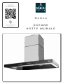
ROBLIN OCEANE 900 VERRE INOX SM Manuale del proprietario
- Categoria
- Cappe da cucina
- Tipo
- Manuale del proprietario

CONCEPTION
FABRICATION
FRANÇAISE
Notice
OCEANE
HOTTE MURALE

F SOMMAIRE
RACCORDEMENT ÉLECTRIQUE
CONSEILS D’INSTALLATIONS
POSE DE L’APPAREIL
FONCTIONNEMENT
CONSEILS D’UTILISATIONS
ENTRETIEN
GARANTIE ET SERVICE APRÈS-VENTE
REMARQUES
D INHALT
NETZANSCHLUSS
MONTAGEHILFEN
MONTAGE DES GERÄTES
BETRIEB DES GERÄTES
NUTZUNG
WARTUNG UND REINIGUNG
GARANTIE UND KUNDENDIENST
WICHTIGE HINVEISE
E SUMARIO
CONEXION ELECTRICA
CONSEJOS DE INSTALACION
INSTALACION DEL APARATO
FUNCIONAMIENTO
CONSEJOS DE UTILIZACION
MANTENIMIENTO
GARANTIA Y ASSISTENCIA TECNICA
NOTA
GB CONTENTS
ELECTRICAL WIRING
INSTALLATION ADVICE
FITTING THE APPLIANCE
OPERATION
USEFUL HINTS
MAINTENANCE
GUARANTEE AND AFTER-SALES-SERVICES
REMARKS
I CONTENUTI
COLLEGAMENTO ELETTRICO
CONSIGLI DI INSTALLAZIONE
POSA DELL’ APPARECCHIO
FUNZIONAMENTO
CONSIGLI DI UTILIZZO
MANUTENZIONE
GARANZIA ED ASSISTENZA TECNICA
NOTE
NL INHOUD
ELECTRISCHE BEDRADING
MONTAGE AANWIJZING
AANSLUITEN VAN HET APPARAAT
FUNKTIONEREN
GEBRUIKSADVIES
ONDERHOUD
AFTER SALES SERVICE
OPMERKINGEN

1
F
Nous vous remercions de la confiance que vous nous avez accordée en choisissant un appareil de la
gamme ROBLIN.
Celui-ci a fait l’objet de toute notre attention dans sa conception et sa réalisation.
Afin qu’il vous donne entière satisfaction, nous vous recommandons de lire avec attention cette notice qui
vous expliquera comment l’installer, l’utiliser et l’entretenir dans les meilleures conditions.
La présente notice d’emploi vaut pour plusieurs versions de l’appareil. Elle peut contenir des descriptions
d’accessoires ne figurant pas dans votre appareil
1 RACCORDEMENT ÉLECTRIQUE.
• La hotte est équipée d’un cordon d’alimentation de type HO5VVF 3 x 0,75 mm² comportant une
fiche normalisée 10/16 A avec système de mise à la terre.
Mode de protection : classe I. Tension d’alimentation : 220-240 V mono - 50Hz / 220 V - 60Hz.
Vérifier que la tension du secteur est identique aux valeurs indiquées sur la plaque signalétique à
l’intérieur de la hotte
• Si la hotte est raccordée directement sur le réseau sans sa fiche, un interrupteur omnipolaire avec
une ouverture de contact de 3 mm doit être installé avant la hotte. Le fil de terre (Jaune / vert) ne doit
pas être interrompu par cet interrupteur.
2 CONSEILS D’INSTALLATION.
• Respecter le diamètre de sortie de l’appareil : la hotte ne doit en aucun cas être raccordée à un
conduit de ventilation mécanique contrôlée (V.M.C.).
• Lorsqu’on évacue l’air vicié dans un conduit d’évacuation, veiller à ce que celui-ci ne soit pas déjà
exploité à véhiculer des gaz ou fumées provenant d’appareils alimentés par une énergie autre qu’élec-
trique.
• Positionner le plan de cuisson au plus près de l’évacuation et éviter la formation de coudes sur la
gaine, afin de réduire au maximum les pertes de charges
• Dans tous les cas d’installation, veiller au bon renouvellement d’air de la cuisine. Penser à ef-
fectuer une ou des entrées d’air par une grille de section égale
ou supérieure au diamètre du tuyau
d’évacuation, afin de ne pas mettre la cuisine en dépression
• Prévoir une aération suffisante lorsqu’un appareil de cuisson ou autre utilise simultanément l’air
ambiant de la pièce où est installée la hotte.
• La dépression maximum crée dans la pièce doit être inférieur à 0.04 mbar, ce qui évite un retour de
gaz de combustion.
• L’appareil doit être positionné de telle façon que la fiche d’alimentat on soit accessible.
• Cet appareil ne doit pas être utilisé par des personnes (y compris les enfants) ayant des capacités
psychiques, sensorielles ou mentales réduites, ni par des personnes n’ayant pas l’expérience et la
connaissance de ce type d’appareils, à moins d’être sous le contrôle et la formation de personnes res-
ponsables de leur sécurité.
• Les enfants doivent être surveillés pour s’assurer qu’ils ne jouent pas avec l’appareil.

2
F
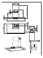
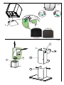
3 POSE DE L’APPAREIL.
Montage et raccordement doivent être réalisés par un installateur* qualié.
(*) Le non-respect de cette condition entraîne la suppression de la garantie du constructeur et
tout recours en cas d’accident.
Attention: prendre bien soin d’employer les chevilles adaptées au support, se renseigner au près
des fabricants, effectuer un scellement si nécessaire. La société décline toute responsabilité en
cas d’accrochage défectueux dû au perçage et chevillage.
1) Tracer sur la paroi une verticale jusqu’au plafond à l’emplacement de la hotte au centre de la zone
prévue pour le montage de la hotte Fig.1;2, (1). Cette ligne sert pour aligner verticalement les
différentes parties.
2) Positionner le support de conduit Fig. 1;2, (2), centré sur la verticale à 1 à 2 mm du plafond ou de la
limite supérieure et marquer sur la paroi les deux alésages du support. Effectuer sur la paroi deux trous
avec un foret Ø 8 mm. Fixer le support de conduit (2) à l’aide des vis (12a) 4.2 x 44,4 et des chevilles
fournies.Puis positionner et fixer comme indiqué Fig. 2 le second support (2) .
3) Définir la position des trous de fixatio Fig. 1,2, (1):
Marquer un point sur la ligne verticale à une distance du plan de cuisson de :
d = 962 mm (mesure sans crédence).
La hauteur H est la hauteur minimum en mm du plan de cuisson au bas de la hotte (3).
Tracer sur le point marqué une ligne horizontale parallèle au plan de cuisson. Effectuer sur la paroi les
deux trous (1) avec un foret Ø 8 mm . Insérer les chevilles et visser les vis 4.2 x 44,4 fournies en
laissant un espace de 5-6 mm nécessaire pour l’accrochage du corps de la hotte Fig. 3a. Il sera
possible d’ef-fectuer de petits ajustages au moyen des vis de réglage de la hotte (Voir Montage du
corps de la hotte). La hotte peut avoir une excursion maximum de 16 mm.
Crédence (Option) : La hauteur de la hotte par rapport au plan de cuisson est déterminée, dans ce cas
par la hauteur de la crédence et par l’éventuel dosseret du plan de travail. La crédence doit être montée
avant le corps de la hotte et si l’on désire la fixer contre le mur tant en haut qu’en bas, il es nécessaire
de la positionner à la juste hauteur. Etant donné qu’il s’agit d’une opération compliquée, elle doit être
effectuée exclusivement par l’installateur de la cuisine ou par du personnel compétent connais-sant
toutes les dimensions finales des meubles
4) Montage du corps de la hotte : Avant d’entreprendre l’installation, il est nécessaire de régler les
étriers du support en tournant dans le sens des aiguilles d’une montre les vis de réglage (Vr) jusqu’en fi
de course Fig. 3b. Accrocher le corps (5) sur les deux vis (12b) précédemment installées Fig. 3. Mettre
la hotte de niveau en tournant les vis de réglage (Vr) et compléter le serrage des vis (12b).
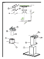
5) Raccordement
• Pour la version Evacuation Extérieure :
a- Mettre en place le clapet anti-retour (8) sur la sortie de l'appareil (6) et raccorder le tuyau flexible Fig.
5 à l’évacuation extérieure et la sortie de l’appareil (6). Fixer l’ensemble à l’aide de colliers ou de ruban
adhésif appropriés.
• Pour la version Recyclage:
a- Fixer le support (4) du déflecteur sur la fixation du haut de conduit, le déflecteur est fixé avec
mêmes vis que le support de haut de conduit Fig.7, (2). Inserer latéralement les rallonges raccord (G) sur
le déflecteur (R). S'assurer que la sortie des rallonges raccord se trouve au niveau des ouies du conduit
aussi bien en horizontal qu'en vertical.
b- Installer un tuyau de diamètre approprié (Non fourni) entre la sortie de l’appareil et à l’entrée du
déflecteur. Fixer l’ensemble à l’aide de colliers ou de ruban adhésif appropriés.
c- Ouvrir le panneaux mobile et enlever le filtre métallique et placer la cartouches à charbon actif dans
son logement en exerçant une pression sur les languettes (A) Fig. 4.

3
F
5.1) Ouvrir le reflecteur et enlever le filtre à graisse et s'assurer que le connecteur du cable Fig. 4
d'alimentation soit bien branché dans la prise du moteur . Raccorder électriquement la hotte (Voir
paragraphe Raccordement Electrique) et vérifier le bon fonctionnement de l’éclairage, du moteur et du
changement des vitesses d’aspiration.
5.2) Conduit supérieur : Elargir légèrement les 2 bords latéraux Fig.7, (7a) et les accrocher derrière les
support (2), refermer jusqu'à la butée. Fixer latéralement au support (2) à l'aide des 2vis (12c) 2.9 x 9.5
fournies.
5.3) Conduit inférieur : Elargir légèrement les 2 bords latéraux Fig.7, (7b) et les accrocher entre le
conduit supérieur et la paroi; refermer jusqu'à la butée.

4
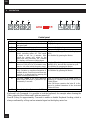
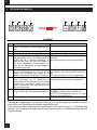
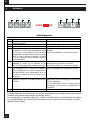
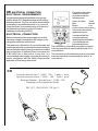
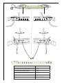
4 FONCTIONNEMENT
F
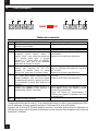
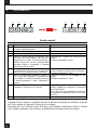
Tableau des commandes
Touche
Fonction Afficheur
A Allume et éteint le moteur d’aspiration à la
dernière vitesse utilisée
Affiche la vitesse réglée.
B Diminue la vitesse de service. Les segments allumés diminuent.
C Augmente la vitesse de service. Les segments allumés augmentent.
D
Met en marche la vitesse intensive de
n’importe
quelle vitesse, même à
moteur éteint ; cette vitesse est temporisée
à 6 minutes, après quoi, le système
retourne à la vitesse réglée au préalable.
Idéale pour faire face à des émissions
maximales de fumées de cuisson.
I clignote et les segments sur l’afficheur sont
tous allumés.
Appuyer sur la touche pour désactiver.
E
Met en marche
le moteur à une vitesse per-
mettant une aspiration de 100 m
3
/h
pendant 10 minutes toutes les heures
durant 24h; après quoi le moteur s’arrête.
24 s’affiche et les segments qui sont tous allu-
més sur l’afficheur s’éteignent un à un de fa-
çon cyclique.
Appuyer sur la touche pour désactiver.
F Active l’arrêt automatique après un délai de
30’. Idéale pour éliminer complètement les
odeurs résiduelles. Peut être activée depuis
n’importe quelle position, appuyer sur la tou-
che ou éteindre le moteur pour désactiver la
fonction.
Le symbole d’une Horloge qui clignote
s’affiche.
Appuyer sur la touche pour désactiver.
G Appuyer sur la touche pendant environ 2 se-
condes pour rétablir
l’alarme signalant la
saturation des filtres à l’état initial
Après 100 heures de fonctionnement, le sym-
bole Goutte s’affiche pour signaler la satura-
tion des filtres métalliques.
Après 200 heures de fonctionnement, C
s’affiche pour signaler la saturation des filtres
au charbon actif.
H Allume et éteint l’éclairage.
Commande de blocage du clavier : il est possible de bloque le clavier, par exemple pour effec-
tuer le nettoyage du verre, quand le moteur et l’éclairage de la hotte sont éteints.
Appuyer sur la touche F (Retard) pendant environ 5 secondes pour activer ou désactiver le
blocage du clavier, qui est toujours confirmé par un bip sonore et une animation sur la barre du
moteur de l’afficheur.
B
A
D
C
E
H
G
F

5
5 CONSEILS D’UTILISATION.
• Pour obtenir une efficacité maximum d’absorption des fumées ou des vapeurs, faire fonctionner
l’appareil 5 minutes environ avant et après la cuisson des aliments; La première vitesse est conseillée
pour les cuissons à feu doux et pour les sauces. La deuxième pour les cuissons soutenues, grillades et
friteuses. La troisième est indiquée pour les cuissons à forte émanation de graisses et vapeur.
• IMPORTANT . NE JAMAIS FLAMBER DE METS AU DESSOUS DE L’APPAREIL
Ne laissez jamais de flammes libres sous la hotte en fonctionneme t.
• Les fritures nécessitent une surveillance permanente, l’huile surchauffée pouvant s’enflamme .
6 ENTRETIEN.
Déconnecter le câble d’alimentation pour toute intervention électrique.
L’appareil a été conçu pour faciliter au maximum les opérations d’entretien, synonyme de bon fonctionne-
ment et rendement de l’appareil dans le temps.
• Nettoyage des ltres métalliques.
Il est indispensable de procéder à un NETTOYAGE PÉRIODIQUE de ces filtres à la main (avec un détergent
liquide à l’eau tiède et rinçage) ou au lave- vaisselle (tous les deux mois environ pour une utilisation normale).
• Carrosserie.
Nettoyer régulièrement celle-ci en utilisant des produits détergents, non abrasifs et une éponge légèrement
humide. N’utilisez jamais d’éponges ou de chiffons trempés
N’introduisez aucun objet, ni les mains dans l’ouverture servant à l’évacuation de l’air
• Conduit d’évacuation.
Vérifier tous les 6 mois le bon écoulement de l’air vicié.
Observer les prescriptions réglementaires locales concernant l’évacuation de l’air vicié.
• (A1) Éclairage.
Avant toute intervention sur l’appareil, mettre l’interrupteur d’allumage des lampes en position éteinte.
Ne pas dépasser la puissance prescrite et ne pas changer de type de lampe.
7 GARANTIE ET SERVICE APRÈS-VENTE.
• En cas d’anomalie de fonctionnement, prévenez votre installateur qui devra vérifier l’appareil et son
raccordement.
• Dans le cas où un composant électrique viendrait à être endommagé, celui-ci ne peut être remplacé
que par un atelier de réparation reconnu par le fabricant, car des outils spéciaux sont nécessaires.
• Débrancher complètement l’appareil.
• Exigez toujours l’utilisation de pièces de rechange d’origine. La non observation de cette prescription
peut compromettre la sécurité de l’appareil.
• Lors de la commande de pièces détachées, rappeler le numéro de l’appareil inscrit sur la plaque
signalétique située à l’intérieur de la hotte.
• Seule la facture d’achat de l’appareil fera foi pour l’application de la garantie contractuelle.
Cette garantie ne couvre pas les consommables comme :
- L’éclairage : lampes incandescentes, halogènes ...
- Les filtres
8 REMARQUES.
Cet équipement est conforme à la norme européenne sur la basse tension 2006/95/CE relative à la
F

6
F
sécurité électrique et aux normes européennes: 2004/108/CE relative à la compatibilité électromagnétique
et 93/68 relative au marquage CE.
Lorsque ce symbole
d’une poubelle à roue barrée est attaché à un produit, cela signifie que le
produit est couvert par la Directive Européenne 2002/96/EC. Votre produit est conçu et fabriqué avec
des matériaux et des composants de haute qualité, qui peuvent être recyclés et utilisés de nouveau.
Veuillez vous informer du système local de séparation des déchets électriques et électroniques. Veuillez
agir selon les règles locales et ne pas jeter vos produits usagés avec les déchets domestiques usuels.
Jeter correctement votre produit usagé aidera à prévenir les conséquences négatives potentielles contre
l’environnement et la santé humaine.
9 CONSEILS POUR L’ECONOMIE D’ENERGIE.
Lorsque vous commencez à cuisiner, activer la hotte à la vitesse minimum pour contrôler l’humidité et
éliminer les odeurs de cuisine.
Utilisez la vitesse intensive lorsque cela est strictement nécessaire.
Augmentez la vitesse de la hotte seulement lorsque la quantité de vapeur le requiert.
Veillez à ce que le ou les filtres de la hotte soient toujours propres, afin d’optimiser l’éfficacité
anti-graisse et anti-odeurs.

7
GB
Thank you for buying a ROBLIN product which has been manufactured to the highest quality standards
to meet your requirements.
We recommend you carefully read this booklet in which you will find instructions for installation, hints for
use and maintenance.
The Instructions for Use apply to several versions of this appliance. Accordingly, you may find descrip-
tions of individual features that do not apply to your specific appliance
1 ELECTRICAL
• This cooker hood is fitted with a -core mains cable with a standard 10/16A earthed plug.
• Alternatively the hood can be connected to the mains supply via a double-pole switch having 3mm
minimum contact gap on each pole.
• Before connecting to the mains supply ensure that the mains voltage corresponds to the voltage on
the rating plate inside the cooker hood.
• Technical Specification: oltage 220-240 V, single phase ~ 50 Hz / 220 V - 60Hz.
2 INSTALLATION ADVICE
• It is a possible fire risk if the hoo is not sited as recommended.
• To ensure the best results, the cooking fumes should be able to rise naturally towards the inlet grilles
on the underside of the cooker hood and the cooker hood should be positioned away from doors and
windows, which will create turbulence.
• Ducting
• If the room where the hood is to be used contains a fuel-burning appliance such as a central heating
boiler then its flue must be of the room sealed or balanced flue typ
• If other types of flue or appliances are fitted
ensure that there is an adequate supply of fresh air to
the room. Ensure the kitchen is fitted with an airbrick, which should have a cross-sectional measurement
equivalent to the diameter of the ducting being fitted, if not large .
• The ducting system for this cooker hood must not be connected to any existing ventilation system,
which is being used for any other purposes or to a mechanically controlled ventilation ducting.
• The ducting used must be made from fire retardant materials and the correct diameter must be used,
as incorrect sized ducting will affect the performance of this cooker hood.
• When the cooker hood is used in conjunction with other appliances supplied with energy other than
electricity, the negative pressure in the room must not exceed 0.04 mbar to prevent the fumes from
combustion being drawn back into the room.
• The appliance is for domestic use only and should not be operated by children or people who are
infirm without supervision
• This appliance must be positioned so that the wall socket is accessible.
• This appliance is not intended for use by persons (including children) with reduced physical, sensory
or mental capabilities, or lack of experience and knowledge, unless they have been given supervision or
instruction concerning use of the appliance by a person responsible for their safety.
Children should be supervised to ensure that they do not play with the appliance.
3 FITTING
Any permanent electrical installation must comply with the latest regulations concerning this type of instal-
lation and a qualifi d electrician must carry out the work. Non-compliance could cause serious accidents
or injury and would deem the manufacturers guarantee null and void.
IMPORTANT - The wires in this mains lead are coloured in accordance with the following code :

8
GB
green / yellow : earth blue : neutral brown : live
As the colours of the wires in the mains lead of this appliance may not correspond with the coloured
markings identifying the terminals in your plug, proceed as follows.
- The wire which is coloured green and yellow must be connected to the terminal in the plug which is
marked with the letter E or by the earth symbol or coloured green or green and yellow.
- The wire which is coloured blue must be connected to the terminal which is marked with the letter N
or coloured black.
- The wire which is coloured brown must be connected to the terminal which is marked with the letter
L or coloured red.
ATTENTION: Do not forget to use adequate plugs to the support brackets. Enquire after the manu-
facturers. Do an embedding if necessary. The manufacturer accepts no responsibility in case of a
faulty hanging due to the drilling and the setting up of plugs.
1) Draw a vertical line onto the wall from the centre of the cooking appliance up to the ceilling, using a
spirit level and a marker pen as illustrated in Fig. 1;2 (1). This is to ensure the correct align-ment of the
chimney hood.
2) Place one of the brackets (2)
on the wall about 1 or 2 mm from the ceiling or from the upper limit,
aligning its centre (notches) on the vertical line. Mark the two eyelet holes of the bracket onto the wall.
Place the other bracket (2) on the wall, aligning it with the vertical line. Drill the holes for the 2 fixing
brackets using an 8 mm masonry bit. Fix the chimney brackets (2) using the 4.2 x 44.4 mm screws and
rawl plugs supplied.
3) Drilling fixing holes (1) Fig. 1;2:
Mark a point on the vertical line at a distance from the cooking appliances of:
d = 962 mm (Measurement without splashback).
The distance H is the minimum height in mm from the cooking appliances to the bottom edge item 3
ofthe front panel of the hood.
At the point marked, draw a horizontal line parallel to the cooking appliances. Drill two holes (1) in the
wall using an 8 mm drill bit and insert the rawl plugs and screws into the holes (1) (4.2 x 44.4 screws).
Fix the screws, leaving a space of 5-6 mm required to hook up the canopy Fig. 3a. Small adjustments
can be made using the hood adjustment screws (see Fitting the canopy). The hood should have a
maximum excursion of 16 mm.
Splashback (optional): When a splashback is to be fitted, the distance between the hood and the cooking
appliances will be determined by the height of the splashback and whether or not there is a raised
back on the worktop. The splashback is to be installed before installing the canopy. If the
splashback is to be fixed to the wall using both the top and bottom fixing holes, Care must be taken
to ensure that the splashback is fitted at the correct height before fixing the base units or at least the
worktop covering them. As this is a complex operation, it should only be undertaken by the technician
installing the kitchen units or by a competent person who knows the final dimensions of the units.
4) Fixing the canopy: Before starting to fix the canopy it will be necessary to adjust the support
brackets by turning the adjustment screws (Vr) in a clockwise direction until their reach their limit Fig.3.
Hook the canopy onto the two size 4.2 x 44.4 screws (12b) fitted as described above Fig.3. Level the
hood by turning the adjustment screws and then locking the screws (12b)
5) Ducting:
The hood is more effective when used in the extraction mode (ducted to the outside). When the cooker
hood is ducted to the outside, charcoal lters are not required.The ducting used must be 150 mm (6
INS), rigid circular pipe and must be manufactured from re retardant material, produced to BS.476
or DIN 4102-B1. Wherever possible use rigid circular pipe which has a smooth interior, rather than
the expanding concertina type ducting.
Maximum length of ducting run:
- 4 metres with 1 x 90° bend.

9
GB
- 3 metres with 2 x 90° bends.
- 2 metres with 3 x 90° bends.
The above assumes our 150 mm (6 INS) ducting is being installed. Please note ducting components and
ducting kits are optional accessories and have to be ordered, they are not automatically supplied
with the chimney hood.
IN THE EXTRACTION MODE:
a. Place the anti-backflow flat (8) over the round outlet (6) and connect the ducting 150mm (6 INS)
over the round outlet (6) on top of the canopy and secure the connections with appropriate clamping
rings or adhesive tape Fig. 5.
IN THE RECIRCULATION MODE:
a. Fit the recirculation spigot bracket (4) onto the upper chimney wall bracket using the same fixin
screws Fig.7 (
2). Put the spigot (R) into the spigot bracket (4)• Insert the connection extension
pieces laterally (G) in the spigot. Make sure that the outlet of the extension pieces (G) is horizontally
and vertically aligned with the chimney outlets.
b. Connect the ducting 150mm (6 INS) not provided between motors (6) and the recirculation spigot
and secure the connections with appropriate clamping rings or adhesive tape.
c. Open the deflector and remove the grease filter and insert the charcoal filter into the base of the
motor housing and secure the filter with two metal securing straps item (A) as illustrated in Fig. 4.
5.1) Open the deflector and remove the grease filter (see paragraph Maintenance) being sure tha
the connector of the feeding cable is correctly inserted in the socket placed on the side of the fan
Fig.4 . Before fitting the chimney to the canopy make the electrical connection as described in the
section titled ELECTRICAL. When the electrical connection has been made, test the lights and the
fan motor.
5.2) Upper chimney stack
Slightly widen the two sides of the upper chimney stack Fig.7 (7a) and hook them behind the
brackets item 2 making sure that they are well seated.
Secure the sides to the upper bracket using the 2 screws (12c) (2,9 x 9,5) supplied.
5.3) Lower chimney stack
•Slightly widen the two sides of the chimney stack Fig. 7 (7b) and hook them between the upper
chimey stack and the wall, making sure that they are well seated.

10
4 OPERATION
GB
Control panel
Button Function Display
A Turns the suction motor on and off at the
last speed used.
Displays the speed set.
B Decreases the working speed. Decreases the lighted segments.
C Increases the working speed. Increases the lighted segments.
D Activates intensive speed from any other
speed, including motor off. This speed
is timed to run for 6 minutes, after
which the system will return to the
speed that was previously set. Suitable
for dealing with severe cooking fumes.
I flashes and the segments on the Display are
all lit.
It is disabled by pressing the Button.
E Starts the motor at a speed that allows a
suction of 100 m
3
/h for 10 minutes every
hour for 24h, after which the motor stops.
Displays 24 and the segments on the Display,
initially all lit, turn off one at a time in cycle.
It is disabled by pressing the Button.
F Activates automatic switch-off with a 30’
delay. Suitable to complete elimination of
residual odours. Can be activated from any
position, it is deactivated by pressing the
button of turning the motor off.
Displays a flashing Clock symbol.
It is disabled by pressing the Button.
G Performs a Reset of the Filter saturation
alarm when the button is pressed for ap-
proximately 2 seconds.
After 100 hours operation the Drop symbol is
displayed to indicate saturation of the Metal
Grease Filters.
After 200 hours operation the letter C is dis-
played to indicate saturation of the Activated
Charcoal Filters.
H Turns the Lighting System on and off.
Keyboard Lock Command: it is possible to lock the keyboard, for example when cleaning the
Glass, when the Hood Motor and Lights are turned off.
Press F (Delay) for approximately 5 seconds to enable or disable Keyboard Locking, which is
always confirmed by a Beep and an animated signal on the display motor bar.
B
A
D
C
E
H
G
F

11
5 USEFUL HINTS
• To obtain the best performance we recommend you to switch ‘ON’ the cooker hood a few minutes (in
the boost setting) before you start cooking and you should leave it running for approximately 15 minutes
after finishing
• IMPORTANT: NEVER DO FLAMBÉ COOKING UNDER THIS COOKER HOOD
• Do not leave frying pans unattended during use as over-heated fat and oil might catch re.
• Do not leave naked ames under this cooker hood.
• Switch ‘OFF’ the electric and gas before removing pots and pans.
• Ensure heating areas on your hotplate are covered with pots and pans when using the hotplate
and cooker hood simultaneously.
6 MAINTENANCE
Before carrying out any maintenance or cleaning isolate the cooker hood from the mains supply.
The cooker hood must be kept clean; a build up of fat or grease may cause a fire hazard
Casing
• Wipe the cooker hood frequently with a clean cloth, which has been immersed in warm water contain-
ing a mild detergent and wrung out.
• Never use excessive amounts of water when cleaning particularly around the control panel.
• Never use scouring pads or abrasive cleaners.
• Always wear protective gloves when cleaning the cooker hood.
Metal Grease Filters : The metal grease filters absorb grease and dust during cooking in order to keep
clean the cooker hood inside. The grease filters should be cleaned once a month or more frequently if
the hood is used for more than 3 hours per day.
To remove and replace the metal grease lters
• Remove the metal grease filters one at a time by releasing the catches on the filters; the filters can
now be removed.
• The metal grease filters should e washed, by hand, in mild soapy water or in a dishwasher.
• Allow to dry before replacing.
Active Charcoal Filter : The charcoal filter cannot be cleaned. The filter should be replaced at least
every three months or more frequently if the hood is used for more than three hours per day.
To remove and replace the lter
• Remove the metal grease filters
• Press against the two retaining clips, which hold the charcoal filter in place and this will allow the filte
to drop down and be removed.
• Clean the surrounding area and metal grease filters as directed above
• Insert the replacement filter and nsure the two retaining clips are correctly located.
• Replace the metal grease filters
Extraction tube : Check every 6 months that the dirty air is being extracted correctly. Comply with local
rules and regulations with regard to the extraction of ventilated air.
Lighting (A1)
: If the lamp fails to function check to ensure it is fitted correctly into the holder. If lamp
failure has occurred then it should be replaced with identical replacement.
Do not replace with any other type of lamp and do not t a lamp with a higher rating.
7 GUARANTEE AND AFTER SALES SERVICE
• In the event of any malfunction or anomaly, notify your tter who will have to check the ap-
pliance and its connection.
GB

12
• In the event of damage to the mains supply cable, this can only be replaced by at approved repair
centre appointed by the manufacturer who will have the required tools and equipment to carry out any
repairs properly. Repairs carried out by other persons will invalidate the guarantee.
• Use only genuine spare parts. Should these warnings fail to be observed it could affect the safety of
your cooker hood.
• When ordering spare parts quote the model number and serial number written on the rating plate,
which is found on the casing behind the grease filters inside the hood
• Proof of purchase will be required when requesting service. Therefore, please have your receipt
available when requesting service as this constitutes the date from which your guarantee commenced.
This Guarantee does not cover :
- Damage or calls resulting from transportation, improper use or neglect, the replacement of any light
bulbs or filters or removable parts of glass or plastic
These items are considered to be consumable under the terms of this guarantee.
8 REMARKS
This appliance complies with European regulations on low voltages Directive 2006/95/CE on electrical
safety, and with the following European regulations: Directive 2004/108/CE on electromagnetic compat-
ibility and Directive 93/68 on EC marking.
When this crossed-out wheeled bin symbol
is attached to a product it means the product is cov-
ered by the European directive 2002/96/EC.Your product is designed and manufactured with high quality
materials and components, which can be recycled and reused.Please inform yourself about the local
separate collection system for electrical and electronic product. Please act according to your local rules
and do not dispose of your old products with your normal household waste. The correct disposal of your
old product will help prevent potential negative consequences for the environment and human health.
GB
9 ENERGY SAVING TIPS.
When you start cooking, switch on the range hood at minimum speed, to control moisture and remove
cooking odor.
Use boost speed only when is strictly necessary.
Increase the range speed only when the amount of vapor makes it necessary.
Keep range hood filter(s) clean to optimize grease and odor efficiency.

13
D
Wir danken Ihnen für Ihre Kaufentscheidung und das Vertrauen, welches Sie mit dem Kauf dieses
ROBLIN-Produktes bewiesen haben.
Dieses Gerät wurde mit einem hohen Maß an Kreativität entwickelt und mit
größter Sorgfalt gefertigt.
Um volle Zufriedenheit mit Leistung und Funktion dieser Dunstesse zu erlangen und zu erhalten, emp-
fehlen wir dringend, sowohl die Montage-anweisung sorgfältig zu beachten und danach zu arbeiten als
auch die “ Gebrauchs- und Wartungshinweise ” aufmerksam zu lesen und anzuwenden.
Diese Gebrauchsanleitung gilt für mehrere Geräte-Ausführungen. Es ist möglich,
dass einzelne Ausstattungsmerkmale beschrieben sind, die nicht auf Ihr Gerät zutreffen.
1 NETZANCHLUSS
• Die Dunstabzugshaube ist mit einer Anschlußleitung der Art HO5VVF 3 x 0,75 mm
2
, die einen
Schutzstecker 10 / 16 A enthält, ausgestattet. Das entspricht Schutzklasse 1.
Nennspannung : 220 - 240 V - Wechselstrom : 50 Hz / 220 V - 60 Hz.
• Es ist sicherzustellen, daß die Netzspannung den Anschlußwerten auf dem Typenschild im Inneren
der Dunstesse entspricht.
• Beim Anschluß der Dunstesse an das Wechselstromnetz ist ein zweipoliger Schalter mit einem
Öffnungsweg von wenigstens 3 mm für jeden Pol zwischenzuschalten.
2 MONTAGEHILFEN
• Der A
ußendurchmesser am Gebläseabgang des Gerätes ist für die Wahl des Abluft-Rohrsystems zu
berücksichtigen : Die Dunstesse darf keinesfalls an eine Entlüftungsleitung mit Unterdruck angeschlossen
werden. Die Abluft darf nicht in einen Schornstein geleitet werden, der für die Abgase von Koch- oder
Heiz-Geräten, (Kohle-, Öl-, oder Gas-Öfen oder -Herde) benutzt wird.
• Die Kochstelle (und damit auch die Dunstesse) so planen und installieren, daß möglichst kurze
Wege für eventuelle Abluft-Rohrleitungen erreicht werden. (so wenige Umlenkungen [90°-Bögen] wie
möglich! Keine Querschnittsverengungen!
• Die gute Erneuerung der Luft in der Küche ist zu beachten. Denken Sie daran, einen oder mehrere
Lufteintritte durch eine Öffnung, die den gleichen Durchmesser hat wie die Abluftleitung, vorzusehen.
• Sorgen Sie für eine ausreichende Zuluft, wenn ein Koch- oder anderes Gerät die Luft des Raumes,
in dem die Dunstesse eingebaut ist, gleichzeitig verwendet. Ein gefahrloser Betrieb ist möglich, wenn
bei gleichzeitigem Betrieb von Dunstesse und Feuerstätte im Raum ein Unterdruck von höchstens 0.04
mbar erreicht wird und ein Rücksaugen der Feuerstättenabgase vermieden wird.
Das Gerät muß so installiert werden, daß der Geräte-Stecker leicht erreichbar ist.
• Dieses Gerät darf nicht von Personen, auch Kindern, mit verminderten psychischen, senso-
rischen und geistigern Fähigkeiten, oder von Personen ohne Erfahrung und Kenntnisse benutzt werden,
sofern sie nicht von für ihre Sicherheit verantwortlichen Personen beaufsichtigt und beim Gebrauch des
Geräts angeleitet werden.
Kinder dürfen sich nicht unbeaufsichtigt in der Nähe des Geräts aufhalten und auf keinen Fall mit dem
• Gerät spielen.
3 MONTAGE DES GERÄTES
Montage und Anschluß müssen von einem qualifizierten Installateur* durchgeführt werden
(*) Wenn diese Bedingung nicht eingehalten wird, wird die Garantie des Herstellers, sowie jeder
Anspruch im Falle eines Unfalles aufgehoben.

14
D
Achtung ! Bitte beachten Sie bei der Montage das Gewicht der kompletten Dunstesse. Die Tragfä-
higkeit der Decke oder alternativ der Trägerplatte für diese Zugbelastung muss vor der Montage
geprüft und gegebenenfalls durch die Anbringung von geeigneten Befestigungs-oder Stabilisie-
rungselementen hergestellt werden. Kann eine hinreichende Tragfähigkeit nicht sichergestellt
werden, ist von einer Montage abzusehen.
1) An der Wand eine vertikale Linie (1) Fig. 1;2 bis zur Decke zeichnen (in der Mitte des Bereiches,
indem die Haube montiert werden soll), die dem vertikalen Ausrichten der Einzelteile dient.
2) Einen der beiden Bügel (2) Fig. 1;2 cirka 1 oder 2 mm von der Decke oder der oberen Begren-
zung an die Wand legen und seinen Mittelpunkt (Einschnitte) auf die vertikale Linie ausrichten.
Die beiden ösenförmigen Bohrlöcher des Bügels an der Wand markieren. Den zweiten Bügel 2 an
die Wand legen und auf die vertikale Linie ausrichten, . Den jeweiligen Mittelpunkt der
ösenförmigen Bohrlöcher des Bügels an der Wand markieren.
3) Festlegung der Fixierlöcher (1) Fig. 1;2:
Einen Punkt auf der vertikalen Linie kennzeichnen, der folgenden Abstand zur Kochmulde aufweist:
d = min. 962 (Maß ohne Rückwand).
Das Maß H ist die Mindesthöhe in mm von der Kochmulde zur unteren Frontkante (3).
Beim markierten Punkt eine horizontale Linie aufzeichnen, die parallel zur Kochmulde verläuft. Mit einem
Bohrer Ø8 mm zwei Löcher (1) in die Wand bohren Fig. 3a und die Dübelbzw. die Feststellschrauben
bei den Bohrungen (1) anbringen (Schrauben zu 4,2 x44,4). Beim Anziehen der Schrauben einen
Freiraum von 5-6 mm belassen, der zum Einhaken des Haubenkörpers notwendig ist. Geringfügige
Änderungen können mit Hilfe der Stellschrauben der Haube (siehe Montage des Haubenkörpers)
erfolgen. Die maxi-male Haubenweg beträgt 16 mm.
Rückwand (Optional): Der Abstand der Haube von der Kochmulde wird in diesem Fall von der Höhe der
Rückwand und des eventuell anzubringenden Aufsatzes an der Arbeitsplatte bestimmt. Die Rückwand
wird vor Montage des Haubenkörpers angebracht; will man die Rückwandoben und unten mit der Wand
verschrauben, muss sie auf die gewünschte Höhe ausgerichtet werden, bevor der Unterschrank oder die
Arbeitsplatte montiert wird. Da es sich hierbei um einen relativ komplizierten Vorgang handelt, sollte er
nur vom Küchenmontagepersonal oder von fachlich geschulten Personen, die die Endmasse der Möbel
genau kennen, durchgeführt werden.
4)
Montage des Haubenkörpers bevor mit der Installation begonnen wird, müssen di
e Haltebügel Vrre-
guliert werden,indem man die Stellschrauben bis zum Anschlag im Uhrzeigersinn dreht Fig. 3:
a)Die Haube bei den beiden zuvor angebrachten Schrauben (12b) (4,2 x 44,4) einhaken Fig. 3.
b)Die Haube mit Hilfe der Stellschrauben ausrichten und die Schrauben festziehen.
5) Anschluss für Abluft- oder Umluftbetrieb:
• Abluftbetrieb
a- Die Rückstauklappe (8) am Gerätsausgang anbringen (6). Der Schlauch an den Ge-
rätsausgang anbringen Fig. 5, (6) und dann an den Gerätsausgang anschliessen. Beim
Anschluss die Ringe und den passenden Kleber benutzen wieder schließen.
• Umluftbetrieb
a- Den Umluftadapter (R) an den Oberkamin hängen, der Umluftadapter wird mit den gleichen
Schrauben als die Schrauben für die Oberkaminstütze Fig. 7 (2
) befestigt. Die Verlängerungen
(G) beim Anschluss (R) seitlich einfügen. Überprüfen, ob die Verlängerungen (G) mit den
entsprechenden Kaminstützen sowohl horizontal wie auch vertikal übereinstimmen.
b- Ein Verbindungsrohr mit anpassenden Durchmesser (nicht beigefügt) an die Lufteintritt der Um-
luftadapter und an den Gebläseausgang (6) anschliessen. Beim Anschluss die Ringe und den
passenden Kleber benutzen.
c- Die Metal-Fettfilter abnehmen. Die Stütze der Aktivkohle-Filter befestigen und einen Druck auf die
Dörner (A) Fig .4 ausüben, um die Aktivkohle-Filterkassette aufzustellen.

15
D
5.1) Entfernen Sie die Fettfilter (s.
Abschnitt „Wartung“) und versichern Sie sich, daß die
Kabelverbindung in die Steckdosedes Gebläses einwandfrei eingesteckt wird. Den Netzanschluss
der Haube vollziehen (siehe Abschnitt Netzanschluss) und den guten Betrieb der Beleuchtung,
des Motors sowie als die Veränderung der Gebläseleistung prüfen.
5.2) Oberer Kaminteil: Die beiden seitlichen Schenkel leicht Fig.7 (7a) auseinanderbiegen, hinter
den Bügeln 2 einhängen und bis zum Anschlag wiederschließen. Bei den Bügeln 2 mit Hilfe der 2
mitgelieferten Schrauben (12c) fixieren. Überprüfen, ob die Verlängerungen mit den
entsprechenden Kaminstützen übereinstimmen.
5.3) Unterer Kaminteil: Die beiden seitlichen Schenkel des Kaminteils leicht Fig. 7 (7b) aus-
einanderbiegen, zwischen dem oberen Kaminteil und der Wand einhängen und bis zum Anschlag
wieder schließen.

16
4 BETRIEB DES GERATES
D
Schalttafel
Taste
Funktion Display
A Schaltet den Motor der Absauganlage bei der
zuletzt verwendeten Geschwindigkeit ein und
aus.
Zeigt die eingestellte Geschwindigkeit an.
B Vermindert die Betriebsgeschwindigkeit. Die leuchtenden Segmente nehmen ab.
C Erhöht die Betriebsgeschwindigkeit. Die leuchtenden Segmente nehmen zu.
D Aktiviert von jeder Geschwindigkeit aus, auch
bei abgestelltem Motor, die Intensivgeschwin-
digkeit, die auf 6 Minuten zeitgeregelt ist.
Nach Ablauf dieser Zeit kehrt das System zu
der zuvor eingestellten Geschwindigkeit zu-
rück. Für die Beseitigung von sehr intensiven
Kochdünsten geeignet.
I blinkt und alle Segmente auf dem Display
leuchten.
Wird durch Drücken der Taste ausgeschaltet.
E Aktiviert den Motor bei einer Geschwindigkeit,
die eine Absaugleistung von 100 m
3
/h für die
Dauer von 10 Minuten jede Stunde für 24
Stunden, nach dessen Ablauf hält der Motor an.
Zeigt 24 an und alle auf dem Display angezeig-
ten Segmente erlöschen allmählich nacheinan-
der.
Wird durch Drücken der Taste ausgeschaltet.
F Aktiviert das automatische Ausschalten mit
einer Verzögerung von 30’. Ermöglicht die
Beseitigung von Restgerüchen. Kann von jeder
Position aus eingeschaltet werden und wird
durch Drücken der Taste oder abstellen des
Motors ausgeschaltet.
Zeigt das Symbol einer blinkenden Uhr an.
Wird durch Drücken der Taste ausgeschaltet.
G Führt durch ca. 2 Sekunden langes Drücken der
Taste ein Reset des Filtersättigungsalarms aus.
Nach 100 Betriebsstunden zeigt das Symbol
Tropfen die Sättigung der Metallfilter an.
Nach 200 Betriebsstunden zeigt C die Sätti-
gung der Aktivkohlefilter an.
H Schaltet die Beleuchtung ein oder aus.
Steuerbefehl Tastatursperre: Die Tastatur lässt sich, z.B. zur Reinigung der Scheiben, sperren,
wenn Motor und Beleuchtung der Haube ausgeschaltet sind.
Zum Aktivieren oder Deaktivieren der Tastatursperre die Taste F (Delay) ca. 5 Sekunden lang
drücken. Der Vorgang wird immer durch einen Piepton und die Motorbalkenanzeige auf dem
Display bestätigt.
B
A
D
C
E
H
G
F

17
5 NUTZUNG
• Um ein optimales Absaugen der Kochschwaden zu erzielen, wird empfohlen, das Gerät vor dem
Kochen einzuschalten und nach dem Kochen noch einige Zeit nachlaufen zu lassen. Für die Speisen,
die wenig Dampf entwickeln, verwenden Sie vorzugsweise die kleine Geschwindigkeit.
• WICHTIG : NIEMALS UNTER DEM GERÄT FLAMBIEREN.
Niemals eine große Flamme bei eingeschalteter Dunstesse unbedeckt lassen.
Wenn der Topf weggenommen wird, ist die Flamme abzuschalten oder für einen kurzen Zeitraum auf
kleinste Stellung zu drehen, trotzdem aber unbedingt im Auge zu behalten.
Frittiergeräte, die unter der Dunstesse betrieben werden, sind während der gesamtem Betriebsdauer zu
beaufsichtigen: überhitztes Öl kann sich entzünden und die Haube in Brand setzen.
6 WARTUNG UND REINIGUNG
Vor jedem Eingriff im Gerät immer den Netzstecker ziehen, oder die Sicherung herausdrehen bzw. die
Stromzufuhr unterbrechen.
Bei dem Einbau des Gerätes wurde besonders die Wartungs-Freundlichkeit berücksichtigt.
• Herausnehmen des Metalllters :
Es ist unerläßlich, diese Filter REGELMÄßIG falls notwendig auch in kurzen Intervallen, mit der Hand
(
lauwarmes W
asser mit Waschmittel
und Spülen) oder in der Geschirrspülmaschine zu REINIGEN. Diese
Maßnahmen vermindern die Brandgefahr (starke Fettrückstände sind leicht brennbar).
• Gehäuse.
Keine nassen Tücher für die Reinigung der Oberflächen der Dunstesse verwenden. Es sollen nur
milde Reinigungsmittel und leicht feuchte Tücher verwendet werden. Keine Gegenstände in die
Luftaustritts-öffnung stecken. Nicht in die Luftaustrittsöffnung greifen.
• Abluftleitung:
Kontrollieren Sie von Zeit zu Zeit, daß der Luftkanal nicht verstopft ist. Diese Prüfung muß halbjährlich
durchgeführt werden. Die behördlichen Anforderungen, für die Ableitung der Abluft, sind zu berück-
sichtigen.
• (A1) Beleuchtung:
Bei Leuchtmittel-Wechsel in jedem Fall den Schalter der Beleuchtung ausschalten.
Die Art des Leuchtmittels nicht wechseln. Leistung nicht überschreiten.
7 GARANTIE UND KUNDENDIEST
• Bei Versagen des Gerätes benachrichtigen Sie Ihren Installateur, der das Gerät und seine Instal-
lation überprüfen wird.
• Wenn die Geräte-Zuleitung beschädigt wurde, darf diese nur von einer Reparaturwerkstatt
ersetzt werden, die vom Hersteller anerkannt ist, weil Sonderwerkzeuge nötig sind. Haube komplett
abschalten.
• Stets nur Original-Ersatzteile verwenden.
• Sollte diese Vorschrift nicht eingehalten werden, könnte die Sicherheit des Gerätes beeinträchtigt
werden. Außerdem erlischt die Garantie.
• Bei der Bestellung von Ersatzteilen geben Sie bitte die Nummer des Gerätes, die sich auf dem
D

18
Typenschild hinter dem Gehäuse befindet, an
• Für die Anwendung der vertraglicher Garantie wird nur die Einkaufsrechnung des Gerätes ver-
bindlich anerkannt. Von der Garantieleistung ausgenommen sind:
- Die Beleuchtung : Klassik - und Halogenbeleuchtung
- Die Filter (Die Filter sind als Verbrauchsgüter anzusehen).
8 WICHTIGE HINWEISE
Dieses Gerät entspricht den europäischen Niederspannungsrichtlinien 2006/95/EWG zur elektrischen
Sicherheit, den europäischen Richtlinien 2004108/EWG zur elektromagnetischen Verträglichkeit und den
Richtlinien 93/68/EWG zur CE Kennzeichnung.
Das Symbol
auf dem Produkt oder seiner Verpackung weist darauf hin, dass dieses Produkt nicht
als normaler Haushaltsabfall zu behandeln ist, sondern an einem Sammelpunkt für das Recycling von
elektrischen oder elektronischen Geräten abgegeben werden muss. Durch Ihren Beitrag zum korrekten
Entsorgen dieses Produktes schützen Sie die Umwelt und die Gesundheit Ihrer Mitmenschen. Umwelt
und Gesundheit werden durch falsches Entsorgen gefährdet. Weitere Informationen über das Recycling
dieses Produktes erhalten Sie von Ihrer kommunalen Behörde, den örtlichen Müllentsorgungsunterneh-
men oder von Ihrem Fachhändler.
D
9 TIPS VOOR ENERGIEBESPARING.
Schakel de afzuigkapop de laagste snelheid in wanner u met koken begint om de vochtigheidsgraad
te regelen en kookluchtjes te verwijderen.
Gebruik de hoogste snelheid alleen wanner dit bestist noodzakelijk is.
Verhoog de snelheid van de afzuigkap alleen wanner de hoeveelheid damp dit vereist.
Houd het filter/de filters van de afzuigkap schoon om de vetfilterings-en geurfilteringefficiëntie te
optimaliseren.
La pagina si sta caricando...
La pagina si sta caricando...
La pagina si sta caricando...
La pagina si sta caricando...
La pagina si sta caricando...
La pagina si sta caricando...
La pagina si sta caricando...
La pagina si sta caricando...
La pagina si sta caricando...
La pagina si sta caricando...
La pagina si sta caricando...
La pagina si sta caricando...
La pagina si sta caricando...
La pagina si sta caricando...
La pagina si sta caricando...
La pagina si sta caricando...
La pagina si sta caricando...
La pagina si sta caricando...
La pagina si sta caricando...
La pagina si sta caricando...
La pagina si sta caricando...
La pagina si sta caricando...
La pagina si sta caricando...
La pagina si sta caricando...
La pagina si sta caricando...
La pagina si sta caricando...
La pagina si sta caricando...
La pagina si sta caricando...
La pagina si sta caricando...
La pagina si sta caricando...
La pagina si sta caricando...
La pagina si sta caricando...
-
 1
1
-
 2
2
-
 3
3
-
 4
4
-
 5
5
-
 6
6
-
 7
7
-
 8
8
-
 9
9
-
 10
10
-
 11
11
-
 12
12
-
 13
13
-
 14
14
-
 15
15
-
 16
16
-
 17
17
-
 18
18
-
 19
19
-
 20
20
-
 21
21
-
 22
22
-
 23
23
-
 24
24
-
 25
25
-
 26
26
-
 27
27
-
 28
28
-
 29
29
-
 30
30
-
 31
31
-
 32
32
-
 33
33
-
 34
34
-
 35
35
-
 36
36
-
 37
37
-
 38
38
-
 39
39
-
 40
40
-
 41
41
-
 42
42
-
 43
43
-
 44
44
-
 45
45
-
 46
46
-
 47
47
-
 48
48
-
 49
49
-
 50
50
-
 51
51
-
 52
52


ROBLIN OCEANE 900 VERRE INOX SM Manuale del proprietario
- Categoria
- Cappe da cucina
- Tipo
- Manuale del proprietario
in altre lingue
- English: ROBLIN OCEANE 900 VERRE INOX SM Owner's manual
- français: ROBLIN OCEANE 900 VERRE INOX SM Le manuel du propriétaire
- español: ROBLIN OCEANE 900 VERRE INOX SM El manual del propietario
- Deutsch: ROBLIN OCEANE 900 VERRE INOX SM Bedienungsanleitung
- Nederlands: ROBLIN OCEANE 900 VERRE INOX SM de handleiding
Documenti correlati
-
ROBLIN OSMOSE VERRE Manuale del proprietario
-
-
-
-
-
-
-
-