
Installation Guide
MHM-97923-PBF, Rev 1.0
April 2020
AMS Asset Monitor
Online Prediction, Protection, and Process Monitor

Copyright
©
2020 by Emerson. All rights reserved.
No part of this publication may be reproduced, transmitted, transcribed, stored in a retrieval system, or translated into any
language in any form by any means without the written permission of Emerson.
Disclaimer
This manual is provided for informational purposes. EMERSON MAKES NO WARRANTY OF ANY KIND WITH REGARD TO THIS
MATERIAL, INCLUDING, BUT NOT LIMITED TO, THE IMPLIED WARRANTIES OF MERCHANTABILITY AND FITNESS FOR A PARTICULAR
PURPOSE. Emerson shall not be liable for errors, omissions, or inconsistencies that may be contained herein or for incidental or
consequential damages in connection with the furnishing, performance, or use of this material. Information in this document is
subject to change without notice and does not represent a commitment on the part of Emerson. The information in this manual is
not all-inclusive and cannot cover all unique situations.
Patents
The product(s) described in this manual are covered under existing and pending patents.
Vermerk zur Installation der Messketten in explosionsgefährdeter Umgebung.
Soll die Messkette in explosionsgefährdeter Umgebung installiert werden, so ist auf die Einhaltung der in der
Gebrauchsanweisung enthaltenen Installationshinweise zu achten. Sollten dabei sprachliche Schwierigkeiten
auftreten, wenden Sie sich bitte an die Herstellerfirma, sie wird Ihnen eine Übersetzung der relevanten Artikel in der
Landessprache des Verwendungslandes zukommen lassen.
Nota fuq l−installazzjoni tal−ktajjen tal−kejl f’ambjent esplożiv
Jekk il−katina tal−kejl suppost li tigi installata f’ambjent esplożiv, hu importanti li ssegwi l−istruzzjonijiet pertinenti
tal−manwal.Jekk issib xi diffikultà bil−lingwa, jekk joghgbok ikkuntattja lill−manifattur biex tikseb traduzz-joni tal
−paragrafi rilevanti fil−lingwa mehtiega.
Anmärkning beträffande installation av mätkedjorna i explosionsfarlig miljö.
Ska mätkedjan installeras i explosionsfarlig miljö, måste de anvisningar följas som ges i instruktionsboken
beträffande installationen. Skulle därvid språkproblem uppstå, ber vi dig kontakta det tillverkande företaget som
då kommer att sända dig en översättning av de relevanta artiklarna på användningslandets språk.
Opomba za namestitev merilne verige v eksplozivno ogroženem okolju
Èe se merilna veriga namešèa v eksplozivno ogroženem okolju, je potrebno upoštevati namestitvena opozorila, ki
so v Navodilih za uporabo. Èe se pri tem pojavijo jezikovne težave, se posvetujte z izdelovalcem; poslali vam bodo
prevod ustreznih èlankov v jeziku države, kjer se naprava uporablja.
Záznam k inštalácii meracích reťazcov vo výbušnom prostredí
Ak má byť merací reťazec inštalovaný vo výbušnom prostredí, treba dbať na dodržiavanie pokynov k inštalácii,
uvedených v návode na použitie. V prípade, že by sa pritom vyskytli jazykové problémy, obráťte sa prosím na
výrobcu, ktorý Vám zašle preklad relevantných èlánkov v jazyku Vašej krajiny.
Nota referente à instalação de cadeias de agrimensor em ambientes potencialmente explosivos
Caso a cadeia de agrimensor deva ser instalada em um ambiente potencialmente explosivo, é imprescindível
observar e cumprir as indicações de instalação das instruções de serviço. Caso tenha dificuldades idiomáticas,
queira entrar em contato com a firma produtora, esta poderá enviar−lhe uma tradução dos capítulos mais
importantes no idioma do país onde o produto deverá ser empregado.
Wskazówka dotycząca instalacji łañcuchów mierniczych w otoczeniach zagrożonych eksplozją
Jeœli łañcuch mierniczy ma byæ zainstalowany w otoczeniu zagrożonym eksplozją, należy uwzglêdniæ wskazówki
dotyczące instalacji zawarte w instrukcji obsługi. Jeżeli w trakcie lektury wstąpią jakiekolwiek problemy związane ze
zrozumieniem tekstu, prosimy zwróciæ siê do producenta, który chêtnie przeœle tłumaczenie konkretnego
artykułu w jêzyku danego kraju.
2

Opmerking m.b.t. installatie van elektrische meet circuits in explosiegevaarlijke omgeving
Dient de installatie van elektrische meet circuits in een explosiegevaarlijke omgeving te geschieden, moet men
toezien dat de in de gebruikshandleiding opgenomen installatieinstructies worden nageleefd. Bij taalkundige
problemen gelieve contact op te nemen met de fabrikant, deze zal u vervolgens een vertaling in de taal van het
gebruiksland doen toekomen.
Pastaba dėl matavimo grandinės įrengimo sprogimo atžvilgiu pavojingoje aplinkoje
Jei matavimo grandinė turi būti įrengta sprogimo atžvilgiu pavojingoje aplinkoje, privaloma laikytis vartotojo
instrukcijoje pateiktų įrengimo nurodymų. Jei kiltų sunkumų dėl kalbos, prašome kreiptis į gamintojo įmonę, kuri
pateiks Jums reikiamo skyriaus vertimą į vartotojo valstybės kalbą.
Nota sull’installazione delle catene per misurazione in ambienti a rischio di esplosioni
Nel caso in cui si debbano installare le catene per misurazione in ambienti a rischio di esplosioni, è necessario
attenersi alle avvertenze per l’installazione contenute nelle istruzioni d’uso. Per difficoltà di carattere linguistico,
rivolgetevi alla ditta produttrice. Quest’ultima Vi farà pervenire una traduzione degli articoli rilevanti nella lingua
del paese d’impiego.
Megjegyzės a mėrőláncok robbanásveszėlyes környezetben törtėnő szerelėsėhez.
Ha a mėrőláncot robbanásveszėlyes környezetben kell felszerelni, akkor ügyeljen a Használati útmutatóban közölt
szerelėsi utasítások betartására. Amennyiben nyelvi nehėzsėgek merülnek fel, szíveskedjen a gyártó céghez
fordulni, amely elküldni Önnek a felhasználó ország nyelvėre lefordított, erre vonatkozó cikket.
Remarque concernant l’installation des chaînes de mesure dans un environnement présentant un risque
d’explosion
Si la chaîne de mesure doit être installée dans un environnement présentant un risque d’explosion, il est impératif
de veiller à respecter les consignes d’installation contenues dans les instructions de service. S’il devait ce faisant
surgir des problèmes linguistiques, veuillez vous adresser à la société fabricante: elle vous fera parvenir une
traduction des articles significatifs dans la langue du pays de mise en oeuvre.
Huomautus mittausketjun asentamisesta räjähdysalttiissa ympäristössä
Jos mittausketju tulee asentaa räjähdysalttiissa ympäristössä, on käyttöohjeessa annettuja asennusohjeita
noudatettava. Jos käyttöohjeessa käytetty kieli aiheuttaa ongelmia, kääntykää valmistajayrityksen puoleen. Se
toimittaa käyttöönne tarvittavat artikkelit käyttömaan vir alliselle kielelle käännettynä.
Juhend mõõdukettide ülespanemiseks plahvatusohtlikus piirkonnas.
Kui panna üles mõõdukettid plahvatusohtlikkus piirkonnas, nii tuleb jälgida kasutusjuhendis sisaldatud
instalationimärkmeid. Juhul kui tekkivad raskused keelega, siis pöörduge palun tootja poole. Tootja saadab
emakeelse tõlge vastavalt artiklile ning maale.
Notas sobre la instalación de cadenas de medición en un entorno potencialmente explosivo.
Si ha de instalar la cadena de medición en un entorno potencialmente explosivo, deberá respetar las indicaciones
sobre la instalación, contenidas en el manual de uso. Si surgieran dificultades lingüísticas, póngase en contacto con
la empresa fabricante, que le facilitará una traducción del artículo en la lengua del país donde se emplee.
Note on the installation of the measuring chains in an explosive environment
If the measuring chain is supposed to be installed in an explosive environment, it is important to follow the
pertinent installation instructions in the manual. Should you encounter difficulties with the language, please
contact the manufacturer to obtain a translation of the relevant paragraphs into the language required.
3

Σημεíωση για τηυ εγκατáσταση αλuσíδωυ μέτρησης σε περιβáλλου, στο oπoío uπàρΧει κíυδuυoς έκρηξης
Εáυ η αλuσυδα μέτρησης πρóκειται υα εγκατασταΘεí σε περιβáλλoυ, στo oπoío uπáρΧει κíυδuυoς έκρηξης, πρέπει
υα τηρηΘoúυ oπωσδńπoτε oι oδηγíες εγκατáστασης πoυ περιλαμβáυoυται στις oδηγíες Χρńσης. Εáυ υπáρξouυ
γλωσσικές δuσκoλíες καταυóησης, παρακαλoúμε υα απεuΘuυΘεíτε στηυ κατασκεuáστρια εταιρεíα, η oπoíα Θα
ϕρoυτíσει για τηυ απoστoλń μιας μετáϕρασης τωυ σΧετικωυ áρΘρωυ στη γλωσσα της Χωρας Χρńσης.
Info vedrørende installation af målekæderne i eksplosionstruede omgivelser
Hvis målekæden skal installeres i eksplosionstruede omgivelser, skal installationsanvisningerne i brugsanvisningen
følges. Hvis der i denne forbindelse opstår sproglige problemer, bedes De henvende Dem til produktionsfirmaet,
som så vil sørge for, at De modtager en oversætelse af den relevante artikel på Deres sprog.
Poznámka k instalaci mĕřicích řetězců v prostředí s nebezpečím výbuchu.
Když má být měřicí řetězec (sestávající z čidla a konvertoru) instalován v prostŕedí s nebezpečím výbuchu, tak je
třeba respektovat instalační pokyny, které jsou součástí návodu k upotřebení. Kdyby při tom došlo k jazykovým
potížím, tak prosíme kontaktujte výrobní firmu, která Vám relevantní článek zašle v jazyku krajiny použití.
Piezīme par mērīšanas ķēžu instalēšanu sprādziena bīstamās zonās.
Ja mērīšanas ķēde jāuzstāda sprādzienbīstamā zonâ, ir jāievēro lietošanas instrukcijā dotie instalēšanas norādījumi.
Ja rodas kādas valodas grūtības, lūdzu griezieties pie izgatavotāja firmas, kas Jums nosūtīs nozīmīgâko nodaļu
tulkojumus lietotāja valsts valodā.
Emerson
epro GmbH
Jöbkesweg 3
48599 Gronau
Germany
T +49 2562 709 0
F +49 2562 709 401
www.Emerson.com
4

Contents
Chapter 1 General.......................................................................................................................... 9
1.1 About this manual............................................................................................................................ 9
1.2 Symbols......................................................................................................................................... 10
1.3 Liability and guarantee................................................................................................................... 11
1.4 Incoming goods inspection............................................................................................................ 11
1.5 Technical support...........................................................................................................................11
1.6 Storage and transport.....................................................................................................................12
1.7 Disposal of the device.....................................................................................................................12
1.8 China RoHS Compliance................................................................................................................. 12
1.9 Installation awareness.................................................................................................................... 13
Chapter 2 Safety instructions....................................................................................................... 15
2.1 Using the device............................................................................................................................. 15
2.2 Owner's responsibility.....................................................................................................................15
2.3 Radio interference..........................................................................................................................15
2.4 ESD safety...................................................................................................................................... 16
2.5 Important information about hazardous live voltages.................................................................... 16
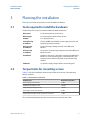
Chapter 3 Planning the installation.............................................................................................. 17
3.1 Tools required to install the hardware.............................................................................................17
3.2 Torque limits for mounting screws................................................................................................. 17
3.3 Wiring guidelines............................................................................................................................18
3.3.1 Wiring overview.......................................................................................................................... 19
3.4 Select a mounting place................................................................................................................. 21
Chapter 4 Installing AMS Asset Monitor hardware........................................................................23
4.1 CSA – General safety.......................................................................................................................23
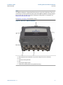
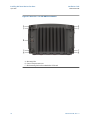
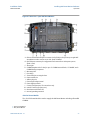
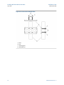
4.2 About the AMS Asset Monitor hardware......................................................................................... 23
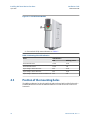
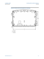
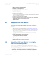
4.3 Position of the mounting holes.......................................................................................................28
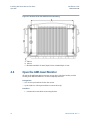
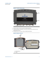
4.4 Open the AMS Asset Monitor..........................................................................................................30
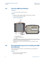
4.5 Close the AMS Asset Monitor..........................................................................................................32
4.6 Recommended sequence for installing the AMS Asset Monitor...................................................... 32
4.7 Mount the AMS Asset Monitor........................................................................................................33
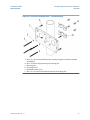
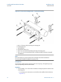
4.8 Mount the AMS Asset Monitor by using the universal mounting bracket.........................................33
4.9 Replace the cable inlet dust caps.................................................................................................... 37
4.10 Grounding....................................................................................................................................38
4.11 Network connection.....................................................................................................................40
4.11.1 Permissible network topology................................................................................................... 42
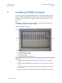
Chapter 5 Installing CHARMs hardware........................................................................................47
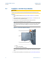
5.1 Install the +24 V DC Power Module.................................................................................................50
Installation Guide Contents
MHM-97923-PBF April 2020
MHM-97923-PBF, Rev. 1.0 v

5.1.1 Connect the power supply...........................................................................................................51
5.2 Install an VI Piezo CHARM...............................................................................................................51
5.2.1 Connect the sensor wiring...........................................................................................................52
5.3 Install a DO 24 V DC High-Side CHARM...........................................................................................53
5.3.1 Connect the output signal wiring.................................................................................................53
5.3.2 Connect the relay output wiring.................................................................................................. 55
5.4 Install a DI 24 V DC Low-Side Sens CHARM......................................................................................56
5.4.1 Connect the input signal wiring................................................................................................... 57
5.5 Install a AI 4 to 20 mA CHARM........................................................................................................ 58
5.5.1 Connect the input signal wiring – self-powered........................................................................... 59
5.5.2 Connect the input signal wiring – loop-powered......................................................................... 60
5.6 Install a RTD CHARM.......................................................................................................................61
5.6.1 Connect the sensor wiring...........................................................................................................62
5.7 Install a Thermocouple/mV input CHARM.......................................................................................63
5.7.1 Connect the sensor wiring...........................................................................................................64
5.8 Install the Address Plug...................................................................................................................65
5.9 Label the installed CHARMs............................................................................................................ 66
5.10 CHARM Protection Cover..............................................................................................................68
Chapter 6 Removing CHARMs hardware.......................................................................................69
6.1 Remove a CHARM...........................................................................................................................69
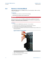
6.2 Remove a Terminal Block................................................................................................................70
6.3 Remove the Address Plug............................................................................................................... 71
6.4 Remove the CHARM Address Terminal Block..................................................................................71
6.5 Remove the +24 V DC Power Module............................................................................................. 71
Chapter 7 Hazardous location installation.................................................................................... 73
7.1 General installation requirements...................................................................................................73
7.2 Connection requirements...............................................................................................................73
7.3 Special conditions of safe use......................................................................................................... 73
7.4 Technical data, explosion protection.............................................................................................. 74
7.5 Revision history.............................................................................................................................. 75
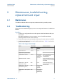
Chapter 8 Maintenance, troubleshooting, replacement and repair .............................................. 77
8.1 Maintenance.................................................................................................................................. 77
8.2 Troubleshooting.............................................................................................................................77
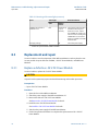
8.3 Replacement and repair................................................................................................................. 78
8.3.1 Replace a defective +24 V DC Power Module............................................................................... 78
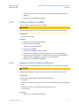
8.3.2 Replace a defective CHARM.........................................................................................................79
8.3.3 Replace a defective AMS Asset Monitor....................................................................................... 79
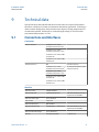
Chapter 9 Technical data..............................................................................................................81
9.1 Connections and interfaces............................................................................................................ 81
9.2 Indications and buttons..................................................................................................................82
Contents Installation Guide
April 2020 MHM-97923-PBF
vi MHM-97923-PBF, Rev. 1.0

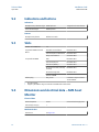
9.3 Slots............................................................................................................................................... 82
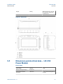
9.4 Dimensions and electrical data – AMS Asset Monitor......................................................................82
9.5 Dimensions and electrical data – +24 V DC Power Module..............................................................83
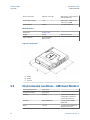
9.6 Environmental conditions – AMS Asset Monitor............................................................................. 84
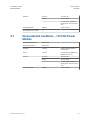
9.7 Environmental conditions – +24 V DC Power Module..................................................................... 85
Chapter 10 Certificates.................................................................................................................. 87
Installation Guide Contents
MHM-97923-PBF April 2020
MHM-97923-PBF, Rev. 1.0 vii

Contents Installation Guide
April 2020 MHM-97923-PBF
viii MHM-97923-PBF, Rev. 1.0

1 General
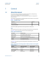
1.1 About this manual
This manual contains specifications, wiring diagrams, dimensions, and step-by-step
instructions for installing the AMS Asset Monitor hardware.
Read this guide completely prior to starting installation of the device. Comply with all
safety instructions.
This installation guides applies for an AMS Asset Monitor with a hardware revision listed in
Table 1-1. See type plate for revision level.
Table 1-1: Hardware revision
Component Revision
AMS Asset Monitor 15
+24 V DC Power Module 08
Include the installation guide when transferring the device to third parties.
Note
When requesting technical support, indicate type and serial number from the type plate.
See Table 1-2 for a list of documents referred to in this installation guide.
Table 1-2: Referenced documents
Part number Document name
MHM-97924-PBF Operating Manual AMS Asset Monitor
MHM-97925-PBF Installation Guide VI Piezo CHARM
D800040X072 DeltaV
™
S-series and CHARMs Hardware Reference
12P5401 Div. 2 Installation Instruction
12P5403 Zone 2 Installation Instruction
See Table 1-3 for product type and ordering numbers of the hardware referred to in this
installation guide.
Table 1-3: Product type and ordering numbers of AMS Asset Monitor and compatible
DeltaV hardware
Hardware Product type number Ordering number
AMS Asset Monitor AM 5820-IM SE8701T01-IM
+24 V DC Power Module AM 5730 SE8701T02-IP
VI Piezo CHARM AM 5125 SE8701V01-PZ
RTD CHARM KL3031X1-BA1 SE4303T03-RS
Installation Guide General
MHM-97923-PBF April 2020
MHM-97923-PBF, Rev. 1.0 9

Table 1-3: Product type and ordering numbers of AMS Asset Monitor and compatible
DeltaV hardware
(continued)
Hardware Product type number Ordering number
Thermocouple/mV input
CHARM
KL3032X1-BA1 SE4303T02-RS
AI 4 to 20 mA CHARM KL3021X1-BA1 SE4303T01-RS
DI 24 V DC Low-Side Sens (dry
contact) CHARM
KL3003X1-BA1 SE4301T02-RS
DO 24 V DC High-Side CHARM KL3002X1-BA1 SE4302T01-RS
Standard Terminal Block KL4502X1-BA1 SE4501-RS
Thermocouple/mV Terminal
Block
KL4502X1-NA1 SE4504-RS
Relay Output Terminal Block KL4502X1-MA1 SE4503-RS
Address Terminal Screw Block KL4502X1-DA1 KL4502X1-DA1-RS
Address Terminal Plug #1 KL4501X1-BA1 KL4501X1-BA1-RS
CHARM labeling component KL4502X1-VA1 KL4502X1-VA1-RS
Replacement label for labeling
component
--- SE4606T02-RS
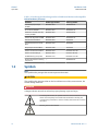
1.2 Symbols
Note
This symbol marks passages that contain important information.
CAUTION
This symbol marks operations that can lead to malfunctions or faulty measurements, but
will not damage the device.
DANGER
A danger indicates actions that can lead to property damage or personal injury.
According to IEC 61010, this symbol means that the documentation of the
device must completely be read and understood before installing and
commissioning of the device. Observe all safety related instructions in this
document.
Warning, electric shock hazard.
General Installation Guide
April 2020 MHM-97923-PBF
10 MHM-97923-PBF, Rev. 1.0

According to IEC 61010, this symbol means that this device must be
operated with DC voltage.
1.3 Liability and guarantee
Emerson is not liable for damages that occur due to improper use. Proper use also includes
the knowledge of, and compliance with, this document.
Customer changes to the device that have not been approved expressly by Emerson will
result in the loss of guarantee.
Due to continuous research and further development, Emerson reserves the right to
change technical specifications without notice.
1.4 Incoming goods inspection
Check the content of the shipment to ensure that it is complete. Visibly inspect the goods
to determine if the device has been damaged during transport. The following parts are at
least included in the scope of delivery and must be contained in the shipment:
• AMS Asset Monitor
• Quick Start Guide AMS Asset Monitor (MHM-97926-PBF)
If the contents are incomplete, or if you observe any defects, file a complaint with the
carrier immediately. Inform the responsible Emerson sales organization, so your device
can be replaced. In this case, attach a tag with customer name and the observed defect.
Additional parts are required to set up an operable system, see About the AMS Asset
Monitor hardware for details.
1.5 Technical support
You may need to ship this product for return, replacement, or repair to an Emerson
Product Service Center. Before shipping this product, contact Emerson Product Support to
obtain a Return Materials Authorization (RMA) number and receive additional instructions.
Product Support
Emerson provides a variety of ways to reach your Product Support team to get the answers
you need when you need them:
Phone
Toll free 800.833.8314 (U.S. and Canada)
+1.512.832.3774 (Latin America)
+63.2702.1111 (Asia Pacific, Europe, and Middle East)
Email
Web
http://www.emerson.com/en-us/contact-us
To search for documentation, visit http://www.emerson.com.
To view toll free numbers for specific countries, visit http://www.emersonprocess.com/
technicalsupport.
Installation Guide
General
MHM-97923-PBF April 2020
MHM-97923-PBF, Rev. 1.0 11

Note
If the equipment has been exposed to a hazardous substance, a Material Safety Data Sheet
(MSDS) must be included with the returned materials. An MSDS is required by law to be
available to people exposed to specific hazardous substances.
1.6 Storage and transport
Store and transport the device only in its original packaging. Technical data specifies the
environmental conditions for storage and support.
1.7 Disposal of the device
Provided that no repurchase or disposal agreement exists, recycle the following
components at appropriate facilities:
• Recyclable metal
• Plastic elements
Sort the remaining components for disposal, based on their condition. National laws or
provisions on waste disposal and protection of the environment apply.
Note
Environmental hazards! Electrical waste and electronic components are subject to
treatment as special waste and may only be disposed by approved specialized companies.
1.8 China RoHS Compliance
Our products manufactured later than June 30, 2016 and those which are sold in the
People's Republic of China are marked with one of the following two logos to indicate the
Environmental Friendly Use Period in which it can be used safely under normal operating
conditions.
Products without below mentioned marking are either manufactured before June 30 or
are non-electrical equipment products (EEP).
Circling arrow symbol with "e": The product contains no hazardous substances over
the Maximum Concentration Value and it has an indefinite Environmental Friendly
Use Period.
Circling arrow symbol with a number: This product contains certain hazardous
substances over the Maximum Concentration Value and it can be used safely under
normal operating conditions for the number of years indicated in the symbol. The
names and contents of hazardous substances can be found in the folder "China
RoHS Compliance Certificates" on the documentation CD or DVD enclosed with the
product.
General Installation Guide
April 2020 MHM-97923-PBF
12 MHM-97923-PBF, Rev. 1.0

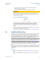
1.9 Installation awareness
Note
When planning a measurement, observe the following items:
• Consider environmental conditions which might have an influence on the
measurement such as temperature, humidity, substances aggressive to the sensor,
and pollution.
• Always use a stiff and vibration-free sensor holder.
• Define a suitable measuring range, not larger than necessary, in consultation with the
operator of the plant.
• Define the trip limit in consultation with the operator of the plant.
• Take measurement deviations into account when defining the trip limit.
• Use a sensor that meets the requirements of the defined measuring range.
• Ensure an EMC-compatible installation including the use of proper cables.
• Ensure proper function of the measurement before activating the measurement for
regular operation.
Installation Guide General
MHM-97923-PBF April 2020
MHM-97923-PBF, Rev. 1.0 13

General Installation Guide
April 2020 MHM-97923-PBF
14 MHM-97923-PBF, Rev. 1.0

2 Safety instructions
To ensure safe operation, carefully observe all instructions in this manual.
The correct and safe use of this device requires that operating and service personnel both
understand and comply with general safety guidelines and observe the special safety
comments listed in this manual. Where necessary, safety-sensitive points on the device
are marked.
DANGER
Because the device is electrical equipment, commissioning and service must be performed
only by trained and authorized personnel. Maintenance must be carried out only by
trained, specialized, and experienced personnel.
2.1 Using the device
Install and use the device as specified in this document.
If the device is used in a manner not specified by the manufacturer, the functions and
protection provided by the device may be impaired.
2.2 Owner's responsibility
If there is a reason to suspect that hazard-free operation, and thus, adequate machine
protection is no longer possible, take the device out of operation and safeguard it from
unintentional operation. This is the case:
• if the device shows visible damage.
• if the device no longer works.
• after any kind of overload that has exceeded the permissible limits (such as those
detailed in chapter "Technical data," section "Environmental conditions").
DANGER
If device tests have to be completed during operation or if the device has to be replaced or
decommissioned, it will impair the machine protection and may cause the machine to
shut down. Make sure to deactivate machine protection before starting such work, and
reactivate it after work has been completed.
2.3 Radio interference
The device is carefully shielded and tested to be technically immune to radio interference
and complies with current standards. However, if you operate this device together with
other peripheral devices that are not properly shielded against radio interference,
disturbances and radio interferences may occur.
Installation Guide Safety instructions
MHM-97923-PBF April 2020
MHM-97923-PBF, Rev. 1.0 15

2.4 ESD safety
DANGER
Internal components can be damaged or destroyed due to electrostatic discharge (ESD)
during the handling of the device.
Take suitable precautions before handling the device to prevent electrostatic discharges
through the sensor electronics. Such measures might include, for example, wearing an
ESD bracelet. Transport and storage of electronic components may only be made in ESD-
safe packaging.
Handle the device with particular care during dry meteorological conditions with relative
humidity below 30% as electrostatic discharges can appear more frequently.
2.5 Important information about hazardous live
voltages
DANGER
The KL4502X1-MA1 CHARM Relay Output Terminal Block may have hazardous live
voltages on its output terminals. This terminal block is capable to switch field power of 250
V AC. Ensure that proper safety precautions, such as de-energizing field power, are
observed during installation, maintenance, or any time wiring changes are made to the
CHARM Relay Output Terminal Block.
For further information about hazardous live voltages see Wiring guidelines and CSA –
General safety.
Safety instructions Installation Guide
April 2020 MHM-97923-PBF
16 MHM-97923-PBF, Rev. 1.0

3 Planning the installation
Emerson recommends two people to mount the AMS Asset Monitor.
3.1 Tools required to install the hardware
Standard tools are required to install the AMS Asset Monitor hardware:
Wire cutter
For shortening the connection wires.
Wire stripper
For removing the insulation from the wire.
Crimper
For crimping ferrules.
3.5 mm flat-tip
screwdriver
For the CHARM Terminal Block, power supply terminals, and
baseplate grounding terminals.
PH 2 cross-tip
screwdriver
For the internal grounding terminals of the AMS Asset
Monitor.
PZ 3 cross-tip
screwdriver
For the door screws and grounding terminal at the AMS Asset
Monitor bottom.
Screwdriver
Suitable for the screws, selected for mounting the AMS Asset
Monitor on a wall, mounting plate, or mounting frame. Size
and type of the screwdriver depends on the selected fixing
method.
Voltmeter
To check the supply voltage and the connected signals.
3.2 Torque limits for mounting screws
Table 3-1 lists the permissible maximum torque limits for the screws of the AMS Asset
Monitor hardware.
Table 3-1: Maximum torque limits
Hardware part Maximum torque limit
Power supply terminal screws 0.5 Nm
CHARM Terminal Block screws 0.45 Nm
Cable shield grounding terminals 0.45 Nm
Grounding terminal at the bottom 8.7 Nm
Additional grounding terminals for ground connection 5.1 Nm
The recommended tightening torque is the maximum torque limit minus 20%.
Installation Guide Planning the installation
MHM-97923-PBF April 2020
MHM-97923-PBF, Rev. 1.0 17

3.3 Wiring guidelines
This section contains general information and wiring hints. As always, proper cable
installation depends on observation and judgment based on the situation on-site. Observe
the following points for a reliable cable installation:
• Install cables according to general standards for measuring and control cables.
• Separate AC voltage circuits from low voltage signals to comply with safety
recommendations and to mitigate induced noise in the signals. This good practice is
recommended by Emerson although any signal type can be installed in any CHARM slot
of the AMS Asset Monitor.
• If possible, install cables in metallic cable channels or tubes.
• Observe an orthogonal cable routing.
• Do not squeeze, bent, or twist cables. Always observe the permissible bending radius
of the used cable.
• Install cables strain-free and spin-free to protect them against mechanical damages.
• Affix cables to a secure surface at regular, short distances.
• Ensure that no parts of the cable touch any rotating parts of the machine.
• Note that machine parts or other metallic parts can expand or shrink due to
temperature influences. Always install cables with a cable length reserve to
compensate the thermal behavior of such parts.
•
Always use ferrules for stranded wires. Ensure that all strands are covered by the
ferrule so that no strand can contact an adjacent terminal. When strands are
stripped 10 mm and ferrules are not used, consider that there is a risk of short
circuit – a possibility of accidental contact between HAZARDOUS LIVE parts of
different polarity.
• At environmental temperatures of 50°C and above use cables suitable for temperatures
above 60°C within the AMS Asset Monitor.
See Table 3-2 for the permissible wire-cross sections for the voltage supply terminals and
cable shield terminals. For the maximum tightening torque see Torque limits for mounting
screws.
Table 3-2: Permissible wire-cross sections
Wire description Wire cross-section
Minimum Maximum
Power supply terminals Conductor cross section
stranded
0.2 mm
2
2.5 mm
2
Conductor cross section
stranded AWG
24 12
Cable shield terminals Conductor cross section 0.32 mm
2
2.5 mm
2
Conductor cross section
AWG
22 14
Planning the installation Installation Guide
April 2020 MHM-97923-PBF
18 MHM-97923-PBF, Rev. 1.0

Table 3-2: Permissible wire-cross sections
(continued)
Wire description Wire cross-section
Minimum Maximum
CHARM Terminal Blocks Conductor cross section
AWG (stranded or solid)
22 14
The recommended stripping length of the wires is 10 mm.
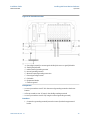
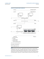
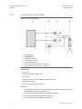
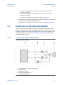
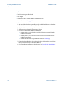
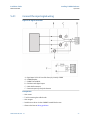
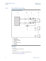
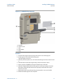
3.3.1 Wiring overview
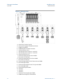
See Figure 3-1 for an example overview of a standard wiring of an AMS Asset Monitor.
Installation Guide Planning the installation
MHM-97923-PBF April 2020
MHM-97923-PBF, Rev. 1.0 19

Figure 3-1: Wiring overview
A. Connection to protective ground
B. 24 V DC power supply for the AMS Asset Monitor
C. CHARM Terminal Block
D. CHARM Baseplate with shield connection
E. 2-wire piezoelectric sensor
F. Top view of the sensor connector – terminal A
G. Top view of the sensor connector – terminal B
H. Connection SE8701V01-PZ
I. Connection analog input AI 4-20 mA CHARM
J. Device with 4-20 mA output
K. Connection analog output AO 4-20 mA CHARM
L. Device with 4-20 mA input
M. Connection digital input DI 24 V DC low-side sense CHARM
N. Device with digital output
O. Connection digital output DO 24 V DC high-side CHARM
P. Device with digital input
Q. Connection RTD Input CHARM
R. 4-wire RTD
S. 3-wire RTD
T. 2-wire RTD
U. Connection Thermocouple Input CHARM
V. CHARM Thermocouple/mV Terminal Block
Planning the installation Installation Guide
April 2020 MHM-97923-PBF
20 MHM-97923-PBF, Rev. 1.0
La pagina si sta caricando...
La pagina si sta caricando...
La pagina si sta caricando...
La pagina si sta caricando...
La pagina si sta caricando...
La pagina si sta caricando...
La pagina si sta caricando...
La pagina si sta caricando...
La pagina si sta caricando...
La pagina si sta caricando...
La pagina si sta caricando...
La pagina si sta caricando...
La pagina si sta caricando...
La pagina si sta caricando...
La pagina si sta caricando...
La pagina si sta caricando...
La pagina si sta caricando...
La pagina si sta caricando...
La pagina si sta caricando...
La pagina si sta caricando...
La pagina si sta caricando...
La pagina si sta caricando...
La pagina si sta caricando...
La pagina si sta caricando...
La pagina si sta caricando...
La pagina si sta caricando...
La pagina si sta caricando...
La pagina si sta caricando...
La pagina si sta caricando...
La pagina si sta caricando...
La pagina si sta caricando...
La pagina si sta caricando...
La pagina si sta caricando...
La pagina si sta caricando...
La pagina si sta caricando...
La pagina si sta caricando...
La pagina si sta caricando...
La pagina si sta caricando...
La pagina si sta caricando...
La pagina si sta caricando...
La pagina si sta caricando...
La pagina si sta caricando...
La pagina si sta caricando...
La pagina si sta caricando...
La pagina si sta caricando...
La pagina si sta caricando...
La pagina si sta caricando...
La pagina si sta caricando...
La pagina si sta caricando...
La pagina si sta caricando...
La pagina si sta caricando...
La pagina si sta caricando...
La pagina si sta caricando...
La pagina si sta caricando...
La pagina si sta caricando...
La pagina si sta caricando...
La pagina si sta caricando...
La pagina si sta caricando...
La pagina si sta caricando...
La pagina si sta caricando...
La pagina si sta caricando...
La pagina si sta caricando...
La pagina si sta caricando...
La pagina si sta caricando...
La pagina si sta caricando...
La pagina si sta caricando...
La pagina si sta caricando...
La pagina si sta caricando...
La pagina si sta caricando...
La pagina si sta caricando...
La pagina si sta caricando...
La pagina si sta caricando...
-
 1
1
-
 2
2
-
 3
3
-
 4
4
-
 5
5
-
 6
6
-
 7
7
-
 8
8
-
 9
9
-
 10
10
-
 11
11
-
 12
12
-
 13
13
-
 14
14
-
 15
15
-
 16
16
-
 17
17
-
 18
18
-
 19
19
-
 20
20
-
 21
21
-
 22
22
-
 23
23
-
 24
24
-
 25
25
-
 26
26
-
 27
27
-
 28
28
-
 29
29
-
 30
30
-
 31
31
-
 32
32
-
 33
33
-
 34
34
-
 35
35
-
 36
36
-
 37
37
-
 38
38
-
 39
39
-
 40
40
-
 41
41
-
 42
42
-
 43
43
-
 44
44
-
 45
45
-
 46
46
-
 47
47
-
 48
48
-
 49
49
-
 50
50
-
 51
51
-
 52
52
-
 53
53
-
 54
54
-
 55
55
-
 56
56
-
 57
57
-
 58
58
-
 59
59
-
 60
60
-
 61
61
-
 62
62
-
 63
63
-
 64
64
-
 65
65
-
 66
66
-
 67
67
-
 68
68
-
 69
69
-
 70
70
-
 71
71
-
 72
72
-
 73
73
-
 74
74
-
 75
75
-
 76
76
-
 77
77
-
 78
78
-
 79
79
-
 80
80
-
 81
81
-
 82
82
-
 83
83
-
 84
84
-
 85
85
-
 86
86
-
 87
87
-
 88
88
-
 89
89
-
 90
90
-
 91
91
-
 92
92


in altre lingue
- English: AMS Asset Monitor Installation guide
Altri documenti
-
 StarTech.com ARMBARDUOV Manuale del proprietario
-
 Hach ORBISPHERE 3662EX Basic User Manual
-
Emerson FB1100 Istruzioni per l'uso
-
Emerson D301801X012 Istruzioni per l'uso
-
Omron S8V-CP Manuale utente
-
Phoenix Contact 3209594 Manuale utente
-
Phoenix Contact 3209565 Istruzioni per l'uso
-
Rosemount Oxymitter 4000 O2 Transmitter-Rev 4.3 Manuale del proprietario
-
Terex Genie GTH-1544 Manuale utente
-
 Kistler 9001C Manuale del proprietario


