Terex Genie GTH-1544 Manuale utente
- Categoria
- Veicolo d'utilità
- Tipo
- Manuale utente

Operator’s Manual
Original Instructions
First Edition
Third Printing
April 2019
Part No. 57.0009.0733
Serial number range
GTH-1544 (Deutz Tier 4 Final)
From GTH15M-601

Contents
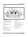
Introduction .......................................................... 1
Symbol and Hazard Pictorials Definitions............ 5
General Safety..................................................... 6
Work Area Safety ................................................. 8
Legend............................................................... 16
Controls ............................................................. 17
Inspections ........................................................ 22
Operating Instructions ....................................... 32
Transport and Lifting Instructions ...................... 44
Maintenance ...................................................... 47
Attachments....................................................... 51
Specifications .................................................... 62
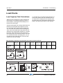
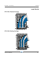
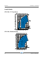
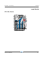
Load Charts ....................................................... 64
Copyright © 2019 by Terex Corporation
First Edition: Third Printing, April 2019
Genie is a registered trademark of Terex
South Dakota, Inc. in the U.S.A. and many
other countries. “GTH” is a trademark of Terex
SouthDakota, Inc.
Complies with ANSI/ITSDF B56.6, CSA B335
April 2019
GTH-1544 Part No. 57.0009.0733
First Edition - Third Printing

April 2019First Edition - Third Printing
Part No. 57.0009.0733 GTH-1544 1
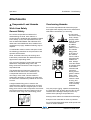
Introduction
About This Manual
Genie appreciates your choice of our machine for
your application. Our number one priority is user
safety, which is best achieved by our joint efforts.
This book is an operation and daily maintenance
manual for the user or operator of a Genie machine.
This manual,along with the AEM Rough Terrain Forklift
Safety Manual and the CCTV operator's manual (if
equipped), should be considered a permanent part of
your machine and should remain with the machine at
all times. If you have any questions, contact Genie.
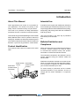
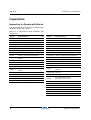
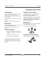
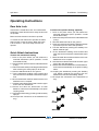
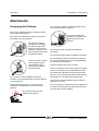
Product Identification
The machine serial number is located on the serial
label.
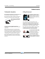
Intended Use
A variable reach rough terrain forklift truck is defined
as a wheeled type truck with a pivoting boom, which
may be equipped with various attachments for picking,
transporting and placing loads with the established
load range charts.
Use of this product in any other way is prohibited
and contrary to its intended
use.
Bulletin Distribution and
Compliance
Safety of product users is of paramount importance
to Genie. Various bulletins are used by Genie
to communicate important safety and product
information to dealers and machine owners.
The information contained in the bulletins is tied to
specific machines using the machine model and
serial number.
Distribution of bulletins is based on the most current
owner on record along with their associated dealer,
so it is important to register your machine and keep
your contact information up to date.
To ensure safety of personnel and the reliable
continued operation of your machine, be sure to
comply with the action indicated in a respective
bulletin.
Serial number
stamp
Serial label
(located inside
chassis)
Serial label
(located inside
fork frame)

April 2019
2 GTH-1544 Part No. 57.0009.0733
First Edition - Third Printing
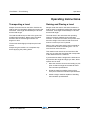
Contacting the Manufacturer
At times it may be necessary to contact Genie.
When you do, be ready to supply the model number
and serial number of your machine, along with your
name and contact information. At minimum, Genie
should be contacted for:
• Accident reporting
• Questions regarding product applications
and safety
• Standards and regulatory compliance
information
• Questions regarding Product Modifications
• Current owner updates, such as changes
in machine ownership or changes in
your contact information. See Transfer of
Ownership, below.
Transfer of Machine Ownership
Taking a few minutes to update owner information
will ensure that you receive important safety,
maintenance and operating information that applies
to your machine.
Please register your machine by visiting us on the
web at www.genielift.com or by calling us toll free
at 1-800-536-1800.
Introduction

April 2019First Edition - Third Printing
Part No. 57.0009.0733 GTH-1544 3
Introduction
Danger
Failure to obey the instructions and
safety rules in this manual will result
in death or serious injury.
Do Not Operate Unless:
R You learn and practice the principles of safe
machine operation contained in this operator’s
manual.
1. Avoid hazardous situations.
Know and understand the safety rules
before going on to the next section.
2. Always perform a pre-operation inspection.
3. Always perform function tests prior to use.
4. Inspect the workplace.
5. Only use the machine as it was intended.
R You read, understand and obey the manufacturer’s
instructions and the safety rules, the safety and
operator’s manuals, and the decals applied on
the machine.
R You read, understand and obey the employer’s
safety rules and worksite regulations.
R You read, understand and obey all applicable
governmental regulations.
R You are properly trained to safely operate the
machine.

April 2019
4 GTH-1544 Part No. 57.0009.0733
First Edition - Third Printing
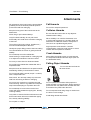
Hazard Classification
Safety alert symbol - used to
alert you to potential personal
injury hazards. Obey all safety
messages that follow this
symbol to avoid possible injury
or death
DANGER
Indicates a hazardous situation
which, if not avoided, will result
in death or serious injury.
WARNING
Indicates a hazardous situation
which, if not avoided, could result
in death or serious injury.
CAUTION
Indicates a hazardous situation
which, if not avoided, could result
in minor or moderate injury.
NOTICE
Indicates a property damage
message.
Introduction
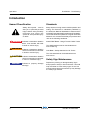
Standards
Many aspects of rough terrain forklift operation and
testing are discussed in standards published by
the American National Standards Institute and the
Industrial Truck Standards Development Foundation.
These standards are updated on a regular basis with
addenda. It is recommended that you purchase and
refer to the following standards.
ANSI/ITSDF B56.6 - Rough Terrain Forklift Trucks
The ANSI standard can be downloaded from
www.ITSDF.org
CSA B335 - Safety Standard for Lift Trucks
The CSA standard can be downloaded from
www.csa.ca
Safety Sign Maintenance
Replace any missing or damaged safety signs.
Keep operator safety in mind at all times. Use mild
soap and water to clean safety signs. Do not use
solvent-based cleaners because they may damage
the safety sign material.

April 2019First Edition - Third Printing
Part No. 57.0009.0733 GTH-1544 5
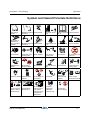
Symbol and Hazard Pictorials Definitions
Maintain required
clearance
Read the operator's
manual
Burn HazardExplosion/burn
hazard
No smoking
No open flame
Allow surfaces to
cool
Crush Hazard Keep clear of
moving parts
Access by
trained and
authorized
personnel only
Electrocution
hazard
Refer to load
charts and manual
Tip-over hazardAlways wear seat
belt
Keep load low
during travel
Crush hazard
Crush hazard
Only use an
approved work
platform
Crush hazard Keep away from
moving parts
Burn hazard Do not loosen cap
until cool
Keep away from
moving parts
Explosion hazard
o
2
N
2
Use nitrogen.
Not use oxygen
No people under
load
Injection hazard
Use a piece of
cardboard or
paper to search
for leaks
Maintain required
clearance
Crush hazard
Tip-over hazard
Explosion/burn
hazard
Fall hazard
Do not level the
machine with an
elevated boom
No smoking. No
open flame
Do not operate
machine unless
area around
machine is clear
of people and
obstructions

April 2019
6 GTH-1544 Part No. 57.0009.0733
First Edition - Third Printing
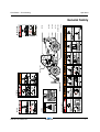
General Safety
237605
DANGER
237601
WARNING
97667
WARNING
237598
WARNING
237970
82558
82558 B
Injection Hazard
Escaping fluid under pressure can
penetrate skin, causing serious injury.
Relieve pressure before disconnecting
hydraulic lines. Keep away from leaks
and pin holes. Use a piece of cardboard
or paper to search for leaks. Do not use
hand.
Fluid injected into skin must be
surgically removed within a few hours
by a doctor familiar with this type of
injury or gangrene will result.
WARNING
97667
215268
237601
214418
1263543
97667
214418
82558
237598
237970
237605
WARNING
WARNING
215268
1263543
Improper operation or maintenance of
this equipment can result in death or
serious injury.
Access by trained and
authorized personnel only.
1263543
A

April 2019First Edition - Third Printing
Part No. 57.0009.0733 GTH-1544 7
General Safety
09.4618.1622
214418
237598
237970
237971
09.4618.1635
09.4618.1622
o
DANGER
2
N
2
09.4618.1635
28236
DANGER
237971
WARNING
DANGER
214418
28236

April 2019
8 GTH-1544 Part No. 57.0009.0733
First Edition - Third Printing
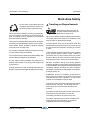
Work Area Safety
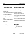
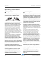
Tip-over Hazards
Using the appropriate load chart for
the machine configuration, confirm
that the load is within the rated
capacity of the machine.
Do not exceed the rated load.
The load center of the fork (if equipped) must be
equal to or less than the load center indicated on
the load chart. If the load center is further from the
fork face than shown on the load chart, refer to the
Load Chart section on this manual.
All loads shown on the load chart are based on
the machine being on firm level ground, the frame
being level, the forks being positioned evenly on the
carriage, the load being centered on the forks, the
tires being properly sized and properly inflated, and
the telehandler being in good operating condition.
If using accessories, read, understand and obey the
decals, instructions and manuals with the accessory.
Do not raise the load unless the ground can support
all forces imposed by the machine.
Do not lower a load without retracting the boom first.
Do not use attachments wich are not approved by
Genie.
Do not operate the machine if the load chart is missing.
Do not exceed the rated capacity for each
configuration.
Do not attemp to jump free of the machine during a
tip-over. The ROPS (Roll Over Protective Structure)
is designed to protect you.
If the telehandler starts to
tip over:
- do not jump
- Brace yourself and stay
in the seat
- Keep your seatbelt
fastened
- Hold on firmly
- Lean away from the point
of impact
- Keep head, arms, hands,
legs and all other body
parts inside the operator's
cab at all times.
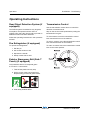
Do not raise the boom unless the
machine is level. The machine level
indicator should be at zero degrees.
Do not level the machine using the frame sway
control unless the boom angle indicator is at zero
degrees or less.
Do not use the sway control to position
an elevated load.
Do not raise a load and then drive to position it.
When driving, keep the boom at
or below horizontal and keep the
load close to the ground.
Operate the machine at speeds that will keep the
load under control. Start and stop movements
smoothly.

April 2019First Edition - Third Printing
Part No. 57.0009.0733 GTH-1544 9
Do not raise a load unless the load
is properly positioned or secured on
the forks or approved attachment.
Do not operate the machine in strong or gusty winds.
Do not increase the surface area of the carriage or
load. Increasing the area exposed to the wind will
decrease machine stability.
Use extreme care and slow speeds while driving the
machine in the travel position across uneven terrain,
steep grades, debris, unstable or slippery surfaces
and near holes and drop-offs.
Do not alter or disable machine components that in
any way affect safety and stability.
Do not replace items critical to machine stability with
items of different weight or specification.
Do not replace factory-installed tires with tires of
different specification or ply rating, unless approved
by the factory.
If using accessories, read, understand and obey the
decals, instructions and manuals with the accessory.
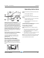
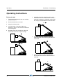
Traveling on Slopes Hazards
When driving, keep the boom at
or below horizontal and keep the
load close to the ground.
When the machine is loaded, always travel with the
load uphill. When the machine is unloaded, travel
with the forks or attachment downhill.
On steep terrain, drive only up and down a hill, and
always keep the machine in gear. Do not turn across
the slope when the machine is traveling up or down
a slope.
Limit travel path and speed according to the condition
of the ground surface, traction, slope, location of
personnel and any other factors which may create
a hazard. Never drive the machine unless the mast
and equipment are in their proper travel position.
Whether a machine will tip over during dynamic
machine operation involves many factors that need
to be considered. Among these are pavement/ground
conditions, stability and slope, as well as machine
equipment, operator skill, load position, tire inflation,
machine speed, etc.
Additionally, tip-over of a machine is dependent in
large part upon operator inputs such as the speed
and smoothness of the operation, as well as the
position of the attachment and its load.
Construction sites and roads will frequently change
slope from place to place, can be hard and soft,
and change due to construction activities and
weather.
Operators should be properly trained and use their
best judgment and experience to take the
necessary precautions to prevent a tip-over.
Operators must assess the job site variables and
avoid exceeding the machine's (or operator's)
capabilities for terrain and conditions.
Work Area Safety

April 2019
10 GTH-1544 Part No. 57.0009.0733
First Edition - Third Printing
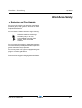
Fall Hazards
Always wear a seat belt when
operating the machine.
Always remain completely inside the cab when
operating the machine.
When getting in and out of the cab, face the machine,
use the steps and handrails provided and always
maintain three-point contact.
Do not use the steering wheel or any other controls
as handrails.
Do not allow riders on the machine
or forks.
Do not lift personnel with this
machine unless it is equipped with
an approved work platform. See
Work Platform section.
Collision Hazards
Keep people, equipment and
material out of the work area.
Do not operate the machine
while people are under or near
an elevated boom, whether it is
loaded or unloaded.
Do not put the transmission into gear unless the
brake is applied and personnel and bystanders are
clear of the machine and load.
Do not drive the machine if visibility is obstructed.
Use a signal person when visibility is obstructed, and
keep the signal person in view at all times.
Use prearranged hand signals to communicate.
Do not raise the boom unless the brake is applied.
Do not operate, without fenders, in conditions where
loose debris could hit the operator or accumulate on
the cab windows.
Do not operate the machine with a faulty back-up
alarm. The back-up alarm should sound when the
machine is in reverse.
Do not operate the machine in low light conditions.
An optional work and road light package is available.
Operators must comply with employer, job site
and governmental rules regarding use of personal
protective equipment.
Do not drive the machine directly up to anyone.
Always make sure that mirrors and cab glass are
clean and do not obstruct the operators view of the
travel path or load.
Scan the area prior to operating the machine. Look
in the direction of travel. Use mirrors to assist in
checking all around the machine.
Keep windows and mirrors clean, adjusted and in
good repair.
Be aware of the machine load swing area.
Do not rely on the rear proximity alarm system
to determine if personnel or objects are behind
the machine. The system has limitations due to
maintenance practices, the size or shape of the
object, composition, environmental conditions and
operating range. This system is set up for detection
at a reverse speed of a maximum of 3 feet per second
/ 0.9 meters per second (walking pace). Refer to the
detection zone chart in the back of this manual.
Work Area Safety

April 2019First Edition - Third Printing
Part No. 57.0009.0733 GTH-1544 11
Work Area Safety
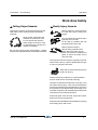
Falling Object Hazards
Operate the machine at speeds that will keep the
load under control. Start and stop movements
smoothly.
Keep people, equipment and
material out of the work area.
Do not operate the machine
while people are under or near
an elevated boom, whether it is
loaded or unloaded.
Be sure the load is secure before lifting it. Always
make sure the quick attach pin is inserted and secured.
Bodily Injury Hazards
Always adjust the seat and fasten
the seat belt before starting the
engine.
Do not operate the machine with a
hydraulic oil or air leak.
An air leak or hydraulic leak can
penetrate and/or burn skin.
Relieve pressure before
disconnecting hydraulic lines.
Keep away from leaks and pin
holes. Use a piece of cardboard or
paper to search for leaks. Do not
use your hand.
Fluid injected into skin must be surgically removed
within a few hours by a doctor familiar with this type
of injury or gangrene will result.
Stay clear of belts and fans when the
engine is running.
Always operate the machine in a well-ventilated
area to avoid carbon monoxide poisoning.
Improper contact with components under any cover
will cause serious injury. Only trained maintenance
personnel should access compartments. Access by
the operator is only advised when performing a pre-
operation inspection. All compartments must remain
closed and secured during operation.
Keep body parts, such as hand, fingers annd arms,
away from moving components.
Always use provided latches and handles for opening
and closing doors and covers.

April 2019
12 GTH-1544 Part No. 57.0009.0733
First Edition - Third Printing
Damaged Machine Hazards
Do not use a damaged or malfunctioning machine.
Conduct a thorough pre-operation inspection of the
machine and test all functions before each work shift.
Immediately tag and remove from service a damaged
or malfunctioning machine.
Be sure all maintenance has been performed as
specified in this manual and the appropriate Genie
service manual.
Be sure all decals are in place and legible.
Be sure the operator's and safety manuals are
complete, legible and in the storage container located
in the cab.
Do not attempt to start the machine by towing or
pushing.
Do not attempt to use the forks or attachments for
prying wedged or frozen loads free.
Do not push or pull objects or loads with the forks,
attachment or boom.
Do not exceed 20 mph travelling speed when driving
downhill.
If engine display lights or engine condition indicator
lights are on, see the operating Instructions section.
Continued use when engine lights are on could result
in reduced torque and engine speed.
Component Damage Hazards
Do not use any battery or charger greater than 12V
to jump-start the engine.
Do not use the machine as a ground for welding.
Do not operate the machine when the SCR (selective
catalytic reduction) regeneration operation is running.
See Operating Instructions section.
Diesel exhaust fluid (DEF) is corrosive to metal
and paint. If DEF is spilled, it should be cleaned up
immediately with warm water.
Do not use high pressure water on the air filter grid.
Crush Hazards
Keep clear of moving parts during machine operation
and make sure personnel and bystanders are kept
clear of moving parts during operation.
Set the parking brake, put the transmission in neutral
and lower the carriage or the attachment to the ground
before leaving the machine.
Keep clear of elevated components.
Support components before performing service.
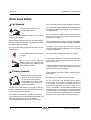
Burn Hazards
Allow hot surfaces to cool before
touching or servicing
Work Area Safety

April 2019First Edition - Third Printing
Part No. 57.0009.0733 GTH-1544 13
Explosion and Fire Hazards
Do not start the engine if you smell or detect liquid
petroleum gas (LPG), gasoline, diesel fuel or other
explosive substances.
Do not refuel the machine with the engine running.
Refuel the machine and charge
the battery only in an open,
well-ventilated area away from
sparks, flames and lighted
tobacco.
Do not operate the machine in hazardous locations
or locations where potentially flammable or explosive
gases or particles may be present.
Do not spray ether into engines equipped with glow
plugs or air intake grid heaters.
Do not use air or oxygen for charging the accumulators.
Work Area Safety

April 2019
14 GTH-1544 Part No. 57.0009.0733
First Edition - Third Printing
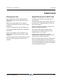
Electrocution Hazards
This machine is not electrically insulated and will
not provide protection from contact with or
proximity to electrical current.
Obey all local and governmental
regulations regarding required
clearance from electrical power
lines. At a minimum, the
required clearance contained in
the chart below must be
followed.
Line Voltage Required Clearance
0 to 50kV 10 ft 3.05 m
>50 to 200kV 15 ft 4.60 m
>200 to 350kV 20 ft 6.10 m
>350 to 500kV 25 ft 7.62 m
>500 to 750kV 35 ft 10.67 m
>750 to 1000kV 45 ft 13.72 m
over 1000kV see below
For power lines over 1000kV, the minimum
clearance distance must be established by the
utility owner or operator or by a registered
professional engineer who is a qualified person
with respect to electrical power transmission and
distribution.
Do not use the machine as a ground for welding.
Always contact the electrical power line owner. The
electrical power shall be disconnected or the power
lines moved or insulated before machine
operations begin.
Allow for boom and attachment movement, electrical
line sway or sag, and beware of strong or gusty winds.
Keep away from the machine if it contacts
energized power lines. Personnel on the ground or
in the platform must not touch or operate the
machine until energized power lines are shut off.
Do not operate the machine during lightning or
storms.
Work Area Safety

April 2019First Edition - Third Printing
Part No. 57.0009.0733 GTH-1544 15
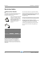
Battery Safety
Burn Hazards
Batteries contain acid.
Always wear protective
clothing and eye wear when
working with batteries.
Avoid spilling or contacting
battery acid. Neutralize
battery acid spills with baking
soda and water.
Explosion Hazards
Keep sparks, flames and
lighted tobacco away from
batteries. Batteries emit
explosive gas.
Electrocution Hazard
Avoid contact with electrical terminal.
During maintenance or repair works, and while
welding, disconnect the battery turning the cut-out
switch (see Inspection for Decals section).
After turning off the engine, wait for 120 seconds
before activate the cut-out switch.
Employer's Responsibilities
Employers are responsible for providing a safe
work environment and for complying with local and
national governmental regulations.
Personal Safety
Be sure that everyone working on or near this machine
is familiar with the applicable safety precautions.
Work Area Safety

April 2019
16 GTH-1544 Part No. 57.0009.0733
First Edition - Third Printing
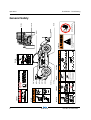
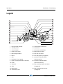
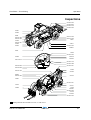
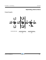
Legend
1. Left/right level indicator
2. Steering wheel
3. Control handle
4. Rear convex mirror
5. Boom angle indicator
6. Boom
7. Cab
8. Hydraulic oil level gauge
9. Engine (on opposite side of machine)
10. Forks
11. Seat belt
12. Seat
13. Brake pedal
14. Accelerator pedal
15. Transmission control lever
16. Load charts
17. Front/rear level indicator
18. Right rear view mirror
19. Left rear view mirror
20. Fire extinguisher (if equipped)
21. Operator’s manual location
(canopy version)
22. Operator’s manual location
(closed cab version)
23. Rear proximity display and alarm
(if equipped)
24. Rear proximity alarm sensor
(if equipped)

April 2019First Edition - Third Printing
Part No. 57.0009.0733 GTH-1544 17
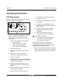
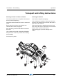
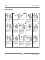
Controls
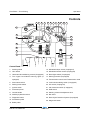
Control Panel
1. Steering wheel
2. Horn button
3. Heater and Air conditioning controls (if equipped)
4. Turn signal lever/Hazard warning lights (if
equipped)
5. Steer select switch
6. Parking brake switch
7. Ignition switch
8. Instrument panel
9. Control handle
10. Auxiliary hydraulics switch
11. Diagnostic button
12. Accelerator pedal
13. Brake pedal
14. Windshield wiper switch (if equipped)
15. Windshield washer switch (if equipped)
16. Road lights switch (if equipped)
17. Work light switch (if equipped)
18. Transmission control lever/Transmission mode
19. Lock/unlock enabling switch (if equipped)
20. A/C switch (if equipped)
21. Cab heater fan switch (if equipped)
22. SCR switch
23. Steering column tilt adjustment lock
24. Not active
25. Rear Object Detection System (if equipped)
26. Diagnostic button
P

April 2019
18 GTH-1544 Part No. 57.0009.0733
First Edition - Third Printing
Controls
1 Steering wheel
Turn the steering wheel to the right to turn the
front wheels to the right. Turn the steering wheel
to the left to turn the front wheels to the left.
2 Horn button
Press this button and the horn will sound. Release
the button and the horn will stop.
3 Heater and air conditioning controls (if equipped)
4 Turn signal lever/Hazard warning lights (if
equipped)
Move the lever forward to activate the left turn
signal. Move the lever backward to activate the
right turn signal.
Rotate the end of the lever backward to activate
the hazard warning lights. Rotate the end of the
lever forward to deactivate the hazard warning
lights.
5 Steering mode selector
Rotate the steer selector to the right side to select
four-wheel steer. Rotate the steer selector to the
middle position to select two-wheel steer. Rotate
the steer selector to the left to select crab steer.
6 Parking brake switch
Push the bottom of the rocker switch to turn the
parking brake on. Push the top of the switch to
turn the parking brake off.
7 Ignition switch
Turn the key until the engine starts; when
released, key springs back to pos. I automatically.
Position P is not active.
8 Instrument panel
9 Control handle
Pull the Control handle back and the boom will
raise. Push the Control handle forward and the
boom will lower. Push the Control handle to the
right and the boom will extend. Pull the Control
handle to the left and the boom will retract. Hold
down the grey thumb switch and pull the Control
handle back and the forks will tilt up. Hold down
the grey thumb switch and push the Control
handle forward and the forks will tilt down. Hold
the grey finger switch and push the Control
handle to the right and the machine will sway
to the right. Hold the grey finger switch and pull
the Control handle to the left and the machine
sway to the left.
10 Auxiliary hydraulics switch
Push the left side of the auxiliary hydraulics button
and the carriage will swing or rotate to the left.
Push the right side of the auxiliary hydraulics
button and the carriage will swing or rotate to
the right.
Push and Hold the Lock/unlock enabling switch 19
and push the left side of the auxiliary hydraulics
button to lock the attachment; Push and Hold
the Lock/unlock enabling switch 19 and push
the right side of the auxiliary hydraulics button
to unlock the attachment.
11 Diagnostic button
Push the button to scroll the LCD screen menu.
12 Accelerator pedal
13 Brake pedal
14 Windshield wiper switch (if equipped)
Push the switch to turn the wiper on: first position
for low speed and second position for high speed.
Push the top of the switch to turn the wiper off.
15 Windshield washer switch (if equipped)
Push and hold the switch to turn the washer on.
Release the switch to turn the washer off.
16 Road lights switch (if equipped)
Push the bottom of the switch to turn the road
lights on. Push the top of the switch to turn it off.
17 Work light switch (if equipped)
Push the bottom of the switch to turn the boom
working light on. Push the top of the switch to
turn it off.
La pagina si sta caricando...
La pagina si sta caricando...
La pagina si sta caricando...
La pagina si sta caricando...
La pagina si sta caricando...
La pagina si sta caricando...
La pagina si sta caricando...
La pagina si sta caricando...
La pagina si sta caricando...
La pagina si sta caricando...
La pagina si sta caricando...
La pagina si sta caricando...
La pagina si sta caricando...
La pagina si sta caricando...
La pagina si sta caricando...
La pagina si sta caricando...
La pagina si sta caricando...
La pagina si sta caricando...
La pagina si sta caricando...
La pagina si sta caricando...
La pagina si sta caricando...
La pagina si sta caricando...
La pagina si sta caricando...
La pagina si sta caricando...
La pagina si sta caricando...
La pagina si sta caricando...
La pagina si sta caricando...
La pagina si sta caricando...
La pagina si sta caricando...
La pagina si sta caricando...
La pagina si sta caricando...
La pagina si sta caricando...
La pagina si sta caricando...
La pagina si sta caricando...
La pagina si sta caricando...
La pagina si sta caricando...
La pagina si sta caricando...
La pagina si sta caricando...
La pagina si sta caricando...
La pagina si sta caricando...
La pagina si sta caricando...
La pagina si sta caricando...
La pagina si sta caricando...
La pagina si sta caricando...
La pagina si sta caricando...
La pagina si sta caricando...
La pagina si sta caricando...
La pagina si sta caricando...
La pagina si sta caricando...
La pagina si sta caricando...
-
 1
1
-
 2
2
-
 3
3
-
 4
4
-
 5
5
-
 6
6
-
 7
7
-
 8
8
-
 9
9
-
 10
10
-
 11
11
-
 12
12
-
 13
13
-
 14
14
-
 15
15
-
 16
16
-
 17
17
-
 18
18
-
 19
19
-
 20
20
-
 21
21
-
 22
22
-
 23
23
-
 24
24
-
 25
25
-
 26
26
-
 27
27
-
 28
28
-
 29
29
-
 30
30
-
 31
31
-
 32
32
-
 33
33
-
 34
34
-
 35
35
-
 36
36
-
 37
37
-
 38
38
-
 39
39
-
 40
40
-
 41
41
-
 42
42
-
 43
43
-
 44
44
-
 45
45
-
 46
46
-
 47
47
-
 48
48
-
 49
49
-
 50
50
-
 51
51
-
 52
52
-
 53
53
-
 54
54
-
 55
55
-
 56
56
-
 57
57
-
 58
58
-
 59
59
-
 60
60
-
 61
61
-
 62
62
-
 63
63
-
 64
64
-
 65
65
-
 66
66
-
 67
67
-
 68
68
-
 69
69
-
 70
70


Terex Genie GTH-1544 Manuale utente
- Categoria
- Veicolo d'utilità
- Tipo
- Manuale utente
in altre lingue
- English: Terex Genie GTH-1544 User manual
Documenti correlati
Altri documenti
-
Munters GFn multi Use & Maintenance Manual
-
Cascade 55K Manuale utente
-
Smithco Sweep Star 48 & 60 Istruzioni per l'uso
-
-
Trox X-CUBE X2 compact Guida d'installazione
-
Mettler Toledo BTA231 Pallet Truck Scale Istruzioni per l'uso
-
 Amco Veba 805 Warning, Operating And Maintenance Manual
-
Toro 210-H Tractor Manuale utente
-
AMS Asset Monitor Guida d'installazione
-
 Jacobsen AR 250 Turbo Safety And Operation Manual

