Hangar 9 HAN5280 Manuale del proprietario
- Categoria
- Giocattoli telecomandati
- Tipo
- Manuale del proprietario

Carbon Cub FX-3
Instruction Manual
Bedienungsanleitung
Manuel d’utilisation
Manuale di Istruzioni

2EN
NOTICE
All instructions, warranties and other collateral documents are subject to change at the sole discretion of Horizon
Hobby, LLC. For up-to-date product literature, visit horizonhobby.com or www.towerhobbies.com and click on the
support or resources tab for this product.
Age Recommendation: Not For Children Under 14 Years. This Is Not A Toy.
SAFETY WARNINGS AND PRECAUTIONS
Read and follow all instructions and safety precautions before use. Improper use can result in fi re, serious injury and
damage to property.
Components
Use only with compatible components. Should any compatibility questions exist, please refer to the product
instructions, component instructions or contact the appropriate Horizon Hobby offi ce.
Flight
Fly only in open areas to ensure safety. It is recommended fl ying be done at radio control fl ying fi elds. Consult local
ordinances before choosing a fl ying location.
Propeller
Always keep loose items that can become entangled in the propeller away from the prop. This includes loose clothing
or other objects such as pencils and screwdrivers. Keep your hands away from the propeller as injury can occur.
Batteries
Always follow the manufacturer’s instructions when using and disposing of any batteries. Mishandling of Li-Po
batteries can result in fi re causing serious injury and damage.
Small Parts
This kit includes small parts and should not be left unattended near children as choking and serious injury could result.
MEANING OF SPECIAL LANGUAGE
The following terms are used throughout the product literature to indicate various levels of potential harm when
operating this product:
WARNING: Procedures, which if not properly followed, create the probability of property damage, collateral damage,
and serious injury OR create a high probability of superfi cial injury.
CAUTION: Procedures, which if not properly followed, create the probability of physical property damage AND a
possibility of serious injury.
NOTICE: Procedures, which if not properly followed, create a possibility of physical property damage AND a little or
no possibility of injury.
WARNING: Read the ENTIRE instruction manual to become familiar with the features of the product before
operating. Failure to operate the product correctly can result in damage to the product, personal property and
cause serious injury.
This is a sophisticated hobby product. It must be operated with caution and common sense and requires some basic
mechanical ability. Failure to operate this Product in a safe and responsible manner could result in injury or damage
to the product or other property. This product is not intended for use by children without direct adult supervision. Do
not attempt disassembly, use with incompatible components or augment product in any way without the approval
of Horizon Hobby, LLC. This manual contains instructions for safety, operation and maintenance. It is essential to
read and follow all the instructions and warnings in the manual, prior to assembly, setup or use, in order to operate
correctly and avoid damage or serious injury.
SAFE OPERATING RECOMMENDATIONS
• Inspect your model before every fl ight to ensure it is airworthy.
• Be aware of any other radio frequency user who may present an interference problem.
• Always be courteous and respectful of other users in your selected fl ight area.
• Choose an area clear of obstacles and large enough to safely accomodate your fl ying activity.
• Make sure this area is clear of friends and spectators prior to launching your aircraft.
• Be aware of other activities in the vicinity of your fl ight path that could cause potential confl ict.
• Carefully plan your fl ight path prior to launch.
• Abide by any and all established AMA National Model Aircraft Safety Code.
BEFORE STARTING ASSEMBLY
• Remove parts from bag.
• Inspect fuselage, wing panels, rudder and stabilizer for damage.
• If you fi nd damaged or missing parts, contact your place of purchase.
• Charge transmitter and receiver batteries.
• Center trims and sticks on your transmitter.
• For a computer radio, create a model memory for this particular model.
• Bind your transmitter and receiver, using your radio system’s instructions.
NOTICE: Rebind the radio system once all control throws are set. This will keep the servos from moving to their
endpoints until the transmitter and receiver connect. It will also guarantee the servo reversal settings are saved in the
radio system.
FAA INFORMATION
If you own this product, you may be required to register with the FAA.
For up-to-date information on how to register with the FAA, please visit https://registermyuas.faa.gov/.
For additional assistance on regulations and guidance on UAS usage, visit knowbeforeyoufl y.org/.

3 EN
Carbon Cub FX-3
Part # Description
HAN528001 Fuselage
HAN528002 Wing, Left-Hand
HAN528003 Wing, Right-Hand
HAN528004 Light Covers
HAN528005 Fin and Rudder
HAN528006 Cowling
HAN528007 Hardware Set
HAN528008 Wooden Parts
HAN528009 Wing Struts
HAN528010 Pushrod Set
HAN528011 Side Windows
HAN528012 Windshield
HAN528013 Light Set
HAN528014 Tow Release
HAN528015 Tail Wheel
HAN528016 Wheels, 8.5 inches (261mm)
HAN528017 Fuel Tank
HAN528018 Wing Tube
HAN528019 Tail Tubes
HAN528020 Wing Bags
HAN528021 Decal Sheet
HAN528022 Strut Covers
HAN528023 Scale Parts
HAN528024 Fuel Caps
HAN528025 Tail Brace
HAN528026 Landing Gear Dampers
HAN528027 Landing Gear
HAN528028 Stabilizer and Elevator Set, Left and Right
REPLACEMENT PARTS
TABLE OF CONTENTS
Notice ......................................................................................................................................................................2
Meaning of Special Language ..................................................................................................................................2
Safety Warnings and Precautions .............................................................................................................................2
Safe Operating Recommendations ...........................................................................................................................2
Before Starting Assembly .........................................................................................................................................2
FAA Information .......................................................................................................................................................2
Replacement Parts ...................................................................................................................................................3
Required Adhesives .................................................................................................................................................3
Required for Completion ..........................................................................................................................................4
Optional Parts ..........................................................................................................................................................4
Tools Required .........................................................................................................................................................4
Removing Wrinkles ..................................................................................................................................................5
Building Precautions ................................................................................................................................................5
Transportation and Storage ......................................................................................................................................5
Replacement Covering .............................................................................................................................................5
Checking Blind Nuts.................................................................................................................................................5
Balancing Your Model...............................................................................................................................................5
OPTIONAL SCALE ACCESSORIES ..............................................................................................................................5
FOR THE VISUALLY CHALLENGED .............................................................................................................................5
Control Horn Installation ...........................................................................................................................................5
Aileron and Flap Servo Installation ...........................................................................................................................6
Aileron Linkage Installation ......................................................................................................................................8
Flap Linkage Installation ..........................................................................................................................................8
Elevator Servo Installation ........................................................................................................................................9
Hinging the Elevators .............................................................................................................................................10
Elevator and Stabilizer Installation ..........................................................................................................................11
Fin Installation .......................................................................................................................................................12
Rudder Installation .................................................................................................................................................13
Rudder Servo Installation .......................................................................................................................................14
Tail Wheel Installation ............................................................................................................................................16
Tail Bracing Installation ..........................................................................................................................................17
Receiver Installation ...............................................................................................................................................18
Landing Gear Installation .......................................................................................................................................19
Engine Installation .................................................................................................................................................20
Fuel Tank Installation .............................................................................................................................................21
Interior Accessories ...............................................................................................................................................23
Tow Hook Installation .............................................................................................................................................24
Window Installation................................................................................................................................................24
Cowling Installation................................................................................................................................................25
Wing Lighting ........................................................................................................................................................27
Wing and Wing Strut Installation ............................................................................................................................27
Decal Installation ...................................................................................................................................................29
Center of Gravity ....................................................................................................................................................29
Control Throws ......................................................................................................................................................30
Mixing ...................................................................................................................................................................30
Prefl ight Checklist ..................................................................................................................................................30
Daily Flight Checks ................................................................................................................................................30
Limited Warranty ...................................................................................................................................................31
Warranty and Service Contact Information .............................................................................................................32
Instructions for Disposal of WEEE by Users in the European Union ..........................................................................32
Academy of Model Aeronautics National Model Aircraft Safety Code ..............................................................
.........32
REQUIRED ADHESIVES
Description
15-minute epoxy
30-minute epoxy
Canopy Glue
Thin CA
Medium CA
Threadlock, low and high strength

4EN
REQUIRED FOR COMPLETION
# Required Part # Description
1 DLEG0130 DLE-130cc Twin Gas Engine with EIectronic Ignition
1 DLEG0170 DLE-170cc Twin Gas Engine with EIectronic Ignition
1 EVOA112 Evolution 3 Wire Ignition/Receiver Switch
1 HAN116 Fuel Filler with "T" and Overfl ow Fittings
2 SPMA3003 Heavy-Duty Servo Extension 12-inch
2 SPMA3004 Heavy-Duty Servo Extension 18-inch
4 SPMA3005 Heavy-Duty Servo Extension 24-inch
2 SPMA3006 Heavy-Duty Servo Extension 36-inch
2 SPMA3007 Heavy-Duty Servo Extension 48-inch
1 SPMAR12310T AR12310T 12CH PowerSafe Telemetry RX
2 SPMEXEC324 24-Inch EC3 Extension with 16AWG
7 SPMSA6310 A6310 U-T/H-S Brushless HV Servo
1 SPMSA6380 A6380 H-T/H-S Digital HV Servo
6 SPMSP3101 Aluminum 1/2 Servo Arm, 1.5-inch
1 SPMSP3103 Aluminum Double Servo Arm, 2.5-inch
3 SPMX40002SRX 4000mAh 2S 7.4V Smart Receiver Battery; IC3
# Required Part # Description
1 EVOA100 Optical Ignition Kill Switch
1 SPMAS3000 AS3000 AS3X Stabilization Module
1 SPMX13003S30M 1300mAh 3S 11.1V Smart 30C LiPo; IC3
1 SPMXCA305 Connector: IC3 Device/Wire 4-inch
TOOLS REQUIRED
Description
Adjustable wrench
Balancing stand
Box Wrench Set
Clamps
Crimping tool
Drill and tap set, metric
Drill bit set, Imperial or Metric
Epoxy brushes
Felt-tipped pen
Hemostats
Hex wrench set, Imperial and Metric
Hobby knife with #11 blade
Hobby scissors
Hook and loop straps
Hook and loop tape
Isopropyl alcohol
Light machine oil
Low-tack tape
Mixing sticks
Needle nose pliers
Nut driver set, Imperial and Metric
Paper towels
Pencil
Petroleum jelly
Phillips screwdriver: #1, #2
Pin vise
Rotary tool
Ruler
Sanding bar
Sanding drum for rotary tool
Sandpaper
Scissors
Side cutters
Square
Tap handle
Tapered reamer
Tie wraps
Toothpicks
Wire stripper
OPTIONAL PARTS

5 EN
Carbon Cub FX-3
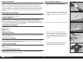
REMOVING WRINKLES
The covering of your model may develop wrinkles during shipping. Use a covering iron (HAN101) with a sealing iron
sock (HAN141) to remove them. Start with a lower heat setting and use caution while working around areas where the
colors overlap to prevent separating the colors. It is also advised to use caution around the clear windows and wing
tips as these items are plastic and could distort with excessive heat. Avoid using too much heat, which could also
separate the colors. Placing a cool damp cloth on adjacent colors will also help prevent the separation of the colors
while removing wrinkles. Only use a heat gun (HAN100) once the covering iron has been used.
BUILDING PRECAUTIONS
Prepare the work surface prior to beginning the build. The surface should be soft and free of any sharp objects. We
recommend resting the airframe parts on a soft towel or pit mat to prevent scratching or denting the surface of the
aircraft.
TRANSPORTATION AND STORAGE
When transporting and storing your model, you will need a minimum of 115 inches (3m) in length, and 32 inches
(82cm) in height to accommodate the size of the fuselage. We also recommend the use of wing and stabilizer bags to
help protect these surfaces during transport and storage. The control horns and linkages can cause damage to other
surfaces even when placed in storage bags. Always transport and store the wings and stabilizer so the linkages do not
contact other panels to prevent damage.
REPLACEMENT COVERING
Your model is covered with UltraCote® fi lm in the following colors. If repairs are required, order these coverings to
make those repairs.
HANU866 True Red
HANU870 White
HANU885 Midnight Blue
CHECKING BLIND NUTS
When building the aircraft, you will be required to thread machine screws into blind nuts. We recommend pre-threading
the screws to make sure the blind nuts are clear of any debris. If the screws do not thread in easily, clear the threads
using the appropriate tap and tap handle.
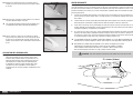
BALANCING YOUR MODEL
Due to the short nose and long tail of the Carbon Cub FX-3, it is not uncommon for them to require nose weight in
order to achieve the correct balance to suit some fl ying styles. For a soft and sedate “feel” it may be necessary to add
between 2–4 lbs (0.91–1.8 kg) to the front of the aircraft.
OPTIONAL SCALE ACCESSORIES
We have worked with various vendors to develop scale details specifi cally for this model.
Pilots:
www.warbirdpilots.com
FOR THE VISUALLY CHALLENGED
A copy of this manual can be found at www.horizonhobby.com under the tab for this particular model. Feel free to
download this manual and use a PDF viewer to zoom in on any text or images that may be in question when building
from the printed manual.
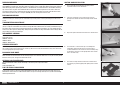
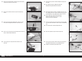
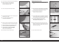
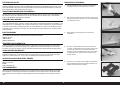
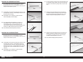
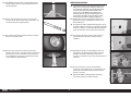
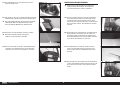
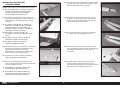
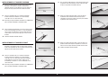
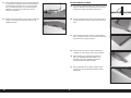
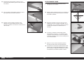
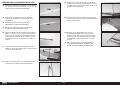
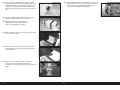
CONTROL HORN INSTALLATION
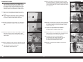
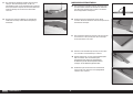
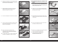
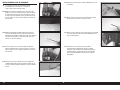
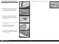
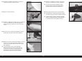
1. Use a rotary tool and sanding drum to lightly sand the
unpainted section of each control horn.
2. Test fi t the control horn in the control surface. Trim the
opening of the control horn does not fi t fully into the control
surface.
3. Repeat the process for both of the slots in the control surface.
4. Thread an M3 x 15 socket head cap screw through the
control horn. Slide a ball link on the screw, then place a
second control horn on the screw. Secure the assembly using
an M3 locknut. Leave the screw slightly loose so the control
horns can move easily.
5. Place low-tack tape around the slots of the control surface.
This will help in preventing epoxy from getting on the control
surface.

6EN
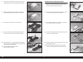
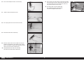
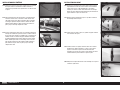
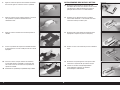
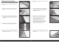
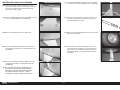
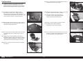
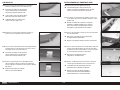
6. Apply epoxy to the unpainted area of the control horn. Make
sure to apply epoxy to the areas between the control horns.
7. Also apply epoxy to the remaining surfaces. A good bond
between the control horn and control surface is essential.
8. Place epoxy in the both slots in the control surface.
9. Insert the control horns in the control surface. Remove any
excess epoxy using a paper towel and isopropyl alcohol.
10. Before the epoxy cures, carefully remove the tape from the
control surface. Any uncured epoxy will create a fi llet between
the control horn and control surface.
Install the control horns for the elevators,
flaps and ailerons at this time.
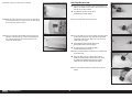
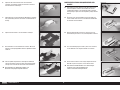
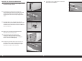
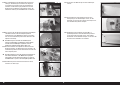
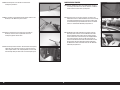
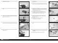
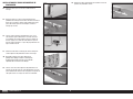
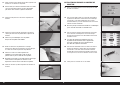
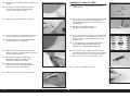
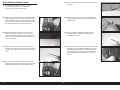
AILERON AND FLAP SERVO INSTALLATION
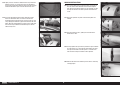
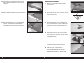
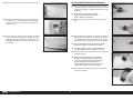
11. Remove the tape and aileron servo cover from the wing.
Make sure to re-tape the string to the wing so it can be used
to pull the extensions through the wing later.
12. Check that the servo cover and mount are glued securely. If
not, use medium CA to glue the pieces together.
13. Clear any glue or debris from the holes in the servo mount
using a drill and 5/64-inch (2mm) drill bit.
14. Thread a servo mounting screw into each of the holes to cut
threads in the surrounding wood.
15. Remove the screws, then apply a few drops of thin CA in each
hole to harden the wood.
Allow the CA to fully cure without using an accelerant.
The CA must be allowed to soak into the wood naturally.

7 EN
Carbon Cub FX-3
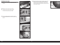
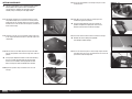
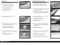
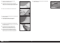
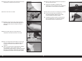
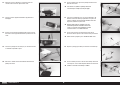
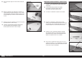
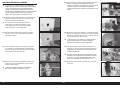
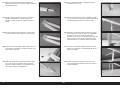
16. Place the servo into position. The output of the servo will be
centered in the slot in the servo cover.
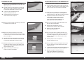
21. Use the string to pull the extension through the wing to the
wing root.
Use a helper to assist in guiding the extension
through the wing will make this task easier.
17. Secure the servo to the mount using the servo mounting
screws.
22. Slide an M3 washer on an M3 x 10 button head cap screw.
Use a toothpick to place a drop of canopy glue on the end of
the threads of the screw. Prepare four screws at this time.
Using canopy glue instead of thread lock will
allow easier removal of the screws if a servo
must be accessed at a later date.
18. Center the servo using the radio system. Secure the servo
arm to the servo perpendicular to the servo center line.
23. Use the screws to secure the servo cover in the wing. Make
sure not to cross-thread the screws in the pre-installed blind
nuts.
See note on Page 5 about checking blind nuts.
19. Secure a 36 inch (915mm) servo extension to the servo lead
using a commercially available clip.
24. Repeat the previous steps to install the fl ap servo.
20. Tie the string in the wing around the end of the servo
extension.
25. Use the string to pull the lead for the fl ap servo through the
wing. Mark the leads so they can be identifi ed easily.
Install the remaining flap and aileron servos.

8EN
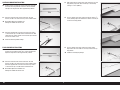
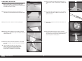
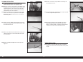
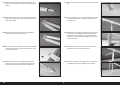
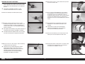
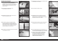
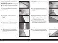
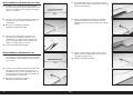
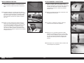
AILERON LINKAGE INSTALLATION
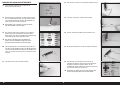
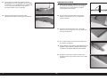
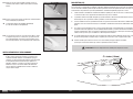
26. Remove the ball end from the aileron control horn. Assemble
the aileron link using two ball ends and a 116mm threaded
rod. Adjust the length of the rod to approximately 140mm.
31. With radio system on and the fl ap servo centered (in the mid-
fl ap position), adjust the rod to set the fl ap in the mid-fl ap
setting(1
9
/
16
inches (40mm)).
28. Attach the opposite ball end to the servo arm using an M3 x
12 socket head cap screw, M3 washer and M3 lock nut. With
radio system on and the aileron servo centered, adjust the rod
to center the aileron servo
Install the remaining aileron linkage.
27. Attach one ball end to the aileron control horn. Use two
washers, the M3 x 15 socket head cap screw and M3 locknut.
Do not over-tighten the hardware and
damage the control horn or ball end.
32. Use the radio to set the fl ap servo to the full fl ap setting (3
1
/
8
inches (80mm)). Adjust the throw at the radio as necessary to
achieve the full fl ap position.
FLAP LINKAGE INSTALLATION
29. Remove the ball end from the fl ap control horn. Assemble
the fl ap link using two ball ends and a 116mm threaded rod.
Adjust the length of the rod to approximately 150mm.
30. Attach one ball end to the aileron control horn. Use two
washers, the M3 x 15 socket head cap screw and M3 locknut.
Attach the opposite ball end to the servo arm using an M3 x
12 socket head cap screw, M3 washer and M3 lock nut.
Do not over-tighten the hardware and
damage the control horn or ball end.
33. Use the radio to set the fl ap servo to the up fl ap setting.
Adjust the throw at the radio as necessary to achieve the up
fl ap position.
Install the remaining flap linkage.

9 EN
Carbon Cub FX-3
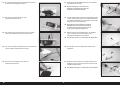
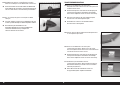
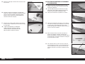
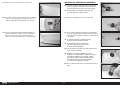
ELEVATOR SERVO INSTALLATION
34. Remove the tape, then radio cover, from the bottom of the
fuselage.
35. Remove the tape and elevator servo cover from the fuselage.
Make sure to re-tape the string to the fuselage so it can be
used to pull the extensions through the fuselage later.
36. Secure the elevator servo to the cover, Details are outlined
in the installation of the aileron servos. Secure a 36 inch
(915mm) extension to the servo lead. Install the servo arm
perpendicular to the servo center line.
37. Use the string in the fuselage to pull the elevator servo
extension through the fuselage.
Use a helper to assist in guiding the extension
through the fuselage to avoid excessive pulling and
possibly separating the string and extension.
38. Secure the elevator servo cover to the fuselage using four M3
x 10 button head screws and four M3 washers. Make sure
to place a drop of canopy glue on each screw prior to their
installation.
39. Repeat the previous steps to install the remaining elevator
servo.

10EN
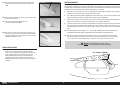
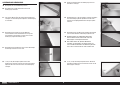
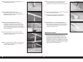
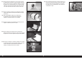
HINGING THE ELEVATORS
Do not mix any epoxy until instructed to do so.
40. Separate the elevator and stabilizer. Remove the hinges.
41. Apply a small amount of oil to the fl ex point of the hinge to
prevent epoxy from entering the hinge.
42. Insert the hinge so the center of the hinge pin aligns with the
front edge of the bevel on the control surface. Check that the
hinge can move freely.
43. Position the hinge so it is perpendicular to the hinge line
when fully defl ected.
44. Mix 1/2 ounces (15mL) of 30-minute epoxy. Remove the
hinges, then use a toothpick to apply epoxy inside each of the
holes for the hinges.
45. Apply epoxy to the outside of the hinge using a toothpick
46. Insert the hinges into the control surface. Verify the hinge
position is correct. Use a paper towel and isopropyl alcohol to
remove any excess epoxy.
47. Install all the hinges in the elevator. Allow the epoxy to fully
cure before proceeding.
The hinges in the remaining elevator can be installed
while the first set of hinges and epoxy cures.
Avoid holding the glued surfaces vertically as the epoxy may
run into the structure and settle on the inside surface of the
covering, which over time becomes visible from the outside.
48. Mix 1/2 ounces (15mL) of 30-minute epoxy. Use a toothpick
to apply epoxy inside each of the holes for the hinges.
49. Apply epoxy to the outside of the hinge using a toothpick

11 EN
Carbon Cub FX-3
50. Fit the elevator to the stabilizer. Check that the elevator can
move freely, and the hinges are all aligned properly. Use a
paper towel and isopropyl alcohol to remove any excess
epoxy.
51. Use low-tack tape to hold the two surfaces in position until
the epoxy fully cures.
The remaining elevator and stabilizer can be joined using
the hinges while the first set of hinges and epoxy cures.
ELEVATOR AND STABILIZER INSTALLATION
52. Slide the stabilizer tubes into the stabilizer tube sockets.
The shorter tube is installed toward the leading edge of the
stabilizer.
The tubes may be a tight fit in the sockets. Polishing
the tubes with fine sand paper or steel wool
will help ease the installation of the tubes.
53. Slide the stabilizer into position on the fuselage.
54. Slide the stabilizer tight against the fuselage. Secure the
stabilizer to the fuselage using two M3 x 10 button head
screws and two M3 washers. Place a drop of canopy glue on
each screw before their installation.
55. Remove the ball end from the elevator control horn. Assemble
the elevator link using two ball ends and a 75mm threaded
rod. Adjust the length of the rod to approximately 100mm.
56. Attach on ball end to the servo arm using an M3 x 12 socket
head cap screw, M3 washer and M3 lock nut. Tighten the
screw in the servo arm, then hold the screw secure while
installing the lock nut.

12EN
90˚
57. Attach the remaining ball end to the elevator control horn. Use
two M3 washers, the M3 x 15 socket head cap screw and an
M3 locknut. With the radio system on and the elevator servo
centered, adjust the linkage to center the elevator.
58. Repeat the previous steps to install the remaining stabilizer to
the fuselage and the elevator linkage.
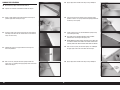
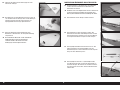
FIN INSTALLATION
59. Fit the fi n into position. Check that the fi n is 90 degrees to the
stabilizer. Lightly sand the slot in the fuselage to correct for
any alignment issues.
60. Align the trailing edge of the fi n with the fuselage. Use a felt-
tipped pen to transfer the outline of the fuselage on the fi n.
61. Remove the fi n from the fuselage. Use a felt-tipped pen to
draw a second line 1/8 inch (3mm) below the line drawn in
the previous step.
62. Use a ruler and carefully cut the covering on the lower line to
remove the covering.
Use care not to cut into the underlying wood, weakening
the fin. Use a covering iron to seal the covering to the
underlying structure before trimming the covering.
63. Remove the covering from both sides of the fi n. Remove any
lines using a paper towel and isopropyl alcohol.

13 EN
Carbon Cub FX-3
90˚
64. Mix 20g of 30-minute epoxy. Use an epoxy brush to apply
epoxy in the slot in the fuselage.
65. Use an epoxy brush to apply epoxy to the exposed wood on
the bottom of the fi n.
66. Fit the fi n back into position. Remove any excess epoxy using
a paper towel and isopropyl alcohol. Check that the fi n does
not move while the epoxy cures.
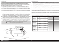
RUDDER INSTALLATION
67. Check the fi t of the rudder control horn in the slot in the
rudder.
68. View the rudder from the bottom. Make sure the control
horn is properly centered in the rudder. Check the fi t of both
control horns.
69. Remove the control horns and secure a ball end between the
control horns using an M3 x 15 socket head cap screw and
M3 lock nut. Leave the hardware slightly loose so the horns
can be manipulated during their installation.
70. Slide the control horns in the rudder. Apply epoxy to all the
points where the control horn will contact the wood of the
rudder. Slide the control horns into position and remove any
excess epoxy using a paper towel and isopropyl alcohol.
71. Install the hinges in the rudder following the steps outlined in
the elevator hinging section.
There are two holes near the bottom of the rudder. The
lower hole is for the hinge, and one slightly above it is
for the position light lead. The string for the position light
lead will be in the correct location from the factory.

14EN
72. Tape the string in the rudder to the lead for the position light.
Make sure the string is securely attached to
the lead as it will take a fair amount of force
to pull the lead through the rudder.
73. Use the string to pull the wire through the rudder.
75. Guide the lead for the position light into the fuselage. Route
the lead through the same tube as the elevator servo leads.
Remove one elevator servo and cover from the fuselage
to access the tube to install the position light lead.
There are two holes at the bottom of the fuselage.
The lower hole is for the hinge, and one slightly
above it is for the position light lead.
RUDDER SERVO INSTALLATION
77. Thread a ball end eight turns on each of the four cable
fi ttings.
78. Attach a ball link to the rudder control horn using two M3 x
15 socket head cap screws, two M3 washers and an M3 lock
nut. Install ball ends on both sides of the control horn.
Do not over-tighten the hardware and
damage the control horn or ball end.
79. Secure the rudder servo in the fuselage with the output of the
servo facing the front of the fuselage. Make sure to prepare
the servo mounting screws holes before installing the servo.
The elevator and position light leads have been
routed under the radio tray so they do not interfere
with the operation of the rudder cables.
76. Glue the hinges securing the rudder to the fi n.
74. Use a small amount of epoxy of contact adhesive to glue the
position light in the rudder.
Use care when transporting your model as
not to damage the position light.
80. Attach two of the ball ends to the rudder servo arm using
two M3 x 15 socket head cap screws, two M3 lock nuts and
two M3 washers. Tighten the hardware using a 2.5mm hex
wrench and 5.5mm nut driver.
81. Slide a sleeve on one of the cables.

15 EN
Carbon Cub FX-3
82. Pass the cable through the hole in the cable fi tting.
83. Slide the cable back through the sleeve.
84. Use crimping pliers to secure the sleeve to the cable.
85. Attach both rudder cables to the fi ttings.
87. Slide a sleeve on the cable, slide the cable through the fi tting,
then back through the sleeve. Lightly tension the cables, then
use crimping pliers to secure the sleeve to the cables. Use
side cutters to remove any excess cable.
The rudder cables may stretch slightly over
time. Periodically check the cables to make
sure there is still light tension on them.
86. Attach the rudder servo arm to the rudder servo using the
hardware included with the servo. Slide the cables into the
tubes in the fuselage. The radio system should be on and the
rudder servo centered for the following steps.
Install both sides of the cable at the same time.
This will result in equal tension on both cables.

16EN
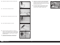
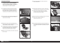
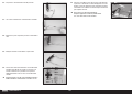
TAIL WHEEL INSTALLATION
88. Use a drill and 5/64-inch (2mm) drill bit to drill the fi rst
location for the tiller arm mounting screws.
89. Temporarily attach the tiller arm to the bottom of the rudder
with a M3 x 15 sheet metal screw. Use the tiller arm to drill
for the remaining tiller arm mount screw.
90. Remove the tiller arm from the rudder. Prepare the holes in
the bottom of the rudder by hardening the surrounding wood
with thin CA. The tiller arm can then be installed using two
M3 x 15 sheet metal screws.
91. Use the hardware included with the tail wheel to secure the
wheel in the fork. The brass spacers are located on either
side of the wheel when placed in the fork. Secure the wheel
using the M4 locknut. Use a 3mm hex wrench and 7mm nut
driver to tighten the hardware. Make sure not to over-tighten
the hardware, preventing the wheel from rotating.
92. Carefully remove the M3 nuts from the tail wheel leaf springs.
Apply a drop of thread lock on each screw. Attach the leaf
springs to the fuselage using the screws in the leaf springs.
Make sure to install the tail bracing fi tting under the forward
hole in the leaf springs.
93. Attach the springs to connect the tiller arm to the tail wheel
steering arm.

17 EN
Carbon Cub FX-3
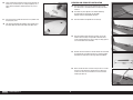
TAIL BRACING INSTALLATION
94. Slide an M3 washer, then the pre-bent aluminum cable tab on
an M3 x 25 machine screw. Slide the screw through the hole
in the top side of the stabilizer.
95. Slide a second tab on the screw from the bottom of the
stabilizer. Secure the tabs using an M3 lock nut.
Install tabs on the left and right of the
stabilizer, and near the top of the fin.
Do not overtighten the hardware and compress
the wood structure of the stabilizer or fin.
96. Thread an M3 nut on the 300mm tail bracing rod. Place a
silicone retainer on the clevis, then thread the clevis on the
rod so the end of the rod is barely visible between the forks of
the clevis. Prepare both ends of the two 300mm and 390mm
tail bracing rods.
97. Attach the clevis from the shorter 300mm tail bracing rod to
the fi tting at the tail wheel. Slide the silicone retainer over the
forks of the clevis.
99. Check that the tail bracing rod is positioned equally in both
clevises. Repeat the previous steps for the remaining 300mm
tail bracing rod on the opposite side of the stabilizer.
100. The upper 390mm tail bracing rods can be installed between
the top of the stabilizer and either side of the fi n.
98. Adjust the clevises so the opposite end can be attached to the
fi tting on the bottom of the stabilizer.
101. Check that the tail bracing does not cause any misalignment
of the stabilizer and fi n. Once set, tighten the nuts against
the clevises. Make sure to use a drop of thread lock on the
threads where the nut is positioned to prevent them from
vibrating loose.
The support wires do not need to be tight
to function properly. Adjust evenly so as
to avoid distorting the tail group.

18EN
RECEIVER INSTALLATION
102. Remove the screws holding the cockpit fl oor inside the
fuselage.
103. Mount the receiver securely in the fuselage.
The battery packs will be located next to the
fuel tank to correctly balance your model.
104. Secure the remote receivers in the fuselage. Use the
instructions provided with the receiver as a guide in their
location
105. Connect the leads for the fl aps and ailerons to the receiver.
Route the leads for the ailerons, fl aps and position light
through the hole in the cockpit fl oor. The aileron and fl ap
leads can be routed out the sides of the fuselage. Secure all
leads inside the fuselage.

19 EN
Carbon Cub FX-3
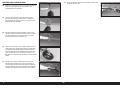
LANDING GEAR INSTALLATION
106. Attach the landing gear mounts to the fuselage using two
M4 x 20 socket head cap screws for each landing gear
mount. Place a drop of thread lock on each screw before their
installation. Attach all four mounts.
107. Attach the landing gear to the mount using two M3 x 15
socket head cap screws, four M3 washers and an M3 locknut.
108. Repeat the previous step for the remaining landing gear.
109. Attach the shock support brace to the landing gear mounts
using two M3 x 15 socket head cap screws, four M3 washers
and two M3 lock nuts.
111. Attach the shocks to the landing gear using two M3 x 25
socket head cap screws, four M3 washers and two M3 lock
nuts.
112. Use a fi le to make two fl at areas that are 1 inch (25mm) in
length on the end of the axle. Make sure the fl at areas are
opposite each other.
113. Apply a drop of light machine oil on the axle. Slide the axle
into the wheel.
114. Slide the axle into the landing gear. Secure the axle by
tightening an M3 x 3 setscrew on each of the fl at areas. Make
sure the wheel can spin freely when installed. Repeat the
previous steps for the remaining wheel.
110. Attach the shocks to the shock support brace using two M3
x 15 socket head cap screws, four M3 washers and two M3
lock nuts.
The shocks will not be able to be compressed by
hand. If so, the the spring rate and tension strength
of the shock would be too weak to support the
landing loads of a model of this size and weight.

20EN
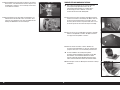
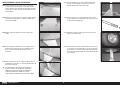
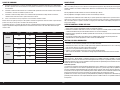
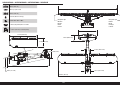
ENGINE INSTALLATION
To increase the strength of the engine mounting areas
and to stop possible compression of the wooden firewall.
There are two fiberglass plates fitted (front and rear) of
the firewall. Be aware of this when drilling for the engine
mount. Also be aware that blind nuts cannot be used to
attach the engine, as they might be on a smaller aircraft.
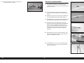
115. Place the mounting template on the fi rewall. Use a drill
and 3/32-inch (2.5mm) drill bit to drill the four holes in the
fi rewall.
When using power systems other than the recommended
choices, we advise using the mounting template as a test
to ensure hole alignment before drilling the firewall.
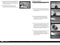
119. Attach the muffl er on the carburetor linkage side. Assemble
the linkage to operate the carburetor. Install the throttle servo
in the servo mount and position the mount so the linkage will
clear the muffl er. Make sure to mark the location of the mount
on the engine box.
116. Remove the template from the fuselage. Use a drill and 1/4-
inch (6mm) drill bit to enlarge the holes from the previous
step.
117. Attach the engine to the fuselage using four M6 x 75 socket
head cap screws, four spacers and four M6 nuts. Make
sure to use thread lock on the screws to prevent them from
vibrating loose.
118. Use the appropriate screws and spacers to achieve a spacing
of 213mm between the fi rewall and face of the drive washer.
The engine to driver washer measurement
can be between 207mm and 219 mm.
120. Remove the servo from the servo mount, and the muffl er from
the engine. Use 30-minute epoxy to glue the servo mount to
the engine box. Make sure the servo mount does not move
while the epoxy cures.
The cover can also removed for the installation of
internal canister type mufflers. If stock mufflers
are fitted the cover can either be left on or off.
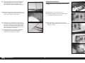
121. Once the epoxy cures, install the throttle servo and linkage. A
choke servo can also be mounted in the servo mount. Check
the operation of the servos using the radio system.
The choke access can be accessed by fitting a
hand through the front cowling intake hole. Be sure
to check if your hand is small enough to fit into
the cowling before committing to this option.
122. Remove the cover behind the throttle servos and set the
screws aside.
La pagina sta caricando ...
La pagina sta caricando ...
La pagina sta caricando ...
La pagina sta caricando ...
La pagina sta caricando ...
La pagina sta caricando ...
La pagina sta caricando ...
La pagina sta caricando ...
La pagina sta caricando ...
La pagina sta caricando ...
La pagina sta caricando ...
La pagina sta caricando ...
La pagina sta caricando ...
La pagina sta caricando ...
La pagina sta caricando ...
La pagina sta caricando ...
La pagina sta caricando ...
La pagina sta caricando ...
La pagina sta caricando ...
La pagina sta caricando ...
La pagina sta caricando ...
La pagina sta caricando ...
La pagina sta caricando ...
La pagina sta caricando ...
La pagina sta caricando ...
La pagina sta caricando ...
La pagina sta caricando ...
La pagina sta caricando ...
La pagina sta caricando ...
La pagina sta caricando ...
La pagina sta caricando ...
La pagina sta caricando ...
La pagina sta caricando ...
La pagina sta caricando ...
La pagina sta caricando ...
La pagina sta caricando ...
La pagina sta caricando ...
La pagina sta caricando ...
La pagina sta caricando ...
La pagina sta caricando ...
La pagina sta caricando ...
La pagina sta caricando ...
La pagina sta caricando ...
La pagina sta caricando ...
La pagina sta caricando ...
La pagina sta caricando ...
La pagina sta caricando ...
La pagina sta caricando ...
La pagina sta caricando ...
La pagina sta caricando ...
La pagina sta caricando ...
La pagina sta caricando ...
La pagina sta caricando ...
La pagina sta caricando ...
La pagina sta caricando ...
La pagina sta caricando ...
La pagina sta caricando ...
La pagina sta caricando ...
La pagina sta caricando ...
La pagina sta caricando ...
La pagina sta caricando ...
La pagina sta caricando ...
La pagina sta caricando ...
La pagina sta caricando ...
La pagina sta caricando ...
La pagina sta caricando ...
La pagina sta caricando ...
La pagina sta caricando ...
La pagina sta caricando ...
La pagina sta caricando ...
La pagina sta caricando ...
La pagina sta caricando ...
La pagina sta caricando ...
La pagina sta caricando ...
La pagina sta caricando ...
La pagina sta caricando ...
La pagina sta caricando ...
La pagina sta caricando ...
La pagina sta caricando ...
La pagina sta caricando ...
La pagina sta caricando ...
La pagina sta caricando ...
La pagina sta caricando ...
La pagina sta caricando ...
La pagina sta caricando ...
La pagina sta caricando ...
La pagina sta caricando ...
La pagina sta caricando ...
La pagina sta caricando ...
La pagina sta caricando ...
La pagina sta caricando ...
La pagina sta caricando ...
La pagina sta caricando ...
La pagina sta caricando ...
La pagina sta caricando ...
La pagina sta caricando ...
La pagina sta caricando ...
La pagina sta caricando ...
La pagina sta caricando ...
La pagina sta caricando ...
La pagina sta caricando ...
La pagina sta caricando ...
La pagina sta caricando ...
La pagina sta caricando ...
La pagina sta caricando ...
La pagina sta caricando ...
La pagina sta caricando ...
La pagina sta caricando ...
-
 1
1
-
 2
2
-
 3
3
-
 4
4
-
 5
5
-
 6
6
-
 7
7
-
 8
8
-
 9
9
-
 10
10
-
 11
11
-
 12
12
-
 13
13
-
 14
14
-
 15
15
-
 16
16
-
 17
17
-
 18
18
-
 19
19
-
 20
20
-
 21
21
-
 22
22
-
 23
23
-
 24
24
-
 25
25
-
 26
26
-
 27
27
-
 28
28
-
 29
29
-
 30
30
-
 31
31
-
 32
32
-
 33
33
-
 34
34
-
 35
35
-
 36
36
-
 37
37
-
 38
38
-
 39
39
-
 40
40
-
 41
41
-
 42
42
-
 43
43
-
 44
44
-
 45
45
-
 46
46
-
 47
47
-
 48
48
-
 49
49
-
 50
50
-
 51
51
-
 52
52
-
 53
53
-
 54
54
-
 55
55
-
 56
56
-
 57
57
-
 58
58
-
 59
59
-
 60
60
-
 61
61
-
 62
62
-
 63
63
-
 64
64
-
 65
65
-
 66
66
-
 67
67
-
 68
68
-
 69
69
-
 70
70
-
 71
71
-
 72
72
-
 73
73
-
 74
74
-
 75
75
-
 76
76
-
 77
77
-
 78
78
-
 79
79
-
 80
80
-
 81
81
-
 82
82
-
 83
83
-
 84
84
-
 85
85
-
 86
86
-
 87
87
-
 88
88
-
 89
89
-
 90
90
-
 91
91
-
 92
92
-
 93
93
-
 94
94
-
 95
95
-
 96
96
-
 97
97
-
 98
98
-
 99
99
-
 100
100
-
 101
101
-
 102
102
-
 103
103
-
 104
104
-
 105
105
-
 106
106
-
 107
107
-
 108
108
-
 109
109
-
 110
110
-
 111
111
-
 112
112
-
 113
113
-
 114
114
-
 115
115
-
 116
116
-
 117
117
-
 118
118
-
 119
119
-
 120
120
-
 121
121
-
 122
122
-
 123
123
-
 124
124
-
 125
125
-
 126
126
-
 127
127
-
 128
128


Hangar 9 HAN5280 Manuale del proprietario
- Categoria
- Giocattoli telecomandati
- Tipo
- Manuale del proprietario
in altre lingue
- English: Hangar 9 HAN5280 Owner's manual
- français: Hangar 9 HAN5280 Le manuel du propriétaire
- Deutsch: Hangar 9 HAN5280 Bedienungsanleitung
Documenti correlati
-
 Hangar 9 HAN5260 Manuale del proprietario
-
 Hangar 9 HAN5065 Manuale del proprietario
-
 Hangar 9 HAN4670 Manuale del proprietario
-
Evolution 33cc Manuale del proprietario
-
 Hangar 9 HAN4720CR Manuale del proprietario
-
 Hangar 9 HANGAR 9 Ultra Stick 30cc Manuale del proprietario
-
 Hangar 9 HAN4770 Manuale del proprietario
-
 Hangar 9 HAN2345 Manuale del proprietario
-
 Hangar 9 HAN3390 Manuale utente
-
 Hangar 9 HAN2530 Manuale del proprietario


Altri documenti
-
E-flite Habu 32x DF Manuale utente
-
-
Kyosho 11892 Manuale utente
-
Spektrum SPMSA6380 Manuale del proprietario
-
Blade SR UH-1 Manuale utente
-
-
-
Garmin GRF 10 Rorfeedback-sensor Guida d'installazione
-
Petsafe Staywell 400 Series Guida d'installazione