Greyline Instruments DFM 5.0 Manuale utente
- Tipo
- Manuale utente


IMPORTANT NOTE: This instrument is manufactured and calibrated to meet product specifications.
Please read this manual carefully before installation and operation. Any unauthorized repairs or
modifications may result in a suspension of the warranty.
If this product is not used as specified by the manufacturer, protection may be impaired.
Available in Adobe Acrobat pdf format
Page 3
DFM 5.0 Doppler Flow Meter
INDEX
Connections ......................................................4
Keypad System ....................................................6
Calibration Menu ..................................................7
Message .........................................................8
Status............................................................8
Password .........................................................9
Units/Mode ......................................................10
Calibration ......................................................11
Relay Parameters .................................................12
Special Functions .................................................13
Sensor Mounting..................................................15
Enclosure Installation ..............................................19
Synchronization ..................................................20
Troubleshooting ..................................................21
Common Questions And Answers ....................................24
Applications Hotline ...............................................26
Product Return Procedure ...........................................27
Warranty ........................................................29
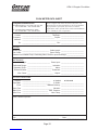
Flow Meter Data Sheet .............................................28
Warranty ........................................................29
Appendix A – Options .............................................30
Data Logger .....................................................36
Specifications ....................................................38
Appendix B - Conversion Table ......................................39
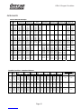
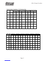
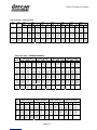
Pipe Charts ......................................................40

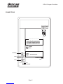
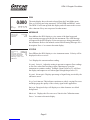
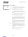
CONNECTIONS:
POWER INPUT: The standard model requires AC power input between 100 to 240 VAC 50/60Hz . No
adjustments are necessary for voltages within this range.
Optional DC input model requires 9-32 VDC/7 Watts. Connect to + and −terminals. Connect L (Live)
N (Neutral) and AC Ground.
Optional Thermostat and Heater modules are available rated for 115 VAC or 230 VAC.
IMPORTANT NOTE: To comply with CSA/UL electrical safety standards, AC power input and relay
connection wires must have conduit entry to the instrument enclosure. Installation requires a switch,
overcurrent fuse or circuit breaker in the building (in close proximity to the equipment) that is marked
as the disconnect switch.
Risk of electric shock. Loosen cover screw to access connections. Only qualified personnel
should access connections.
Note: Use of instrumentation over 40°C ambient requires special field wiring.
Note: User replaceable fuse is 2 Amp 250V (T2AL250V).
Page 4
DFM 5.0 Doppler Flow Meter
!


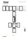
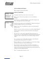
KEYPAD SYSTEM
The following diagram shows the DFM 5.0 menu system. Arrows show the four directions to leave a
menu box. Pressing a corresponding keypad arrow will move to the next item in the direction shown.
Move the cursor (underline) under numerals and increase or decrease numerals with the Çand Èkeys.
To store calibration values permanently (even through power interruptions), press the ü.
DFM 5.0 Doppler Flow Meter
Page 6

CALIBRATION MENU
Page 7
DFM 5.0 Doppler Flow Meter
--Password----------
Password 0000
--Data Logging-------
>Log Site ID 0
Mode Flow
Set Date Feb 18/2007
Set Time 11:27:40
Interval 10sec
Reset Log NO
--Units/Mode--------
>Mode Flow
Linear in
Volume USG
Time min
--Calibration-------
>20mA at 2500.0 USG/m
4mA at 0.000 USG/m
Pipe ID 12.00in
Damping 20%
--Relay Parameters--
>Relay 1
Function Flow
Mode Pump
On 1000 USG
Off 0.000 USG
USG/min
Tot 20130.8 USG
Relays 123456
0.000
--Message-----------
Data log Logging
Log Use 0%
Sensor Good
--24 hr log----------
>Date Feb. 12/2008
Total 0.000ft/s
Average 0.000ft/s
Maximum 0.000ft/s
Max Time 01:57:00
Minimum -1.046ft/s
Min Time 02:35:00
--Status------------
>Velocity 0.00ft/s
Tot 0.000USG
Signal Cutoff 5%
Signal Strength 0%
Sig Confidence 0
Relays123456
20mA at
--Special Functions-
>Language English
Backlight On High
Reset Totalizer NO
Negative Totals NO
Reverse Flow NO
Cal Constant 1.000
Restore Defaults NO
New Password 0000
--Simulation--------
>Output 250USG
4-20mA 5.60mA
Relays 1 23456
--Configuration-----
>Utility Board 1.01
Doppler 1.02
Logger 1.03T
Relays 2
4-20 Outputs 1
--Menu Selections----
>Units / Mode
Calibration
Relay Parameters
Data Logging
Special Functions
Simulation
Configuration
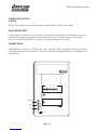
OPTIONAL FEATURES

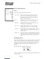
RUN
The main display shows the units selected from the Units/Mode menu,
Flow or Velocity rate being measured, TOTALIZER and RELAY states.
The DFM 5.0 will start-up with this display and will return to this screen
after a timeout if keys are not pressed in other menus.
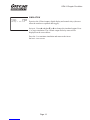
MESSAGE
Press Çfrom the RUN display to view status of the data logger and
error/warning messages provided by the instrument. The word Message
will appear on the RUN display if error messages are being generated by
the instrument. Refer to the manual section Error/Warning Messages for a
description. Press üto return to the main display.
STATUS
Press Èfrom the RUN display to view instrument status. Velocity will be
displayed in ft/sec or m/sec.
Tot Displays the current totalizer reading.
Signal Cutoff Adjust the setting in percent to suppress flow readings
at zero flow when fluid swirling or pipe vibration may cause the
instrument to continue reading. Example: Signal Cutoff at 5% will force
the display and outputs to zero when signal strength drops below 5%.
Signal Strength Displays percentage of signal being received by the
ultrasonic sensor.
Sig Confidence This indicates consistent or widely varying flow rates
and helps gauge the quality of the velocity signal in the application.
Relays Energized relays will display as a white character on a black
background.
20mA at Displays the flow rate set as 20mA in the Calibration menu.
Press üto return to the main display.
Page 8
DFM 5.0 Doppler Flow Meter
--Message-----------
Data log Logging
Log Use 0%
Sensor Good
--Status------------
>Velocity 0.00ft/s
Tot 0.000USG
Signal Cutoff 5%
Signal Strength 0%
Sig Confidence 0
Relays123456
20mA at
USG/min
Tot 20130.8 USG
Relays 123456
0.000

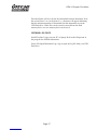
24 HR LOG (Data Logging option only)
Press Åfrom the RUN display to view a formatted flow report from
instruments with a built-in data logger. Press Èto scroll down one day or
repeatedly to scroll to a specific date. Up to 365 days can be stored.
Newest date will overwrite the oldest. Press üto return to the main
display.
PASSWORD
The password (a number from 0000 to 9999) prevents unauthorized access
to the Calibration menu.
From the Run display press the Ækey to get to Password. Factory
default password is 0000 and if it has not been changed press the üto
proceed to the Menu Selections screen.
If a password is required, press Æto place the cursor under the first digit
and Èor Çto set the number, then Æto the second digit, etc. Press Æor
üto proceed to the Menu Selections screen.
A new password can be stored by going to Special Functions/New
Password.
Page 9
DFM 5.0 Doppler Flow Meter
--Password----------
Password 0000
--24 hr log----------
>Date Feb. 12/2008
Total 0.000ft/s
Average 0.000ft/s
Maximum 0.000ft/s
Max Time 01:57:00
Minimum -1.046ft/s
Min Time 02:35:00

UNITS/MODE
From >Mode press the Æand then the Çor Èto select Flow or
Velocity. Flow mode displays the flow rate in engineering units (e.g.
gpm, litres/sec, etc.) Press the üto store your selection then the Èto the
next menu item and Æto enter.
From >Linear press the Ækey and then the Çor Èto select your units
of measurement. Press the üto store your selection.
Press the Èkey to move the >symbol to each subsequent menu item and
the üto save your selections.
Note: the volume selection "bbl" denotes U.S. oil barrel.
Press Åor üto return to the Menu Selections screen.
Page 10
DFM 5.0 Doppler Flow Meter
--Units/Mode--------
>Mode Flow
Linear in
Volume USG
Time min
--Units/Mode--------
Mode Flow
>Linear i
ft
m
mm
n
--Units/Mode--------
>Volume US
ft3
bbl
L
m3
IMG
IG
USMG
G
--Units/Mode--------
Mode Flow
Linear in
Volume USG
>Time se
day
hr
min
c

CALIBRATION
Press the Èto >Calibration and Æto enter. Use Èor Çto position
>before each menu item and Æto enter. When settings are completed
press üto store and return to the Calibration menu
20mA at Press Æthen Èor Çto change the numbers and decimal point.
Use this menu to set the corresponding flow rate that will be represented
by 20mA analog output. If maximum flow is unknown, enter an estimated
flow rate and observe actual flow to determine the correct maximum
value. Any velocity or flow rate up to +40 ft/sec (12.2 m/sec) may be
selected.
4mA at Press Èor Çto set the flow rate corresponding to 4mA analog
output. This setting may be left at zero flow (or velocity or can be raised
to any value less than the 20mA setting, or lowered to any velocity or
corresponding flow rate down to -40 ft/sec (-12.2 m/sec).
Pipe ID Place the cursor under the digits and then Èor Çto change the
numbers and decimal point. Pipe ID should be entered as the exact
inside diameter of the pipe where the sensor is mounted. Refer to the Pipe
Charts Appendix in this manual for inside diameter of common pipe types
and sizes.
Damping - Increase damping to stabilize readings under turbulent flow
conditions. Decrease for fast response to small changes in flow. Damping
is shown in percentage (maximum is 99%). Factory default is 20%.
Press üfrom the Units/Mode display to return to Menu Selections.
Page 11
DFM 5.0 Doppler Flow Meter
--Calibration-------
>20mA at 2500.0 USG/m
4mA at 0.000 USG/m
Pipe ID 12.00in
Damping 20%

RELAY PARAMETERS
Relay Press Æand Èor Çto select a corresponding relay
number (2 relays are standard, 4 additional are optional).
Function Press Èor Çto select Off,Pulse or Flow.
Flow Mode Select Pump,Low Alarm or Hi Alarm.
Pump mode provides separate On/Off settings where the
relay will energize at one flow rate and de-energize at
another.
On Position the cursor under the numerals and press Èor
Çto set digits to the required relay On set point.
Off set digits to the required Off set point.
Low Alarm mode relay will energize at a programmable
flow rate and remain energized with flow below the set
point. When flow rises above the set point, the relay will
de-energize.
Hi Alarm mode relay will energize at a programmable
flow rate and remain energized with flow above the set
point. When flow falls below the set point, the relay will
de-energize.
Pulse Press Èand set digits to the flow volume increment
required between relay pulses. Use this feature for remote
samplers, chlorinators or totalizers. Minimum time
between pulses is 2.25 seconds and pulse duration is 350
milliseconds.
Return to Relay and change settings for each relay
number.
Press üto return to Menu Selections.
Page 12
DFM 5.0 Doppler Flow Meter
--Relay Parameters--
>Relay 1
Function Flow
Mode Pump
On 1000 USG
Off 0.000 USG

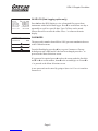
DATA LOGGING (OPTIONAL)
Refer to Options section of this manual.
SPECIAL FUNCTIONS
Language Select English,French or Spanish
Backlight Select On High,Medium or Low for continuous
backlight.
Select Key Hi/Lo for high backlight for 1 minute after a keypress and
then Lo backlight until a key is pressed again.
Select Key High,Med or Low for backlight for 1 minute after a keypress
and then backlight off until a key is pressed again.
Reset Totalizer Press Æand select Yes to erase and restart the
totalizer at zero.
Negative Totals Select Yes to have reverse flow readings deducted
from the totalizer. Select No to totalize forward flow only and ignore
reverse flow.
Reverse Flow Select Yes to change the display from positive or
negative values (e.g. sensor mounted in a direction that shows normal flow
as negative values. Use Reverse Flow to change readings to positive
values.)
Cal Constant Set to 1.000 for SE4-A transducer. (Note: Different
transducer models require specific Cal Constants.)
Restore Defaults Select Yes and press üto erase all user settings
and return the instrument to factory default settings.
New Password Select any number from 0000 to 9999 and press ü.
Default setting of 0000 will allow direct access to the calibration menus.
Setting of any password greater than 0000 will require the password to be
entered to access the calibration menus.
Press üto return to Menu Selections.
Page 13
DFM 5.0 Doppler Flow Meter
--Special Functions-
>Language English
Backlight On High
Reset Totalizer NO
Negative Totals NO
Reverse Flow NO
Cal Constant 1.000
Restore Defaults NO
New Password 0000
--Special Functions-
Language English
>Backlight On Hig
On Med
On Low
Key Hi/Lo
Key High
Key Med
Key Lo
Off
h

SIMULATION
Exercises the 4-20mA output, digital display and control relays (does not
affect the totalizer or optional data logger).
Output Press Æand then Èor Çto change the simulated output. Press
üto begin simulation. The 4-20mA output and relay states will be
displayed on the screen below.
Press the üto terminate simulation and return to the Menu
Selections screen.
Page 14
DFM 5.0 Doppler Flow Meter
--Simulation--------
>Output 250USG
4-20mA 5.60mA
Relays 1 23456

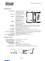
SENSOR MOUNTING LOCATION
The position of the sensor is one of the most important considerations for accurate Doppler flow
measurement. The same location guidelines apply to Doppler as most other types of flow meters.
Before permanently mounting a Doppler sensor onsite testing is recommended to determine optimum
mounting position. Use the sensor coupling compound (supplied with each Greyline flow meter, or
petroleum gel, acoustic compound or electrocardiograph gel). Take several readings around the axis of
the pipe and then at several points upstream and downstream from the selected position, checking for
consistent readings. Avoid high or low reading areas. Mount the sensor where consistent (average)
readings were obtained or continue testing on another pipe section.
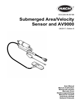
VERTICAL OR HORIZONTAL PIPE - Vertical pipe
runs generally provide evenly distributed flow. On
Horizontal pipes and liquids with high concentrations
of gas or solids, the sensor should be mounted on the
side (3 or 9 o’clock position) to avoid concentrations
of gas at the top of the pipe, or solids at the bottom.
For liquids with minimal gas bubbles (e.g. potable
water) the sensor should be mounted on the top of a
horizontal pipe (12 o’clock position) to obtain the best
signal strength.
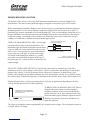
VELOCITY INCREASING DEVICES: Generally the sensor must be mounted away from flow
disturbances such as valves, pumps, orifice plates, venturis or pipe inlets and discharges which tend to
increase flow velocity. Velocity increasing devices often cause cavitation, or rapid release of gas
bubbles, and readings both up and downstream may show much higher velocity. As a guideline, mount
the sensor at least 20 diameters upstream or 30 diameters downstream from velocity increasing devices.
Required distance from a velocity increasing device will vary in applications depending on the flow
velocity and the characteristics of the liquid itself.
TURBULENCE INCREASING DEVICES: Elbows,
flanged connections and tees tend to introduce
desirable conditions of an evenly distributed flow
profile with some air or gases entrained in the flow.
Sensor mounting 6 pipe diameters upstream and 10
diameters downstream from these disturbances is
generally optimum.
The sensor is designed to mount longitudinally on a straight section of pipe. Do not attempt to mount it
on bends, elbows or fittings.
Page 15
DFM 5.0 Doppler Flow Meter
VERTICAL PIPE USUALLY
HAS EVENLY DISTRIBUTED FLOW
12 O'CLOCK POSITION WITH
LOW GAS CONTENT
3 O'CLOCK POSITION WITH HIGH
GAS OR SOLIDS CONTENT
FLOW
SENSOR MOUNTS 6 DIAMETERS
UPSTREAM OR 10 DOWNSTREAM
FROM AN ELBOW

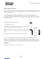
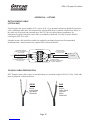
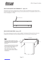
SENSOR MOUNTING
Prepare an area 2" wide by 4" long (50mm x 100mm) for sensor bonding by removing loose paint, scale
and rust. The objective of site preparation is to eliminate any discontinuity between the sensor and the
pipe wall, which would prevent acoustical coupling.
A PC4 Sensor Mounting Kit is supplied with each Greyline flow meter. It includes recommended
coupling compound in a plastic applicator and a stainless steel mounting bracket with adjustable pipe
straps.
Page 16
DFM 5.0 Doppler Flow Meter
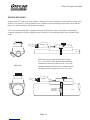
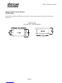
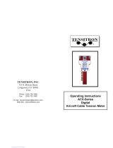
PIPE
Mount the PC4 pipe clamp as illustrated on pipes
0.6" / 15 mm OD or larger. Stainless steel bands are
included for mounting on pipes up to 32" / 81 cm OD.
Additional stainless steel bands (by customer) may be
combined to mount on pipes up to 180" / 4.5 m OD.
END VIEW
SENSOR
ADJUSTABLE
STAINLESS
STEEL STRAP
PIPE
PIPE
SENSOR
PIPE

SENSOR COUPLING
For permanent or temporary bonding, the following are recommended:
a) Dow Corning silicon compound #4 (supplied)
Additional supply: order Greyline Option CC
b) High Temperature compound (supplied with Sensor Option SE3H)
Additional supply: order Greyline Option AP-1W
c) Water-based sonic compound: Order Greyline Option CC30
d) Electrocardiograph gel
e) Petroleum gel (Vaseline)
The above are arranged in their order of preferred application.
d & e are only good for temporary bonding at room temperature.
DO NOT USE: Silicon RTV caulking compound (silicon rubber).
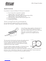
Use the PC4 pipe clamp (supplied) as illustrated above or
use a loop of electrical tape for temporary mounting.
Apply silicon coupling compound #4 to the coloured face
of the sensor. A bead, similar to toothpaste on a
toothbrush, is ideal. Do not overtighten (crush the
sensor).
The sensor must be fixed securely to the pipe with coupling material
between the sensor face and the pipe. Sensor installation with
excessive coupling compound can result in gaps or voids in the
coupling and cause errors or loss of signal. Insufficient coupling
compound will create similar conditions.
Over time temporary coupling compounds (e.g. Petroleum Gel) may
gradually sag away from the sensor resulting in reduced signal
strength and finally complete loss of signal. Warm temperatures, moisture and vibration will accelerate
this process. Dow Corning Silicone Compound #4 as supplied with the DFM 5.0 (and available from
Greyline Instruments) is recommended for semi-permanent installations.
Page 17
DFM 5.0 Doppler Flow Meter
COMPOUND
SENSOR
TAPE OR
CLAMP
C
O
MP
O
UND
PIPE
SENSOR


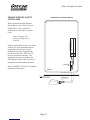
ENCLOSURE INSTALLATION
Locate the enclosure within 20 ft (6 m) of the sensor (500 ft -150 m optional). The enclosure can be wall
mounted with the four mounting screws (included) or panel mounted with Option PM Panel Mount kit
from Greyline Instruments.
Avoid mounting the enclosure in direct sunlight to protect the electronics from damage due to
overheating and condensate. In high humidity atmospheres, or where temperatures fall below freezing,
Option TH Enclosure Heater and Thermostat is recommended. Seal conduit entries to prevent moisture
from entering enclosure.
NEMA4X (IP66) WITH CLEAR COVER
1. Open hinged enclosure cover.
2. Insert #8 screws (supplied) through the four enclosure mounting holes
to secure the enclosure to the wall or mounting stand.
Additional conduit holes can be cut in the bottom of the enclosure when
required. Use a hole saw or Greenlee-type hole cutter to cut the required
holes.
DO NOT make conduit/wiring entries into the top of the enclosure.
Note: This non-metallic enclosure does not automatically provide grounding between conduit
connections. Grounding must be provided as part of the installation. Ground in accordance with the
requirements of the National Electrical Code. System grounding is provided by connecting grounding
wires from all conduit entries to the steel mounting plate or another point which provides continuity.
CLEANING
Cleaning is not required as a part of normal maintenance.
Page 19
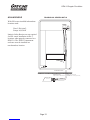
DFM 5.0 Doppler Flow Meter
END VIEW
COVER
ENCLOSURE
ENCLOSURE
MOUNTING
HOLES

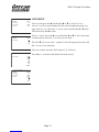
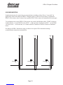
SYNCHRONIZATION
Synchronization may be required to prevent interference (readings with no flow or "cross talk") in
applications where more than one DFM 5.0 Doppler sensor is used in close proximity. Synchronize
DFM 5.0 flow meters only if sensors from separate DFM 5.0 flow meters are mounted on the same pipe.
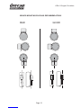
To synchronize one or more DFM 5.0 flow meters use twisted, shielded pair cable, 22AWG or heavier.
Connect SYNC + of one DFM 5.0 to the SYNC + of the next unit. And connect SYNC - of one DFM
5.0 to the SYNC - of the next unit, etc. Connect shield to Transducer GND on all units as illustrated
below.
No changes in DFM 5.0 hardware setup or software are required. The instruments manage
synchronization connections automatically.
Page 20
DFM 5.0 Doppler Flow Meter
–+
SYNC
TRANSDUCER
GND
–+
SYNC
TRANSDUCER
GND
–+
SYNC
TRANSDUCER
GND
La pagina sta caricando ...
La pagina sta caricando ...
La pagina sta caricando ...
La pagina sta caricando ...
La pagina sta caricando ...
La pagina sta caricando ...
La pagina sta caricando ...
La pagina sta caricando ...
La pagina sta caricando ...
La pagina sta caricando ...
La pagina sta caricando ...
La pagina sta caricando ...
La pagina sta caricando ...
La pagina sta caricando ...
La pagina sta caricando ...
La pagina sta caricando ...
La pagina sta caricando ...
La pagina sta caricando ...
La pagina sta caricando ...
La pagina sta caricando ...
La pagina sta caricando ...
La pagina sta caricando ...
-
 1
1
-
 2
2
-
 3
3
-
 4
4
-
 5
5
-
 6
6
-
 7
7
-
 8
8
-
 9
9
-
 10
10
-
 11
11
-
 12
12
-
 13
13
-
 14
14
-
 15
15
-
 16
16
-
 17
17
-
 18
18
-
 19
19
-
 20
20
-
 21
21
-
 22
22
-
 23
23
-
 24
24
-
 25
25
-
 26
26
-
 27
27
-
 28
28
-
 29
29
-
 30
30
-
 31
31
-
 32
32
-
 33
33
-
 34
34
-
 35
35
-
 36
36
-
 37
37
-
 38
38
-
 39
39
-
 40
40
-
 41
41
-
 42
42


Greyline Instruments DFM 5.0 Manuale utente
- Tipo
- Manuale utente
in altre lingue
Documenti correlati
Altri documenti
-
 Hach AV9000S Manuale utente
-
ProMinent DULCO flex Control-DFYa Operating Instructions Manual
-
-
 TENSITRON ACX-Series Operating Instructions Manual
-
Aeroflex 2051T Istruzioni per l'uso
-
red lion IMP Manuale utente
-
Carel heaterSteam Manuale utente
-
-
Daniel Model 2271 Flow Computer Manuale del proprietario
-
Hach Flo-Dar Basic User Manual

