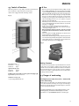
Jotul F 371 Manuale del proprietario
- Categoria
- Camini
- Tipo
- Manuale del proprietario

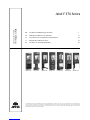
Jøtul F 370 Series
GB - Installation and Operating Instructions 2
FR - Manuel d’installation et d´utilisation 22
ES - Instrucciones para instalación y mantenimiento 42
IT - Manuale di installazione ed uso 62
NL - Installatie- en montagehandleiding 82
Jøtul F 370 Series
Manual Version P02
The manuals which are enclosed with the product must be kept throughout the product’s entire service life. Les manuels fournis avec le produit doivent être
conservés pendant toute la durée de vie du produit. Los manuales suministrados con este producto deben guardarse durante todo el ciclo de vida del producto.
I manuali inclusi con il prodotto vanno conservati per l’intera durata di vita del prodotto. De bij de haard meegeleverde handleidingen moeten gedurende de
volledige gebruiksduur van de haard bewaard blijven.
Jøtul F 371 Jøtul F 373 Jøtul F 374 Jøtul F 375 Jøtul F 376 Jøtul F 377 Jøtul F 379

2
Table of contents
Installation manual with technical data
1.0 Relationship to the authorities ................... 2
2.0 Technical data .............................................. 2
3.0 Safety ............................................................ 3
4.0 Installation ..................................................8
5.0 Daily use ......................................................18
6.0 Maintenance ...............................................18
7.0 Service ......................................................... 19
8.0 Operational problemes -
troubleshooting .........................................20
9.0 Optional Equipment ..................................20
10.0 Warranty ......................................................21
1.0 Relationship to the
authorities
Installation of a fireplace must be according to local codes and
regulations in each country.
All local regulations, including those which refer to national
and European standards, must be observed when installing the
product.
The installation can only be put into use after it has been checked
by a qualified inspector. Contact your local building authorities
before installing a new fireplace.
A product data plate of heat-resistant material is affixed to the
product. This contains information about identification and
documentation for the product.
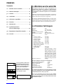
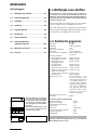
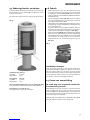
2.0 Technical data
Material: Cast iron
Finish: Black or grey varnish
Fuel: Wood
Log length, max.: 30 cm
Flue outlet: Top, rear
Flue pipe dimension: Ø150 mm/min. 177 cm2 cross
section
Approx. weight:
- with cast iron base: Approx. 163 kg
- with cast iron pedestal: Approx. 156 kg
- with cast iron leg: Approx. 154 kg
- with cast iron base
and glass door: Approx. 165 kg
- with glass base: Approx. 158 kg
- Jøtul F 377 with soapstone: Approx. 220 kg
- Jøtul F 377 HT with soapstone: Approx. 270 kg
- Jøtul F 377 with heat storage
system and soapstone: Approx. 330 kg
- with three legs: Approx. 149 kg
Optional extras: Decoration plates, cover for
side windows, rotating set
(Jøtul 373), glass decoration
- top/sides/front, soap stone -
top, wood store, cast iron door
for base (Jøtul F 371), High
Top, Jøtul F 377 soapstone,
Jøtul F 377 HT soapstone,
convection kit, heat storage
system
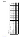
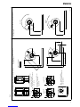
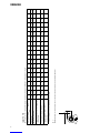
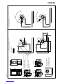
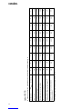
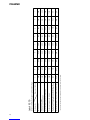
Dimensions, distances: See fig. 1
Technical data according to EN 13240
Nominal heat output: 5,5 kW
Flue gas mass flow: 5,9 g/s
Recommended chimney draught: 12 Pa
Efficiency: 73%@5,8 kW
CO emission (13% O2): 0.12%
Flue gas temperature: 330o C
Operational type: Intermittent
Intermittent combustion in this context means normal use of the
fireplace, i.e. fuel is added as soon as the fuel has burnt down to
a suitable amount of embers.
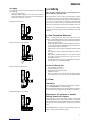
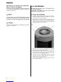
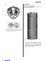
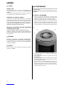
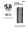
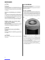
On all our products there is a label
indicating the serial number and
year. Write this number in the
place indicated in the installation
instructions.
Always quote this serial number when
contacting your retailer or Jøtul.
les combustibles recommandés.
Respectez les consignes d'utilisation. Utilisez uniquement
Verwenden Sie nur empfohlenen Brennstoffen.
Montage- und Bedienungsanleitung beachten.
Follow user`s instructions. Use only recommended fuels.
standard
Certificate/
The appliance can be used in a shared flue.
Minimum distance to adjacent combustible materials:
Emission of CO in combustion products
Serial no: Y-xxxx, Year: 200x
Manufacturer:
N-1602 Fredrikstad
Norway
Jøtul AS
POB 1441
Sweden
EUR Intermittent
Nominal heat output
Norway
Country
Operational type
Fuel type
Operation range
Efficiency
Klasse II
Classification
Standard
Flue gas temperature
Room heater fired by solid fuel
Product:
Jøtul
SP Sveriges Provnings- och
221546
Forskningsinstitut AB
SP Swedish National
Testing and Research
Institute
:
Approved by
:
:
:
:
:
:
:
Minimum distance to adjacent combustible materials:
OGC SP
EN
Serial no.
ENGLISH

3
ENGLISH
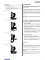
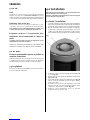
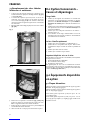
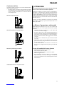
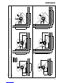
Air supply
The outside air connection may be fitted directly to the Jøtul F 370
Series through:
• The base/pedestal/leg or
• through a flexible supply hose from the outside/chimney
(only if the chimney has its own duct for external air) and to
the product’s outside air connector.
Through an outside wall
Through the floor and ground plate
Through the floor and basement
Indirectly through an outside wall
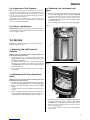
3.0 Safety
NB! To guarantee optimal performance and safety, Jøtul stoves
must be fitted by a qualified installer.
Any modifications to the product by the distributor, installer
or consumer may result in the product and safety features not
functioning as intended. The same applies to the installation of
accessories or optional extras not supplied by Jøtul. This may
also be the case if parts that are essential to the functioning
and safety of the fireplace have been disassembled or removed.
In all these cases, the manufacturer is not responsible or liable
for the product and the right to make a complaint becomes null
and void.
3.1 Fire Prevention Measures
There is a certain element of danger every time you use your
fireplace. The following instructions must therefore be followed:
• The minimum safety distances when installing and using the
fireplace are given in fig. 1.
• Ensure that furniture and other flammable materials are not
too close to the fireplace. Flammable materials should not be
placed within 1 metre of the fireplace.
• Allow the fire to burn out. Never extinguish the flames with
water.
• The fireplace becomes hot when lit and may cause burns if
touched.
• Only remove ash when the fireplace is cold. Ash can contain
hot embers and should therefore be placed in a non-
flammable container.
• Ash should be placed outdoors or be emptied in a place where
it will not present a potential fire hazard.
In case of chimney fire:
• Close all hatches and vents.
• Keep the firebox door closed.
• Check the loft and cellar for smoke.
• Call the fire service.
• Before use after a fire an expert must check the fireplace
and the chimney in order to ensure that it is fully functional.
3.2 Floor
Foundation
You need to make sure the foundation is suitable for a fireplace.
See “2.0 Technical Data” for specified weight.
We recommend the removal of any flooring that is not attached
to the foundation (“floating floors”) beneath the installation.
Requirements for protection of wooden
flooring beneath the fireplace
Jøtul F 370 Series (except from Jøtul F 374) has a heat shield
underneath which protects the base from radiation. The product
(except Jøtul from F 374 and Jøtul F 379) has an integrated floor
protection and may therefore be placed directly on a wooden
floor.
Any inflammable floor coverings, such as linoleum, carpets, etc.
must be removed from under the product.

4
ENGLISH
abcdefghi
440
340
440
190
1125
982
1125
771
920
777
920
566
650
550
650
400
480
380
480
280
612
612
552
558
407
407
347
353
701
601
701
501
160
160
100
* 160
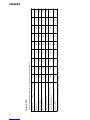
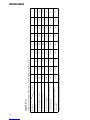
* If a steal chimney is used the measure will be 100mm
250 915 710 502 400 539 334 647 50
150 742 537 380 400 524 319 641 50
Med halvisolert skorstein /
With half insulated steel chimney
With side cover, plain
With decor glass sides
Basic model
Min. distance to combustible wall by different configurations, fig. 1a
Measure
Configuration
Jøtul F 370
Jøtul F 370 C (product with convection kit with
side glasses and half insulated chimney)
Jøtul F 377 (product with soap stone sides and top)

5
ENGLISH
205
221
452
442
4-4633-P11
1025
740
1150
410
66
181
max 90°
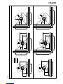
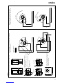
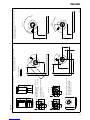
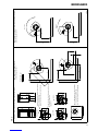
Distance to combustible wall with revolvable pedestal:
See table above.
b
a
c
d
e
f
h
g
i
max 180°
d
a
h
e
494 482
205
247
489
181
205
241
474
88
181
100
Hole in floor for outside air
Ø100mm connection
Jøtul F 371, F 374, F 375, F 376,
F 377, F 379
Min. measure floorplate
X/Y = Acc. to national standards
and regulations.
Combustible wall
X
Y
Fig. 1a
Min. distance to combustible wall:
See table above.
Product:
Jøtul F 371 / F 373 / F 374 / F 375 / F 376 / F 377 / F 379 / F 370 C
Hole in floor for outside air
Ø100mm connection
Jøtul F 373
Jøtul F 377:Jøtul F 370 C:
Base model:

6
ENGLISH
abcdefghi
100
100
643
643
438
438
310
310
200
200
492
492
287
287
421
421
40
40
jkl
mnopqr
550
550
480
380
440
340
735
735
799
669
773
659
934
934
999
884
962
841
st
756
556
1156
930
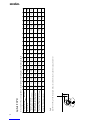
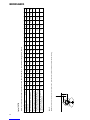
100 643 438 310 200 552 347 421 100 550 - - 795 - - 994 - - - -
* If a steal chimney is used the measure will be 100 mm
100 671 466 330 200 524 319 441 50 550 400 200 888 - 807 956 - 897 --
100 703 498 354 200 539 334 447 50 550 400 250 892 - 885 961 - 960 - -
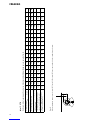
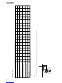
Min. distance to combustible wall protected by firewall in different configurations, fig. 1b
Measure
Configuration
Jøtul F 370
Jøtul F 372, F 375, F 376, F 379 with ext. air
through wall
With side cover plain
Basic model
Jøtul F 370 C (product with convection
kit andhalf insulated chimney)
Jøtul F 377 (product with soap stone
sides and top)
Fig. 1 c
Minimum distance to wall for Jøtul F 375, F 376 and F 379 with external air supply through wall
min 100
min 347


8
Requirements for protection of inflammable
floors in front of the fireplace
The front plate must comply with national laws and regulations.
Contact your local building authorities regarding restrictions and
installation requirements.
3.3 Walls
Distance from the wall of flammable material
The fireplace is authorised for use with an uninsulated flue with
the distances to the wall of flammable material as shown in fig 1.
3.4 Ceiling
There must be a minimum distance of 1000 mm to a combustible
ceiling above the fireplace.
4.0 Installation
N.B. Check that the fireplace is free of any damage prior to
commencing installation.
The product is heavy! Make sure you have assistance when
erecting and installing the fireplace.
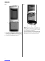
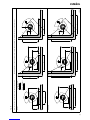
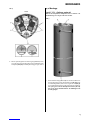
4.1 Prior to installation
1. Standard product supplied in two packages. One with the
fireplace itself and one with optional base in cast-iron/
concrete/glass or pedestal in cast-iron.
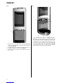
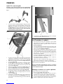
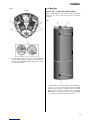
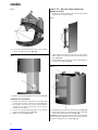
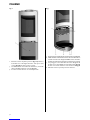
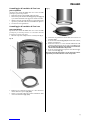
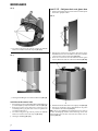
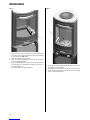
2. When the product is unpacked, the burn plates, baffle plate,
exhaust deflector, base plate, ash pan and riddling grate are
removed. Also remove the small side burn plates and gasket
for flue pipe which are in the ash pan.
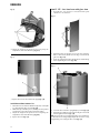
Fig. 3
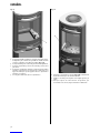
3. Lift off the top plate with the top grid (fig. 3 A) and bowl (fig. 3 B).
4. Check that the operating handles work.
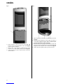
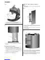
5. If the rear flue pipe outlet is used, first drill holes (fig. 5 A) in
the cut-out covers for the flue pipe before they are knocked
out with the aid of e.g a ball-pane hammer.
6. Place the wooden block (fig. 5 B) that holds the exhaust
deflectors in position so that the side plates are supported
when the cut-out covers are removed.
7. Spread out the cardboard packaging on the floor. Lay the
stove carefully on its side.
ENGLISH

9
ENGLISH
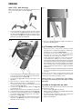
Fig. 4
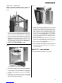
8. If the glass décor set (optional extras) is to be used, the 4
recessed head screws on the bottom are removed (fig. 4B)
with the aid of the key included with the glass décor set.
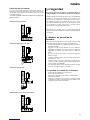
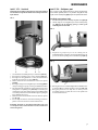
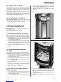
4.2 Assembly
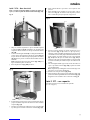
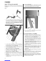
Jøtul F 371 - cast-iron base
N.B. If the flexible hose is to be connected through a hole in the
floor, the knock out covers are not knocked out/removed.
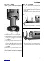
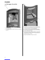
Fig. 5
1. If flexible hose, 100 mm diameter, for external air supply is
to be connected to the outlet under the burn chamber (fig. 4 C),
drill one hole (fig. 5 C) in each cut-out cover at the lower part
of the base and knock them out. N.B. Make sure the rear plate
(fig. 6 A) in the base is positioned, when the cut-out cover is
being knocked out.

10
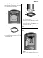
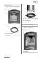
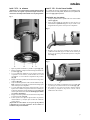
Fig. 6
2. Remove rack and rear plate in the base. Check that the handle
in the external air vent (fig. 4D) is in the foremost position.
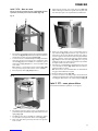
3. Assemble the base with the burn chamber with the aid of
the 4 screws (M8x30 mm) from the screws bag (fig. 4 A).
4. Get assistance and carefully lift the product up.
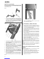
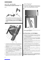
Fig. 7
5. Adjust the product with the help of the 4 adjusting screws
(fig. 7 C).
6. Draw the flexible hose through the hole and fasten it to the
outlet with the aid of a hose clip. N.B. Make sure that the
hose is long enough to avoid any joints.
7. The base area must be protected from heat radiation from
the product with the aid of the accompanying heat shield
(fig. 7 A). Fasten this with the 2 screws as shown in fig. 7 B.
8. Reassemble the the rack and the rear plate in the base.
ENGLISH

11
ENGLISH
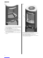
Jøtul F 373 - pedestal
Important! If the rotating set is to be assembled, this must be done
now before the pedestal is fastened to the hearth. See assembly
instructions which accompany the rotating set.
Fig. 11
1. Adjust the product with the help of the 3 adjusting screws
(fig. 11 A).
2. Assemble the pedestal to the hearth’s bottom plate with the
aid of the 4 screws from the bag of screws ( (fig. 4 A).
3. If the external air supply via the external air vent is to be used,
the flexible hose, 100 mm diameter, is connected to the vent
on the product (fig. 4 C) now.
4. Push the handle in the external air vent to the foremost
position (fig. 4 D).
5. Fasten the hose to the external air vent with the aid of a
hose clip. N.B. Make sure that the hose is long enough to
avoid any joints.
6. If the external air is to be supplied through the floor, place the
flexible gasket (fig. 11 B) around the hose, 100 mm diameter,
that is drawn through the hole in the floor. Note! The hole is
in the center of the pedestal/flue pipe.
7. Push the handle in the external air vent to the rear position
(fig. 4 E).
8. Get assistance and carefully lift the product up and place it
directly above the external air supply.
Important! Check that the handle in the external air vent is in
the foremost position if the external air is not to go through
the pedestal.
Jøtul F 374 - Cast iron leg
If external air supplied via the external air vent is to be used,
connect a flexible hose, Ø 100 mm, to the external air vent
(fig. 4 C) on the product.
Installation with external air
1. Push the lever on the external air vent to its forward position
(fig. 4 D).
2. Attach the hose to the external air vent using a hose clip.
NB! Make sure the hose is long enough to avoid any joints
being necessary.
Fig. 12
3. Move the cast iron leg towards the burn chamber as the
external air hose is passed through the leg and, if appropriate,
through the opening in its back (fig. 12).
Fig. 13
4. Attach the base to the burn chamber using the 4 screws (M8
x 30 mm) from the bag of screws (fig. 13 A).
5. With the help of another person, carefully raise the product
and position it correctly over the external air supply.

12
Fig. 14
6. Adjust the height of the product if necessary, using the
adjustment screws beneath the leg (fig. 14 A).
Fig. 15
7. Replace the cover for the external air supply (fig. 15 A).
Installation without external air
1. Attach the base to the burn chamber using the 4 screws (M8
x 30 mm) from the bag of screws (fig. 13A).
2. With the help of another person, carefully raise the product
and position it correctly over the external air supply.
3. Adjust the height of the product if necessary, using the
adjustment screws beneath the leg (fig. 14A).
4. Replace the cover (fig. 15 A).
Jøtul F 375 - Cast iron base with glass door
1. Assemble the cast iron base as described under point
“Jøtul F 371 - cast iron base”.
Fig. 16
2. Attach the hinge for the glass door to the base using the
M6 x 20 mm screws, which are in the bag of screws for the
glass door (fig. 16 A).
3. Insert the spring between the threaded holes and the hinge
before tightening the screws (fig. 16B).
Fig. 17
4. Screw the other end of the spring firmly in position (fig. 17 A).
5. Attach the door damper to the inside of the glass door in the
bottom right-hand corner (fig. 17 B).
NB! There must be an even gap between the door and the base
to allow the door to hang straight. Adjust the door if necessary,
by tightening or loosening the two screws (fig. 17 C).
ENGLISH

13
Jøtul F 376 – Glass base
NB! If connecting the flex hose through a hole in the floor, do not
knock out the removable cover plates (Fig. 18 A).
Fig. 18
1. Loosen the screws holding the upper glass clips on either
side (Figs. 18 B and C). Check that the lever on the external
air vent is in the forward position (Fig. 4D).
2. If connecting a flex hose (Ø 100 mm) for external air supply
to the external air vent/outlet (Fig. 4 C) beneath the burn
chamber, first drill a hole (Fig. 18 A) in the removable cover
plates before they are knocked out. NB! Leave the rear plate
in the base (Fig. 18 D) in place when the cover plates are
knocked out.
3. Remove the rear plate (Fig. 18 D) in the base.
Fig. 19
4. Place the base in the correct position on the floor plate (if
any). Level the product using the 4 adjustment screws (Fig. 19 A).
5. Attach the base to the burn chamber using the 4 screws
(M8 x 30 mm) from the bag of screws (Fig. 19 B).
6. Carefully raise the product with the help of another person.
7. Adjust the glass door, if necessary, with the screws as shown
in Fig. 17 C. There must be an even gap between the door and
the base to allow the door to hang straight.
Fig. 20
8. Install the side glass panels by positioning them in the lower
glass clips (Fig. 20 A). Lift up the upper clips and press them
down onto the side glass. Make sure there is an even gap
between the side glass and the side plate at both the front
and back. Tighten the front screw for the side glass (Fig. 18 B).
The back screw (Fig. 18 C) should be loosened just sufficiently
to allow the glass clip to be raised without removing the
screw (this makes it easier if replacing the glass later on).
9. Pull the flex hose (if any) through a hole in the floor or rear
of the base (Fig. 18 A) and attach it to the outlet using a hose
clip. NB! Make sure the hose is long enough to make it
unnecessary to have any joints.
10. Replace the rear plate (Fig. 18 D).
11. The base area must be protected from heat radiation from
the product with the aid of the accompanying heat shield
(fig. 7 A). Fasten this with the 2 screws as shown in fig. 7 B.
Jøtul F 377 - with soapstone
Se separate installation manual (cat. no. 10043560).
ENGLISH

14
Jøtul F 379 - with three legs
NB! If connecting the flex hose through a hole in the floor, do not
knock out the removable cover plates (fig. 21 A).
Fig. 21
1. If connecting a flex hose (Ø 100 mm) for external air supply
to the external air vent (fig. 4 C) beneath the burn chamber,
first drill a hole (fig. 21 A) in the removable cover plates before
they are knocked out. NB! Place the parts on a suitable surface
before the cover plates are knocked out.
Fig. 22
2. The accompanying heat shield (fig. 22 A) should be used to
protect the base from the heat radiating from the product.
Secure this first with a screw (fig. 22 B).
3. Secure the brace (fig. 22 C) loosely into place with a screw
(fig. 22 D).
4. Attach the base to the burn chamber using the 4 screws
(M8 x 30 mm) from the bag of screws (fig. 4 A).
5. Screw the legs together at the back edge using 2 screws that
are in the screw holes (fig. 22 E).
6. Secure the brace (fig. 22 C) into place with a screw (fig. 22 F)
and nut at both ends.
7. With the help of another person, carefully raise the product.
8. Level the product using the 4 adjustment screws (fig. 22 G).
9. If the legs are not properly aligned, loosen the screws (fig. 22 F)
on each side. Adjust the legs and tighten the screws again.
10. Tighten the screw (fig. 22 D).
11. Pull the flex hose through the hole and attach it to the outlet
using a hose clip. NB! Make sure the hose is long enough so
that joints are not necessary.
Fig. 23
12. Place the cover (fig. 23 A) into place. Make sure that the pin
(protrusion) B is facing down.
4.3 Chimneys and flue pipes
• The fireplace can be connected to a chimney and flue
pipe approved for solid fuel fired appliances with flue gas
temperatures specified in «2.0 Technical data”.
• The chimney’s cross-section must be at least as big as the
flue pipe’s cross-section. See «2.0 Technical data» when
calculating the correct chimney cross-section.
• Several solid fuel fired appliances can be connected to the
same chimney if the chimney’s cross-section is sufficient.
• Connection to the chimney must be carried out in accordance with
the installation instructions from the supplier of the chimney.
• Before making a hole in the chimney the fireplace should be
test-mounted in order to correctly mark the position of the
fireplace and the hole in the chimney. See fig. 1 for minimum
dimensions.
• Ensure that the flue pipe is inclined all the way up to the chimney.
• Use a flue pipe bend with a sweeping hatch that allows it to
be swept.
Be aware of the fact that it is particularly important that
connections have a certain flexibility in order to prevent
movement in the installation leading to cracks.
Chimney draught; See «2.0 Technical data». If the draught is
too strong you can install and operate a flue damper to control
the draught.
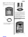
Assembly of flue pipe with top outlet
The product is supplied from the factory with the smoke outlet
mounted for top outlet.
1. Put the top plate (fig. 3 C) on the product.
2. Obtain assistance in lifting the top grate (fig. 3 A) and holding
it up while the flue is fastened.
3. Thread the flue pipe through the grate of the top plate and
place it on the smoke outlet of the top outlet.
4. Tighten well with gasket.
ENGLISH

15
Assembly of flue pipe with rear outlet
The product is supplied from the factory with the smoke outlet
mounted for top outlet. If you want a rear outlet, do the following:
1. Place the product in correct position (fig. 1).
Fig. 24
2. When changing to rear outlet, the smoke outlet (fig. 24 B) is
unscrewed from the top outlet.
3. Unscrew the cover for the rear outlet from the inside of the
burn chamber (fig. 24 A).
Fig. 25
4. Place the gasket on the end of the flue pipe (fig. 25 A).
5. Mount the smoke outlet (fig. 25 B) on the end of the flue pipe
that is fitted with the gasket.
6. Mount the flue pipe and smoke outlet from the inside of the burn
chamber and attach the smoke outlet using M8x30 mm screws.
N.B. If the flue pipe is longer than 350 mm it has to be assembled
into the smoke outlet from the outside of the product.
7. Fasten the cover to the top outlet (fig. 24) with the screws
that fastened the smoke outlet.
N.B. It is important that the joints/flue pipes are completely
sealed. Air leaks can prevent the flue pipe from functioning
properly.
4.4 Mounting of the product
Fig. 26
1. Place the baffle plate with the bar in the groove on the ribs
(fig. 26 A).
2. Move the base plate through the opening and place it on
the bottom.
ENGLISH

16
Fig. 27
3. Place the riddling grate in position on the base plate. Check
that the riddling grate’s slot on the right side is entered into
the riddling bar (fig. 27 A).
4. Place the ash pan at the bottom of the product.
5. Place the rear burn plate in the base plate’s rear groove.
6. Place the side burn plates on each side in the base plate’s side
grooves. Move the baffle plate in and place it so that it rests
on the side and rear burn plates.
7. Hold the baffle plate while the other side burn plate is
mounted.
Fig 28
8. Let the baffle plate rest on the burn plates.
9. Place the small side burn plates (fig. 28 A) in the base plate’s
groove under the side glasses.
10. Replace the top plate with the top grid and bowl.
11. Place the product data plate which is in the ash pan,
underneath the burn chamber.
ENGLISH

17
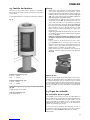
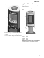
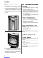
4.5 Control of functions
When the product is set up, always check the control functions.
These shall move easily and function satisfactorily.
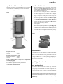
Jøtul F 370 is equipped with the following controls:
Fig. 29
Air vent fig. 29 A
Pushed in: Closed
Pulled out: Open
Ignition vent, fig. 29 B
Pushed in: Closed
Pulled out: Open
Riddling grate (same handle as for the ignition vent) (Fig. 29 B)
Right handle is pushed in and out.
Handle for door fig. 29 C:
Is opened by pulling handle out.
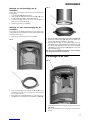
4.6 Use
• Open the air vent and the ignition vent by pulling it out all
the way (fig. 29 A & B). If necessary, keep the door slightly
open. (Use a glove, for example, as the handle can become hot.)
• Place two medium sized logs in/out on each side of the base.
N.B. In order to avoid sooting on the glass, it is important that
the log is not placed adjacent to the glass on the product.
• Crumple some newspaper (or birch bark) between these and
add some kindling wood in a criss-cross pattern on top and
light the newspaper. (Fig. 30)
• Gradually increase the size of the fire, but the wood should
not be stacked higher than the horizontal holes on the back
burn plate. See fig. 29 H.
• Finally, place a medium-sized log on the top of the pile.
• Place 2 or 3 briquettes or kindling sticks under the top layer
of kindling and light the fire.
• NB: The maximum height of the pile of the wood should
be just below the horizontal holes. The holes must not be
covered.
• Close the ignition vent (fig. 29 B) when the firewood has
ignited and the fire is burning well.
• Check that the afterburning (secondary combustion) starts. This
is best indicated by yellow, flickering flames under the baffle.
• Then regulate the rate of combustion to the desired level of
heating by adjusting the air vent (fig. 29 A).
Fig. 30
Adding firewood
Stoke the stove frequently but only add small amounts of fuel at
a time. If the stove is filled too full, the heat created may cause
extreme stress in the chimney. Add fuel to the fire in moderation.
Avoid smouldering fires as this produces the most pollution.
The fire is best when it is burning well and the smoke from the
chimney is almost invisible.
4.7 Danger of overheating
The fireplace must never be used in a manner that
causes overheating
Overheating occurs when there is too much fuel and/or too much
air so that too much heat develops. A sure sign of overheating is
when parts of the fireplace glow red. If this happens, reduce the
air vent opening immediately.
Seek professional advice if you suspect that the chimney is not
drawing properly (too much/too little draught). For further
information, see «4.0 Installation» (Chimney and flue pipe).
ENGLISH

18
4.8 Ash removal
Jøtul F 370 has an ash pan which makes it easy to remove the ashes.
1. Only remove ashes when the fireplace is cold.
2. Push/pull the handle for the ash grate/ignition vent out and
in several times so that the ashes fall down into the ash pan.
Use something like a glove to grab the handle on the ash pan.
3. Make sure that the ash pan doesn’t fill up so high that it keeps
ash from coming through the grate into the pan.
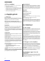
5.0 Daily use
Odours when using the fireplace for the first time
When the fireplace is used for the first time, it may emit an
irritating gas which may smell slightly. This happens because
the paint dries.The gas is not toxic but the room should be
thoroughly ventilated. Let the fire burn with a high draught until
all traces of the gas have disappeared and no smoke or odours
can be detected.
Heating advice
NB: Logs that have been stored outdoors or in a cold room should
be brought indoors 24 hours before use to bring them up to room
temperature.
There are various ways of heating the stove but it is always
important to be careful about what you put in the stove. See the
section on “Wood quality”.
Wood quality
By quality wood we mean most well-known types of wood such
as birch, spruce and pine.
The logs should be dried so that the moisture content is no more
than 20%.
To achieve this, the logs should be cut during the late winter. They
should be split and stacked in a way that ensures good ventilation.
The wood stacks should be covered to protect the logs from rain.
The logs should be brought indoors during early autumn and
stacked/stored for use in the coming winter.
Be especially careful never to use the following materials as fuel
in your fireplace:
• Household rubbish, plastic bags, etc.
• Painted or impregnated timber (which is extremely toxic).
• Laminated wooden planks.
• Driftwood
These may harm the product and are also pollutants.
NB: Never use petrol, paraffin, methylated spirit or similar liquids
to light the fire. You may cause serious injury to yourself and
damage to the product.
Wood consumption
Jøtul F 370 has a nominal heat output of 5,5 kW. Use of
wood, with nominal heat emission: Approx. 1,9 kg/h. Another
important factor for proper fuel consumption is that the
logs are the correct size. The size of the logs should be:
Kindling:
Length: 30 cm
Diameter: 2-5 cm
Amount per fire: 6-8 pieces
Firewood (split logs):
Length: Ca 20 - 30 cm
Diameter: Approx. 8 cm
Intervals for adding wood: Approximately every 45 minutes
Size of the fire: 1.4 kg
Amount per load: 2 pieces
Nominal heat emission is achieved when the air vent (fig. 29 A)
is open approximately 100% and the handle for the ignition vent
pulled out approximately 1-2 cm (fig. 29 B).
6.0 Maintenance
6.1 Cleaning the glass
The product is equipped with an air wash for the glass. Air is
sucked in through the air vent on the top of the product and
down along the inside of the glass.
However, some soot will always stick to the glass, but the quantity
will depend on the local draught conditions and adjustment of
the air vent. Most of the soot layer will normally be burned off
when the air vent is opened all the way and a fire is burning
briskly in the fireplace.
Good advice! For normal cleaning, moisten a paper towel with
warm water and add some ash from the burn chamber. Rub it over
the glass and then clean the glass with clean water. Dry well. If it
is necessary to clean the glass more thoroughly we recommend
using a glass cleaner (follow the instructions on the bottle).
6.2 Cleaning and soot removal
Soot deposits may build up on the internal surfaces of the
fireplace during use. Soot is a good insulator and will therefore
reduce the fireplace’s heat output. If soot deposits accumulate
when using the product, they can be easily removed by using a
soot remover.
In order to prevent a water and tar layer from forming in the
fireplace you should regularly allow the fire to burn hot in order
to remove the layer. An annual internal cleaning is necessary to
get the best heating effect from the product. It is a good idea
to do this in connection with the sweeping of the chimney and
flue pipes.
6.3 Sweeping of flue pipes to the chimney
On certain free-standing fireplaces the top plate can be lifted off
and the pipe swept through the top.
Otherwise, flue pipes must be swept through the flue pipe
sweeping hatch or through the product’s door opening. Then,
the baffle must be removed.
ENGLISH

19
6.4 Inspection of the fireplace
Jøtul recommends that you personally inspect your fireplace
carefully after sweeping/cleaning. Check all visible surfaces for
cracks. Also check that all joints are sealed and that the gaskets
are in the correct position. Any gaskets showing signs of wear or
deformation must be replaced.
Thoroughly clean the gasket grooves, apply ceramic glue
(available from your local Jøtul dealer), and press the gasket well
into place. The joint will dry quickly.
6.5 Exterior maintenance
Painted products may change colour after several years usage. The
surface should be cleaned and brushed free of any loose particles
before new paint is applied.
7.0 Service
Warning! Any unauthorised change to the product is illegal.
Only use original spare parts.
7.1 Replacing the baffle/exhaust
deflector
(N.B. If you use tools, be aware that the vermiculite plates may
be damaged by rough treatment).
1. Lift up the front edge of the baffle plate and tilt it out
(fig. 29 G). Remove the side burn plates (fig. 29 F) and the
rear burn plate (fig. 29 E).
2. The exhaust deflector, in cast-iron - that is located above the
baffle plate, rests with the bar on the ribs at the rear flue
outlet (fig. 26 A). Lift the exhaust deflector slightly up, pull it
forward and tilt it out.
3. For reassembly follow the same procedure for installation,
but in reverse.
7.2 Replacement of burn plates/base
plate
(N.B. If you use tools, be aware that the vermiculite plates may
be damaged by rough treatment).
1. Lift up the front edge of the baffle plate and tilt it out. Remove
the side burn plates (fig. 29 F) and the rear burn plate (fig. 29 E).
2. Then lift up the grate and the base plate and take it out (fig.
29 D).
3. Follow the same procedure for installation, but in the opposite
sequence.
4. When reassembling the grate and the base plate, make sure
that the riddling bar (fig. 27 A) that moves the riddling grate
is threaded into the slot on the right edge of the grate.
7.3 Replacing the inner/outer side
glass
1. Lift up the front edge of the baffle plate and tilt it out Remove
the side burn plates (fig. 29 F) and the rear burn plate (fig. 29 E).
2. The exhaust deflector, in cast-iron - that is located above the
baffle plate, rests with the bar on the ribs at the rear flue
outlet (fig. 26 A). Lift the exhaust deflector slightly up, pull it
forward and tilt it out.
3. Remove riddling grate, base plate and ash pan (fig. 29 D).
Fig. 31
Fig. 32
4. Unscrew the upper and lower screws (fig. 31 A and 32 A), and
tilt the glass holder with the glass carefully out through the
door. N.B. The glass holder also keeps the outer glass in place
5. Remove the glass and possibly replace gaskets. If needed
replace the external glass.
6. For reassembly follow the same procedure for installation,
but in reverse.
ENGLISH

20
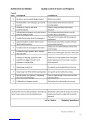
8.0 Operational problems -
troubleshooting
Poor draught
1. Check the length of the chimney and that it complies with
national laws and regulations. (See also «2.0 Technical
data» and «4.0 Installation» (Chimney and flue pipe) in the
installation manual for information.)
2. Make sure that the minimum cross section on the chimney is
according to «2.0 Technical data» in the installation manual.
3. Make sure that there is not anything preventing the smoke
gasses from escaping: branches, trees, etc.
4. Upon suspicion of excessive/poor draught in the chimney,
seek professional help for measurement and adjustment.
The fire extinguishes after a while
1. Make sure that the firewood is sufficiently dry.
2. Find out whether there is negative pressure in the house, close
mechanical fans and open a window close to the fireplace.
3. Check that the air vent is open.
4. Check that the flue outlet is not clogged by soot.
Unusual amount of soot accumulates on the
glass
Some soot will always stick to the glass, but the quantity depends
on:
1. Moisture in the fuel.
2. The local draught conditions.
3. Air vent opening.
Most of the soot will normally burn off when the air vent is
opened all the way and a fire is burning briskly in the fireplace.
(See «6.1 Cleaning the glass».)
9.0 Optional equipment
9.1 Decoration plates
Decoration plates, cover for side windows (2 units), black paint -
cat. no. 50037271 (350990).
Decoration plates, cover for side windows (2 units), grey paint -
cat. no. 50037272 (350991).
Soapstone, top 25 mm one-piece - cat. no. 50012988 (350992).
Soapstone, top 25 mm three-piece - cat. no. 50013013 (361011)
(substitute for 50012988 (350992) installed with steel chimney).
9.2 Glass decoration, top, sides and front
(see separate installation manual)
Glass set for rear smoke outlet, black paint,
- cat. no. 51012250 (350993)
Glass set for rear smoke outlet, grey paint,
- cat. no. 51012251 (350994)
Glass set for top smoke outlet, black paint,
- cat. no. 51012252 (350995)
Glass set for top smoke outlet, grey paint,
- cat. no. 51012253 (350996)
9.3 Rotating kit
(See separate installation manual)
Rotating set for Jøtul F 373, - cat. no. 51012254 (350997)
9.4 Wood store
Black paint - cat. no. 50012995 (351160)
Grey paint - cat. no. 50013037 (351161)
9.5 Cast iron door for base (Jøtul F 371)
Black paint - cat. no. 51036917 (351115)
Grey paint - cat. no. 51036918 (351116)
9.6 High Top
Cat. no. 51012304
9.7 Heat storage system
Cat. no. 10026701
9.8 Soapstone
Jøtul F 377 soapstone kit, cat. no. 21043545
Jøtul F 377 HT soapstone kit, cat. no. 21043546
9.9 Convection kit
Jøtul F 370 C convection, sides, BP, cat. no. 50043647
Jøtul F 370 C, convection, top, BP, cat. no. 50043642
ENGLISH
La pagina si sta caricando...
La pagina si sta caricando...
La pagina si sta caricando...
La pagina si sta caricando...
La pagina si sta caricando...
La pagina si sta caricando...
La pagina si sta caricando...
La pagina si sta caricando...
La pagina si sta caricando...
La pagina si sta caricando...
La pagina si sta caricando...
La pagina si sta caricando...
La pagina si sta caricando...
La pagina si sta caricando...
La pagina si sta caricando...
La pagina si sta caricando...
La pagina si sta caricando...
La pagina si sta caricando...
La pagina si sta caricando...
La pagina si sta caricando...
La pagina si sta caricando...
La pagina si sta caricando...
La pagina si sta caricando...
La pagina si sta caricando...
La pagina si sta caricando...
La pagina si sta caricando...
La pagina si sta caricando...
La pagina si sta caricando...
La pagina si sta caricando...
La pagina si sta caricando...
La pagina si sta caricando...
La pagina si sta caricando...
La pagina si sta caricando...
La pagina si sta caricando...
La pagina si sta caricando...
La pagina si sta caricando...
La pagina si sta caricando...
La pagina si sta caricando...
La pagina si sta caricando...
La pagina si sta caricando...
La pagina si sta caricando...
La pagina si sta caricando...
La pagina si sta caricando...
La pagina si sta caricando...
La pagina si sta caricando...
La pagina si sta caricando...
La pagina si sta caricando...
La pagina si sta caricando...
La pagina si sta caricando...
La pagina si sta caricando...
La pagina si sta caricando...
La pagina si sta caricando...
La pagina si sta caricando...
La pagina si sta caricando...
La pagina si sta caricando...
La pagina si sta caricando...
La pagina si sta caricando...
La pagina si sta caricando...
La pagina si sta caricando...
La pagina si sta caricando...
La pagina si sta caricando...
La pagina si sta caricando...
La pagina si sta caricando...
La pagina si sta caricando...
La pagina si sta caricando...
La pagina si sta caricando...
La pagina si sta caricando...
La pagina si sta caricando...
La pagina si sta caricando...
La pagina si sta caricando...
La pagina si sta caricando...
La pagina si sta caricando...
La pagina si sta caricando...
La pagina si sta caricando...
La pagina si sta caricando...
La pagina si sta caricando...
La pagina si sta caricando...
La pagina si sta caricando...
La pagina si sta caricando...
La pagina si sta caricando...
La pagina si sta caricando...
La pagina si sta caricando...
La pagina si sta caricando...
La pagina si sta caricando...
-
 1
1
-
 2
2
-
 3
3
-
 4
4
-
 5
5
-
 6
6
-
 7
7
-
 8
8
-
 9
9
-
 10
10
-
 11
11
-
 12
12
-
 13
13
-
 14
14
-
 15
15
-
 16
16
-
 17
17
-
 18
18
-
 19
19
-
 20
20
-
 21
21
-
 22
22
-
 23
23
-
 24
24
-
 25
25
-
 26
26
-
 27
27
-
 28
28
-
 29
29
-
 30
30
-
 31
31
-
 32
32
-
 33
33
-
 34
34
-
 35
35
-
 36
36
-
 37
37
-
 38
38
-
 39
39
-
 40
40
-
 41
41
-
 42
42
-
 43
43
-
 44
44
-
 45
45
-
 46
46
-
 47
47
-
 48
48
-
 49
49
-
 50
50
-
 51
51
-
 52
52
-
 53
53
-
 54
54
-
 55
55
-
 56
56
-
 57
57
-
 58
58
-
 59
59
-
 60
60
-
 61
61
-
 62
62
-
 63
63
-
 64
64
-
 65
65
-
 66
66
-
 67
67
-
 68
68
-
 69
69
-
 70
70
-
 71
71
-
 72
72
-
 73
73
-
 74
74
-
 75
75
-
 76
76
-
 77
77
-
 78
78
-
 79
79
-
 80
80
-
 81
81
-
 82
82
-
 83
83
-
 84
84
-
 85
85
-
 86
86
-
 87
87
-
 88
88
-
 89
89
-
 90
90
-
 91
91
-
 92
92
-
 93
93
-
 94
94
-
 95
95
-
 96
96
-
 97
97
-
 98
98
-
 99
99
-
 100
100
-
 101
101
-
 102
102
-
 103
103
-
 104
104


Jotul F 371 Manuale del proprietario
- Categoria
- Camini
- Tipo
- Manuale del proprietario
in altre lingue
- English: Jotul F 371 Owner's manual
- français: Jotul F 371 Le manuel du propriétaire
- español: Jotul F 371 El manual del propietario
- Nederlands: Jotul F 371 de handleiding
Documenti correlati
Altri documenti
-
Jøtul F 475 Installation And Operating Istructions
-
-
-
-
-
-
SEVERIN ZB 8182 SEVO Istruzioni per l'uso
-
STUV 16-H Guida d'installazione