
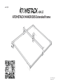
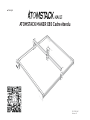
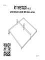
ATOMSTACK MAKER E85 Extended frame
English
F03-0105-0AA1
Versions: B

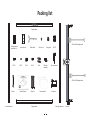
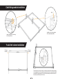
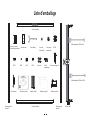
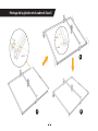
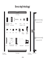
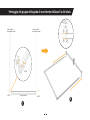
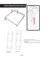
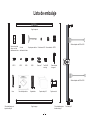
Packing list
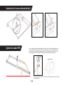
1
Dovetail groove
laser slide rail
M5*14 M5*8 M5*6 M4*8 T-Nut M3 screw
assembly Hex screwdriver
Y-axis left slide rail Suppo beam
Suppo beam
Y-axis right slide rail X-axis rail
Wrench Cable tie Foot bracket*3 Control box
Laser slide rail Cable holder M5 lock nut Timing belt M5*25
Product Manual
5PIN to 4PIN adapter cable
5PIN to 3PIN adapter cable

Suppo beam
Y-axis left slide rail Y-axis right slide rail
M5*25 M5*25
M5*25
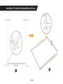
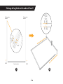
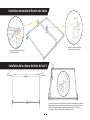
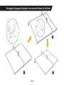
2
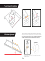
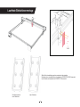
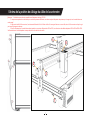
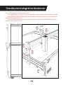
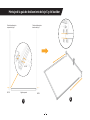
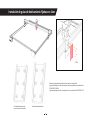
Assembly of X-axis slide rail assembly and frame
12

M5*25
M5*14
M5*6
3
3 5
4
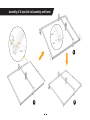
Assembly of X-axis slide rail assembly and frame

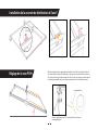
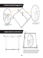
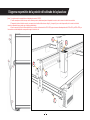
Fastening method of connecting
wire xing steel wire
Installation of the xing bracket
for the motherboard cable
4
M5*8
M3 screw
assembly
M3 screw
assembly
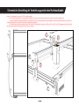
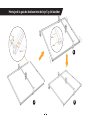
The stroke of the X-axis is too large. In order to prevent the left-right asymmet
in the assembly of the Y-axis synchronous belt, when the Y-axis synchronous belt
is assembled and tightened, the X-axis slide rail assembly should be close to the
limit columns at both ends of the Y-axis.
Y-axis limit column installation
Cable xing module installation

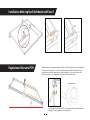
5
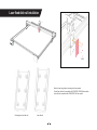
Y-axis timing belt installation
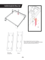
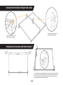
Judgment and adjustment method of the tightness of the POB wheel on the X-axis slide rail:
In the case of ensuring that the suppo does not shake, one end of the machine can be lifted
to 45° from the horizontal plane, and then the X-axis or Y-axis suppo can be released from a
high place. If the bracket slides all the way at a constant speed, then it's tight enough.
POM wheel adjustment
The adjustment state of the POM wheel is from loose to tight cycle, just adjust to
the appropriate tightness.
90°
45°
M5*6

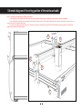
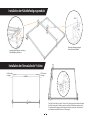
Dovetail groove laser slide rail Laser slide rail
Select the laser xing slide rail according to the laser module
Dovetail laser slide rail is compatible with ATOMSTACK 20W/30W laser module
Laser slide rail is compatible with ATOMSTACK 10W laser module
6
M4*8
Laser xed slide rail installation

Schematic diagram of the wiring position of the mainboard cable
1
2
3
45
7
Note: 1. The control box is compatible with 12V/24V power adapter.
2. When replacing the laser module with dierent power, you need to replace the suppoing power adapter, otherwise the laser module will be damaged!
3. After installing the connecting wire, it is necessa to tie the wire to the steel wire of the X-axis and the xed bracket with a cable tie, otherwise the connecting wire is too
long and may scratch the engraved object below.
4.For users whose existing laser module has a 4PIN or 3PIN power connector, we provide 5PIN to 4PIN and 5PIN to 3PIN adapter cables, please select the corresponding
adapter cable according to the actual situation.
*

8
Customer seice:
For detailed warranty policy, please visit our ocial website: www.atomstack.com
For technical suppo and seice, please email suppo@atomstack.com
Manufacturer:
Shenzhen AtomStack Technologies Co.,Ltd
Address:
17th Floor, Building 3A, Phase II, Intelligent Park, No. 76, Baohe Avenue,
Baolong Street, Longgang District, Shenzhen, Guangdong, China
Zip code: 518172
Scan QR code:
QR code reader/barcode scanner or any app with a scanner

ATOMSTACK MAKER E85 Erweiteer Rahmen
Deutsch
F03-0105-0AA1
Versions: B

Packliste
1
Schwalbenschwanz-Nut
Laser-Gleitschiene
M5*14 M5*8 M5*6 M4*8 T-Mutter M3-Schraube
Montage Sechskantschraubendreher
Y-Achse linke
Gleitschiene
Stützbalken
Suppo beam
Y-Achse rechte
Gleitschiene
Schiene X-Achse
Schraubenschlüssel Kabelbinder Fußhalterung*3 Schaltkasten
Laser-Gleitschiene Kabelhalter Kontermutter M5 Zahnriemen M5*25
Produkthandbuch
5PIN auf 4PIN Adapterkabel
5PIN auf 3PIN Adapterkabel

Stützbalken
Y-Achse linke
Gleitschiene
Y-Achse rechte
Gleitschiene
M5*25 M5*25
M5*25
2
Montage der X-Achsen-Gleitschieneneinheit und des Rahmens
12

M5*25
M5*14
M5*6
3
3 5
4
Montage der X-Achsen-Gleitschieneneinheit und des Rahmens

Befestigungsmethode der Verbindung
Drahtbefestigung Stahldraht
Einbau des Befestigungsbügels
für das Motherboardkabel
4
M5*8
M3-Schraube
Montage
M3-Schraube
Montage
Der Hub der X-Achse ist zu groß. Um eine Links-Rechts-Asymmetrie bei der Montage
des Zahnriemens der Y-Achse zu vermeiden, sollte die Gleitschienenanordnung der
X-Achse bei der Montage und beim Spannen des Zahnriemens der Y-Achse nahe an
den Endsäulen an beiden Enden der Y-Achse liegen.
Installation der Grenzsäule der Y-Achse
Installation der Kabelbefestigungsmodule

5
Einbau des Zahnriemens der Y-Achse
Beueilungs- und Einstellveahren für den festen Sitz des POB-Rades auf der X-Achsen-Gleitschiene:
Um sicherzustellen, dass die Halterung nicht wackelt, kann ein Ende der Maschine bis zu 45° aus der
horizontalen Ebene angehoben werden, und dann kann die X-Achsen- oder Y-Achsen-Halterung von
einem hohen Punkt aus gelöst werden. Wenn die Halterung mit konstanter Geschwindigkeit bis zum
Anschlag gleitet, ist sie fest genug.
POM-Radeinstellung
Der Einstellzustand des POM-Rades reicht von locker bis fest, stellen Sie einfach die
die entsprechende Festigkeit ein.
90°
45°
M5*6

Schwalbenschwanznut
Laser-Gleitschiene
Laser-Gleitschiene
Wählen Sie die Laserbefestigungsschiene entsprechend dem jeweiligen
Schwalbenschwanz-Lasergleitschiene ist kompatibel mit ATOMSTACK 20W/30W Lasermodul
Laser-Gleitschiene ist kompatibel mit ATOMSTACK 10W Lasermodul
6
M4*8
Laseeste Gleitschienenmontage

Schematische Darstellung der Verdrahtungsposition des Mainboardkabels
1
2
3
45
7
Hinweis: 1. das Steuergerät ist mit einem 12V/24V-Netzteil kompatibel
2. Wenn Sie das Lasermodul durch ein anderes Netzteil ersetzen, müssen Sie auch das Netzteil austauschen, da sonst das Lasermodul beschädigt wird!
3. Nach der Installation des Verbindungsdrahtes ist es notwendig, den Draht mit einem Kabelbinder an den Stahldraht der X-Achse und die feste Halterung zu binden, sonst
ist der Verbindungsdraht zu lang und kann das graviee Objekt darunter zerkratzen.
4.Für Benutzer, deren vorhandenes Lasermodul einen 4PIN- oder 3PIN-Stromanschluss hat, bieten wir 5PIN-auf-4PIN- und 5PIN-auf-3PIN-Adapterkabel an. Bitte wählen Sie
das entsprechende Adapterkabel entsprechend der tatsächlichen Situation.
*

8
Kundenseice:
Ausführliche Informationen zur Garantie nden Sie auf unserer oziellen
Website: www.atomstack.com
Für technische Unterstützung und Seice, senden Sie bitte eine
E-Mail an suppo@atomstack.com
Hersteller:
Shenzhen AtomStack Technologies Co.,Ltd
Adresse:
17. Stock, Gebäude 3A, Phase II, Intelligent Park, Nr. 76, Baohe Avenue,
Baolong Street, Bezirk Longgang, Shenzhen, Guangdong, China
Postleitzahl: 518172
QR-Code scannen:
QR-Code-Leser/Barcode-Scanner oder eine beliebige App mit einem Scanner

ATOMSTACK MAKER E85 Cadre étendu
Français
F03-0105-0AA1
Versions: B

Liste d'emballage
1
Rainure en queue
d'aronde glissière laser
M5*14 M5*8 M5*6 M4*8 Ecrou en T Vis M3
assemblage Tournevis hexagonal
Glissière gauche
de l'axe Y
Poutre de soutien
Poutre de soutien
Glissière droite
de l'axe Y
Rail de l'axe X
Clé à molette Attache-câbles Suppo de pied*3 boîte de contrôle
Glissière laser Poe-câbles Écrou de
blocage M5
Courroie de
distribution
M5*25
Manuel du produit
Câble adaptateur 5PIN à 4PIN
Câble adaptateur 5PIN vers 3PIN
La pagina si sta caricando...
La pagina si sta caricando...
La pagina si sta caricando...
La pagina si sta caricando...
La pagina si sta caricando...
La pagina si sta caricando...
La pagina si sta caricando...
La pagina si sta caricando...
La pagina si sta caricando...
La pagina si sta caricando...
La pagina si sta caricando...
La pagina si sta caricando...
La pagina si sta caricando...
La pagina si sta caricando...
La pagina si sta caricando...
La pagina si sta caricando...
La pagina si sta caricando...
La pagina si sta caricando...
La pagina si sta caricando...
La pagina si sta caricando...
La pagina si sta caricando...
La pagina si sta caricando...
La pagina si sta caricando...
La pagina si sta caricando...
La pagina si sta caricando...
-
 1
1
-
 2
2
-
 3
3
-
 4
4
-
 5
5
-
 6
6
-
 7
7
-
 8
8
-
 9
9
-
 10
10
-
 11
11
-
 12
12
-
 13
13
-
 14
14
-
 15
15
-
 16
16
-
 17
17
-
 18
18
-
 19
19
-
 20
20
-
 21
21
-
 22
22
-
 23
23
-
 24
24
-
 25
25
-
 26
26
-
 27
27
-
 28
28
-
 29
29
-
 30
30
-
 31
31
-
 32
32
-
 33
33
-
 34
34
-
 35
35
-
 36
36
-
 37
37
-
 38
38
-
 39
39
-
 40
40
-
 41
41
-
 42
42
-
 43
43
-
 44
44
-
 45
45


in altre lingue
- français: ATOMSTACK E85 Manuel utilisateur
- español: ATOMSTACK E85 Manual de usuario
- Deutsch: ATOMSTACK E85 Benutzerhandbuch