
BBV27900 11/2019 1/88
ENGLISH
INSTRUCTION SHEET
for HMISTO5pp and HMISTUp55/p55W
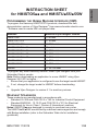
PROGRAMMING THE HUMAN MACHINE INTERFACE (HMI)
To program the Harmony HMISTO/STU products, download the free,
demonstration version of Vijeo Designer1 from www.schneider-electric.com:
1 Software used to create HMI unit project data.
To program any other Harmony devices, order Vijeo Designer from your
Schneider Electric vendor.
Note: Before downloading an application to a new HMIS5T using Vijeo
Designer V6.0 SP3 or higher :
• Ensure that your application is configured to use the target model HMIS5T.
If not, change the target model to HMIS5T before downloading.
Or
• Upgrade Vijeo Designer to version 6.1 to avoid any misuse.
RELEVANT STANDARDS
These products are manufactured in accordance with:
• Standard UL 508 and CSA C22.2 n°142 for Industrial Control Equipment
• Standard ANSI/ISA - 12.12.01 and CSA C22.2 n°213 for Electrical
Equipment for Use in Class I, Division 2 Hazardous Locations
Notes: HMISTO5pp are designed to comply to merchant navy rules.
The HMISTUp55/p55W are certified by merchant marine agencies and comply
with Bridge installation (refer to the Schneider Web site for installation
guidelines).
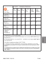
Modules Minimum Vijeo Designer Version
HMISTO501 6.0 or later
HMISTO511/512 5.1 or later
HMISTO531/532 6.0 SP1 or later
HMISTU655 PV 04 5.1 or later
HMISTU655 PV 04 6.1 SP1 or later
HMISTU855 PV 03 5.1 SP2 or later
HMISTU855 PV 03 6.1 SP1 or later
HMISTU655W 6.1 SP1 or later
HMISTU855W 6.1 SP1 or later
HMIS5T 6.1 SP1 or later

2/88 BBV27900 11/2019
ENGLISH
The HMISTO5pp and HMISTUp55/p55W must be installed, used and
maintained in accordance with:
• Standard WEEE, Directive 2002/96/EC
• Standard RoHS, Directive 2011/65/EU
• Standard RoHS China, Standard SJ/T 11364-2014
HMIZSUKIT
The Accessory Kit for the HMISTUp55/p55W contains:
• USB standard Type A cable holder
• USB Mini-B holder
• Anti-rotation Tee
• Panel adaptor
INSTALLATION PREREQUISITES
For use in Pollution Degree 2 environments.
For use on a flat surface of a Type 13 and/or Type 4X (Indoor Use Only)
Enclosure.

BBV27900 11/2019 3/88
ENGLISH
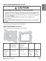
HMISTUp55/p55W INSTALLATION
This caution is not covered by UL certification.
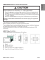
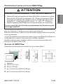
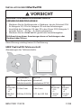
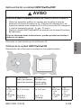
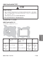
HMISTUp55/p55W CUT-OUTS
Cut-out dimensions for mounting on a flat surface:
CAUTION
ENVIRONMENTAL HAZARDS TO THE EQUIPMENT
• Mount the device in enclosure that meet the IP54 level of protection for
category 3G, IP6x for category 3D and the requirements relating to the
3G or 3D categories in Zones 2/22 (Category 3: normal level of protection
- G: Gas - D: Dust).
• Mount the HMISTUp55/p55W according to the manufacturer's
specifications.
Failure to follow these instructions can result in injury or equipment
damage.
A B (Steel sheet,
for example,
cabinet door)
B (Glass fiber
reinforced
plastics,
minimum GF30)
CD
+0
22.50 mm
-0.30
+0
0.88 in.
-0.01
1.5 to 6 mm
0.06 to 0.23 in.
3 to 6 mm
0.11 to 0.23 in.
+0
30.00 mm
-0.20
+0
1.18 in.
-0.007
+0
4.00 mm
-0.20
+0
0.15 in.
-0.007

4/88 BBV27900 11/2019
ENGLISH
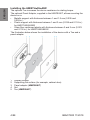
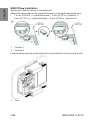
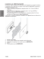
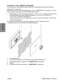
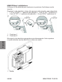
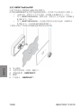
Installing the HMISTUp55/p55W
The optional Tee increases the device resistance to rotating torque.
The optional Panel Adaptor, supplied in the HMIZSUKIT, allows mounting the
device on a:
• Metallic support with thickness between 1 and 1.5 mm (0.039 and
0.059 in.)
• Plastic support with thickness between 1 and 3 mm (0.039 and 0.118 in.)
for HMISTU655/655W
• Glass fiber reinforced plastic with thickness between 2 and 3 mm (0.078
and 0.118 in.) for HMISTU855/855W
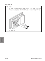
The illustration below shows the installation of the device with a Tee and a
panel adaptor:
1 Display module
2 Supporting flat surface (for example, cabinet door)
3 Panel adaptor (HMIZSUKIT)
4 Nut
5 Tee (HMIZSUKIT)

BBV27900 11/2019 5/88
ENGLISH
HMISTO5pp INSTALLATION PROCEDURES
This caution is not covered by UL certification.
Before installing the device, read the instructions below.
The installation gasket and installation fasteners (screw installation fasteners
or spring clips) are required for installing the device.
Mount the terminal in a clean, dry, robust and controlled enclosure (IP65
enclosure).
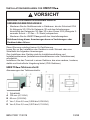
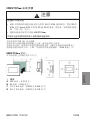
HMISTO5pp Cut-Outs
Cut-out dimensions for mounting on a flat surface:
1 Panel
A 105 mm (4.13 in.)
B 66 mm (2.60 in.)
C From 1.5 to 6.0 mm (0.059 to 0.236 in.)
R From 2.0 to 3.0 mm (0.079 to 0.118 in.)
CAUTION
ENVIRONMENTAL HAZARDS TO THE EQUIPMENT
• Mount the device in enclosure that meet the IP54 level of protection for
category 3G, IP6x for category 3D and the requirements relating to the
3G or 3D categories in Zones 2/22 (Category 3: normal level of protection
- G: Gas - D: Dust).
• Mount the HMISTO5pp according to the manufacturer's specifications.
Failure to follow these instructions can result in injury or equipment
damage.

6/88 BBV27900 11/2019
ENGLISH
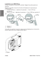
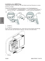
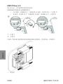
HMISTO5pp Installation
Spring clips hold the device in the enclosure.
Adjust the spring clips for the panel thickness by turning the spring clip over:
• 1.5 mm (0.059 in.) panel thickness 4 mm (0.157 in.) (position 1)
• 4 mm (0.157 in.) panel thickness 6 mm (0.236 in.) (position 2)
Lock the spring clips by pressing the clip’s top and bottom until you hear a click.
1 Position 1
2 Position 2
1 Click

BBV27900 11/2019 7/88
ENGLISH
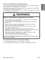
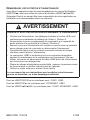
START-UP, OPERATION AND MAINTENANCE
You must follow all the recommendations described in the HMISTO5pp User
Manual and the HMISTUp55/p55W User Manual.
Schneider Electric cannot be held responsible for any application or installation
not recommended in these manuals.
This equipment is suitable for use in Class I, Division 2, Groups A, B, C and D
or non-hazardous locations only.
For HMISTO501/51p, interfaces are: COM1 and USB1.
For HMISTO53p, interfaces are: ETHERNET and USB1.
For HMISTUp55/p55W, interfaces are: COM1, ETHERNET and USB1.
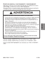
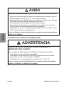
WARNING
RISK OF EXPLOSION IN HAZARDOUS LOCATIONS
• Verify the power, input, and output (I/O) wiring are in accordance with
Class I, Division 2 wiring methods.
• Do not substitute any components that impair compliance to Class I,
Division 2.
• Do not connect or disconnect equipment unless power has been
switched off or the area is non-hazardous.
• Securely lock externally connected units and each interface before
turning on the power supply.
• The USB2 connector is for temporary connection only during
maintenance and setup of the device. Do not use, connect, or disconnect
USB2 cable unless area is known to be non-hazardous.
• Potential electrostatic charging hazard: wipe the front panel of the
terminal with a damp cloth before turning ON.
• Use an insulated stylus to activate the touchscreen.
Failure to follow these instructions can result in death, serious injury,
or equipment damage.

8/88 BBV27900 11/2019
ENGLISH
CONNECTING THE POWER CORD
Before using your power cord verify the ground wire is the same gauge or
heavier than the power wires.
CAUTION
ENVIRONMENTAL HAZARDS TO THE EQUIPMENT
• Allow the device to reach the surrounding air temperature, not exceeding
50°C (122°F), before turning the device on.
• Do not turn on the device if condensation has occurred inside the device.
After it is completely dry again, the device may be turned on.
• Do not expose the device to direct sunlight.
• Do not obstruct the vents in the device casing.
• Remove any dust from the device before turning it on.
• Ensure that the cable installation fasteners are not damaged. Replace
them, if necessary.
Failure to follow these instructions can result in injury or equipment
damage.
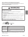
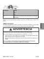
WARNING
SHORT CIRCUITS, FIRE, OR UNINTENDED EQUIPMENT
OPERATION
Use a power cord that meets the following requirements:
• Uses copper solid or stranded wires.
• Use D25CE/AZ5CE cable ends to short circuits.
• Uses wires that are 0.2 to 1.5 mm2 (24 - 16 AWG).
• Uses wires with a temperature rating of 75°C (167°F).
Failure to follow these instructions can result in death, serious injury,
or equipment damage.

BBV27900 11/2019 9/88
ENGLISH
Note: Mounting screws torque : 0.22 to 0.25 Nm (1.95 to 2.2 lb-in).
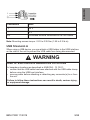
USB STANDARD A
When using a USB device, you can attach a USB holder to the USB interface
on the side of the unit to prevent the USB cable from being disconnected.
Connection Wire
+ 24 V
- 0 V
FG Grounded terminal connected to the unit chasis.
WARNING
RISK OF EXPLOSION IN HAZARDOUS LOCATIONS
In hazardous locations as described in ANSI/ISA - 12.12.01:
• confirm that the USB cable has been attached with the USB cable clamp
before using the USB host interface.
• remove power before attaching or detaching any connector(s) to or from
the unit.
Failure to follow these instructions can result in death, serious injury,
or equipment damage.

10/88 BBV27900 11/2019
ENGLISH
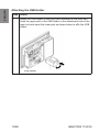
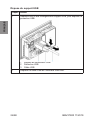
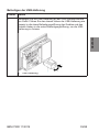
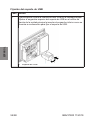
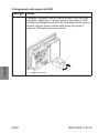
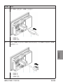
Attaching the USB Holder
Step Action
1Attach the USB holder to the USB Host Interface on the main unit.
Hook the upper pick of the USB holder to the attachment hole of the
main unit and insert the lower pick as shown below to affix the USB
holder.
1 USB holder

BBV27900 11/2019 11/88
ENGLISH
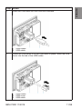
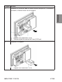
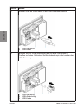
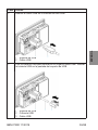
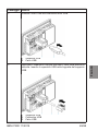
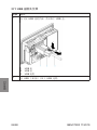
2Insert the USB cable into the USB host interface.
1 USB holder
2 USB cable
3Attach the USB cover to fix the USB cable in place. Insert the USB
cover into the tab of the USB holder.
1 USB holder
2 USB cover
3 USB cable
Step Action

12/88 BBV27900 11/2019
ENGLISH
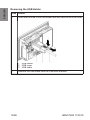
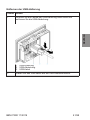
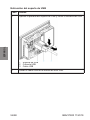
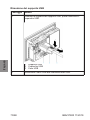
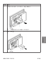
Removing the USB Holder
Step Action
1Push down the tab of the USB holder and then remove the USB cover.
1 USB holder
2 USB cover
3 USB cable
2Remove the USB cable from the USB host interface.

BBV27900 11/2019 13/88
ENGLISH
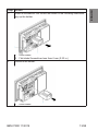
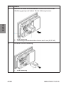
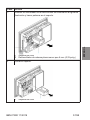
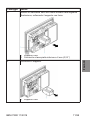
3Insert a screwdriver into the slot as shown in the following illustration,
pry up the holder.
1 USB holder
2 Flat-blade Screwdriver less than 6 mm (0.23 in.)
4Remove the holder.
1 USB holder
Step Action

14/88 BBV27900 11/2019
ENGLISH
RELATED DOCUMENTS
For further information, you can download the Harmony Small Panels User
Manuals and other technical information from our website at
www.schneider-electric.com

BBV27900 11/2019 15/88
FRANÇAIS
FICHE D'INSTRUCTIONS
pour HMISTO5pp et HMISTUp55/p55W
PROGRAMMATION D’ INTERFACE HOMME MACHINE (IHM)
Pour programmer les produits HMI Harmony STO/STU, téléchargez la version
de démonstration gratuite de Vijeo Designer1 sur www.schneider-electric.com:
1 Logiciel utilisé pour créer des données de projet de l’unité IHM.
Pour programmer tout autre produit Harmony, commandez Vijeo Designer
auprès de votre fournisseur Schneider Electric.
Remarque : Avant de charger une application sur un nouveau HMIS5T à l'aide
de Vijeo Designer V6.0 SP3 ou version ultérieure :
• Vérifiez que votre application est configurée pour utiliser le modèle cible
HMIS5T. Si tel n'est pas le cas, remplacez le modèle cible par HMIS5T
avant de procéder au chargement.
Ou
• Mettez Vijeo Designer au niveau de la version 6.1 pour éviter toute
utilisation malencontreuse.
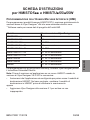
Modules Version minimale de Vijeo Designer
HMISTO501 6.0 ou ultérieur
HMISTO511/512 5.1 ou ultérieur
HMISTO531/532 6.0 SP1 ou ultérieur
HMISTU655 PV 04 5.1 ou ultérieur
HMISTU655 PV 04 6.1 SP1 ou ultérieur
HMISTU855 PV 03 5.1 SP2 ou ultérieur
HMISTU855 PV 03 6.1 SP1 ou ultérieur
HMISTU655W 6.1 SP1 ou ultérieur
HMISTU855W 6.1 SP1 ou ultérieur
HMIS5T 6.1 SP1 ou ultérieur

16/88 BBV27900 11/2019
FRANÇAIS
NORMES PERTINENTES
Ces produits ont été fabriqués conformément aux normes suivantes :
• Norme UL 508 et CSA C22.2 n°142 pour équipement de contrôle
industriel
• Norme ANSI/ISA - 12.12.01 et CSA C22.2 n°213 pour équipement
électrique à utiliser dans des emplacements dangereux de classe I,
division 2
Remarques : Les HMISTO5pp sont conçus pour être conformes aux règles de
la marine marchande.
Les appareils HMISTUp55/p55W sont conçus pour répondre aux exigences de
passerelle et de pont de la marine marchande (consultez le site web Schneider
pour les règles d'installation).
Les appareils HMISTO5pp et HMISTUp55/p55W doivent être installés, utilisés
et entretenus conformément aux normes suivantes :
• Norme DEEE, directive 2002/96/CE
• Norme RoHS, directive 2011/65/EU
• Norme RoHS Chine, norme SJ/T 11364-2014
HMIZSUKIT
Le kit d'accessoires pour le HMISTUp55/p55W contient :
• Support de câble USB standard type A
• Support mini USB B
• Téton antirotation
• Adaptateur de panneau
CONDITIONS REQUISES POUR L'INSTALLATION
A utiliser dans des environnements de degré de pollution 2.
Pour utilisation sur une surface plane d'un boîtier Type 13 et/ou Type 4X
(utilisation intérieure seulement).

BBV27900 11/2019 17/88
FRANÇAIS
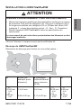
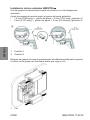
INSTALLATION DU HMISTUp55/p55W
Cet avis "Attention" n’est pas couvert par la certification UL.
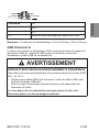
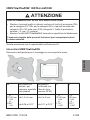
Découpe du HMISTUp55/p55W
Dimensions de découpe pour fixation sur une surface plane :;
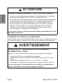
ATTENTION
RISQUES D'ENVIRONNEMENT POUR LES EQUIPEMENTS
• Montez les terminaux graphiques dans des boîtiers conformes au niveau
de protection IP54 pour les catégories 3G, IP6x pour la catégorie 3D et
les exigences relatives aux catégories 3G ou 3D dans des zones 2/22
(catégorie 3 : niveau de protection normal – G : Gaz – D : Poussière).
• Montez l'appareil HMISTUp55/p55W selon les spécifications du
constructeur.
Le non-respect de ces instructions peut entraîner des blessures ou des
dommages matériels.
A B (tôle, par
exemple, porte
d'armoire)
B (Plastiques
renforcés fibre de
verre, minimum
GF30)
CD
+0
22,50 mm
-0,30
+0
0,88 po
-0,01
1,5 à 6 mm
0,06 à 0,23 po
3 à 6 mm
0,11 à 0,23 po
+0
30,00 mm
-0,20
+0
1,18 po
-0,007
+0
4,00 mm
-0,20
+0
0,15 po
-0,007

18/88 BBV27900 11/2019
FRANÇAIS
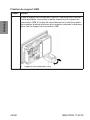
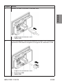
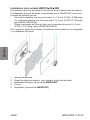
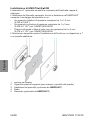
Installation du HMISTUp55/p55W
Le téton en option augmente la résistance de l'appareil au couple de rotation.
L'adaptateur pour panneau en option, fourni dans le HMIZSUKIT autorise le
montage du produit sur un :
• Support métallique d'épaisseur comprise entre 1 et 1,5 mm (0,039 et
0,059 po)
• Support plastique d'épaisseur comprise entre 1 et 3 mm (0,039 et
0,118 po) pour le HMISTU655/655W
• Plastique chargé fibre de verre d'épaisseur comprise entre 2 et 3 mm
(0,078 et 0,118 po) pour le HMISTU855/855W
L'illustration ci-dessous présente l'installation de l'appareil avec un téton et un
adaptateur de panneau :
1 Module d'affichage
2 Surface plane support (par exemple, porte d'armoire)
3 Adaptateur de panneau (en option avec le HMIZSUKIT)
4 Ecrou
5 Té (en option avec le HMIZSUKIT)

BBV27900 11/2019 19/88
FRANÇAIS
PROCÉDURES D'INSTALLATION DU HMISTO5pp
Cet avis "Attention" n’est pas couvert par la certification UL.
Lisez les instructions ci-dessous avant d'installer l'appareil dans une armoire
ou sur un panneau.
Le joint d'installation et les pièces de fixation (pour l'installation à l'aide des vis
et des attaches à ressort) sont requis pour installer l'appareil.
Installez le bornier dans un boîtier offrant un environnement propre, sec,
robuste et contrôlé (boîtier IP65).
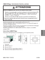
Découpe du HMISTO5pp:
Dimensions de découpe pour fixation sur une surface plane :
1 Panneau
A 105 mm (4,13 po)
B 66 mm (2,59 po)
C de 1,5 à 6,0 mm (0,059 à 0,236 po)
R de 2,0 à 3,0 mm (0,079 à 0,118 po)
ATTENTION
RISQUES D'ENVIRONNEMENT POUR LES EQUIPEMENTS
• Montez les terminaux graphiques dans des boîtiers conformes au niveau
de protection IP54 pour les catégories 3G, IP6x pour la catégorie 3D et
les exigences relatives aux catégories 3G ou 3D dans des zones 2/22
(catégorie 3 : niveau de protection normal – G : Gaz – D : Poussière).
• Montez l'appareil HMIST05pp selon les spécifications du constructeur.
Le non-respect de ces instructions peut entraîner des blessures ou des
dommages matériels.

20/88 BBV27900 11/2019
FRANÇAIS
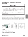
Installation du HMISTO5pp
Utilisez les agrafes à ressort pour maintenir l'appareil en place après son
insertion.
Réglez les agrafes à ressort en fonction de l'épaisseur du panneau par
retournement :
• 1,5 mm (0,059 po) épaisseur du panneau 4 mm (0,157 po)
(position 1)
• 4 mm (0,157 po) épaisseur du panneau 6 mm (0,236 po) (position 2)
Verrouillez les agrafes à ressort en appuyant simultanément sur le haut et le
bas de l'agrafe avec deux doigts jusqu'au déclic.
1 Position 1
2 Position 2
1 Cliquez
La pagina si sta caricando...
La pagina si sta caricando...
La pagina si sta caricando...
La pagina si sta caricando...
La pagina si sta caricando...
La pagina si sta caricando...
La pagina si sta caricando...
La pagina si sta caricando...
La pagina si sta caricando...
La pagina si sta caricando...
La pagina si sta caricando...
La pagina si sta caricando...
La pagina si sta caricando...
La pagina si sta caricando...
La pagina si sta caricando...
La pagina si sta caricando...
La pagina si sta caricando...
La pagina si sta caricando...
La pagina si sta caricando...
La pagina si sta caricando...
La pagina si sta caricando...
La pagina si sta caricando...
La pagina si sta caricando...
La pagina si sta caricando...
La pagina si sta caricando...
La pagina si sta caricando...
La pagina si sta caricando...
La pagina si sta caricando...
La pagina si sta caricando...
La pagina si sta caricando...
La pagina si sta caricando...
La pagina si sta caricando...
La pagina si sta caricando...
La pagina si sta caricando...
La pagina si sta caricando...
La pagina si sta caricando...
La pagina si sta caricando...
La pagina si sta caricando...
La pagina si sta caricando...
La pagina si sta caricando...
La pagina si sta caricando...
La pagina si sta caricando...
La pagina si sta caricando...
La pagina si sta caricando...
La pagina si sta caricando...
La pagina si sta caricando...
La pagina si sta caricando...
La pagina si sta caricando...
La pagina si sta caricando...
La pagina si sta caricando...
La pagina si sta caricando...
La pagina si sta caricando...
La pagina si sta caricando...
La pagina si sta caricando...
La pagina si sta caricando...
La pagina si sta caricando...
La pagina si sta caricando...
La pagina si sta caricando...
La pagina si sta caricando...
La pagina si sta caricando...
La pagina si sta caricando...
La pagina si sta caricando...
La pagina si sta caricando...
La pagina si sta caricando...
La pagina si sta caricando...
La pagina si sta caricando...
La pagina si sta caricando...
La pagina si sta caricando...
-
 1
1
-
 2
2
-
 3
3
-
 4
4
-
 5
5
-
 6
6
-
 7
7
-
 8
8
-
 9
9
-
 10
10
-
 11
11
-
 12
12
-
 13
13
-
 14
14
-
 15
15
-
 16
16
-
 17
17
-
 18
18
-
 19
19
-
 20
20
-
 21
21
-
 22
22
-
 23
23
-
 24
24
-
 25
25
-
 26
26
-
 27
27
-
 28
28
-
 29
29
-
 30
30
-
 31
31
-
 32
32
-
 33
33
-
 34
34
-
 35
35
-
 36
36
-
 37
37
-
 38
38
-
 39
39
-
 40
40
-
 41
41
-
 42
42
-
 43
43
-
 44
44
-
 45
45
-
 46
46
-
 47
47
-
 48
48
-
 49
49
-
 50
50
-
 51
51
-
 52
52
-
 53
53
-
 54
54
-
 55
55
-
 56
56
-
 57
57
-
 58
58
-
 59
59
-
 60
60
-
 61
61
-
 62
62
-
 63
63
-
 64
64
-
 65
65
-
 66
66
-
 67
67
-
 68
68
-
 69
69
-
 70
70
-
 71
71
-
 72
72
-
 73
73
-
 74
74
-
 75
75
-
 76
76
-
 77
77
-
 78
78
-
 79
79
-
 80
80
-
 81
81
-
 82
82
-
 83
83
-
 84
84
-
 85
85
-
 86
86
-
 87
87
-
 88
88


Schneider Electric HMISTU655 Istruzioni per l'uso
- Tipo
- Istruzioni per l'uso
- Questo manuale è adatto anche per
in altre lingue
Documenti correlati
-
Schneider Electric Harmony GTO Manuale utente
-
Schneider Electric SR2CBL01 Istruzioni per l'uso
-
-
Schneider Electric Zelio Logic 2 Manuale utente
-
-
Eurotherm TCSMCNAM3M002P USB to RS485 converter Manuale del proprietario
-