Climbing Technology 2D67400WBSH Istruzioni per l'uso
- Tipo
- Istruzioni per l'uso

Climbing Technology by Aludesign S.p.A. via Torchio 22
24034 Cisano B.sco BG ITALY www.climbingtechnology.com 1/54
Member of
cover
IST23-2D674CT_rev.1 03-23
8510
0333
0333
CRIC
EN 12841:2006-B
EN 567:2013
EN 12278:2007
PATENT PENDING
MADE IN ITALY
EN Multifunctional rope clamp with pulley.
IT Bloccante multifunzione con carrucola.
FR Bloqueur multifonctionnel avec poulie.
DE Multifunktionssteigklemme mit Seilrolle.
ES Bloqueador multifunción con polea.
PL Wielofunkcyjny zacisk linowy z kołem pasowym.
PT Braçadeira do cabo multifuncional com polia.
SE Multifunktionell repklämma med remskiva.
FI Monikäyttöinen köysikiinnitin hihnapyörällä.
NO Multifunksjonell tauklemme med trinse.
DK Multifunktionel rebklemme med remskive.
NL Multifunctionele touwblokkering met poelie.
SI Več funkcijska sponka za vrv s škripcem.
SK Multifunkčná lanová svorka s kladkou.
RO Clemă de coardă multifuncțională cu scripete.
CZ Multifunkční lanový třmen s kladkou.
HU Multifunkcionális kötélbilincs csigával.
GR Πολυλειτουργικός σφιγκτήρας σχοινιού με τροχαλία.
EE Multifunktsionaalne köiehaarats koos plokiga.
LV Daudzfunkcionālā virves skava ar trīsi.
LT Daugiafunkcinė virvės apkaba su skriemuliu.
BG Многофункционален въжен самохват с макара.
HR Višenamjenska stezaljka za uže s koloturom.
Regulation (EU) 2016/425
Personal Protective Equipment against falls from a height.
G
=+S

Climbing Technology by Aludesign S.p.A. via Torchio 22
24034 Cisano B.sco BG ITALY www.climbingtechnology.com 2/54
Member of
drawings
1MODELS
Model Cric Cric Cord
REF. No.
2D674 2D674KIT01
140 g 5g
g
2TECHNICAL DATA / COMPATIBILITY
Standards EN 12841-B EN 567 EN 12278
EN 1891-A
Ø 10÷12 mm
EN 1891
EN 892
EN 564
Ø 8÷12 mm
EN 1891
EN 892
EN 564
Ø ≤11 mm
Additional
data
Maximum
rated load:
Working
load limit
(WLL):
Maximum
guaranteed
strength:
100 kg 4 kN 20 kN
10 10
A
C
D
B
E
H
F
G
3NOMENCLATURE
C
R
I
C
Made in Italy
PAT. PEND.
BBBB
P
O
E
N
1
T1
10
6
11
19
4
31
8
12
30
T8
34
30
T3
T9
7
30
32
6
33
6
4MARKING
IST23-2D674CT_rev.1 03-23

Climbing Technology by Aludesign S.p.A. via Torchio 22
24034 Cisano B.sco BG ITALY www.climbingtechnology.com 3/54
Member of
STOP!
max
4 kN
PUSH
PUSH
CLICK!
CLICK!
5ASCENDER MODE - INSTALLATION AND TEST
5.1 - MODE 1 5.2 5.3 5.4 5.5 5.6 5.7
5.8 - MODE 2 5.9 5.10 5.11 5.12 5.13 5.14 - Test 5.15 - OK! 5.16 - EN 567
Working load limit
g
N
N
O
O
!
!
STOP!
6ASCENDER MODE - INSTRUCTIONS FOR USE AND RELEASING
6.1 - Instructions for use 6.2 - Releasing 6.3 - Warning about releasing
Rope adjustment
device: type A
- safety device -
Rope adjustment
device: type B
- ascender -
Cric
7ASCENDER MODE - EXAMPLE OF USE
EN 362 connector
EN 354 lanyard
IST23-2D674CT_rev.1 03-23

Climbing Technology by Aludesign S.p.A. via Torchio 22
24034 Cisano B.sco BG ITALY www.climbingtechnology.com 4/54
Member of
g
P
F
CLICK! 2,4 kN
1,2 kN 1,2 kN
20 kN
WORKING
LOAD LIMIT (WLL)
MAXIMUM
GUARANTEED
STRENGTH
10 kN 10 kN
8PULLEY MODE
8.1 8.2 8.3 - OK
8.4
8.6
8.78.5 - Use not covered by the standard EN 12278 / EN 17109
Theoretical force F=P
F=1,1P
F=2P
Self braking
descender
Belay - rappel
device or
Self braking
descender
Self-braking
descender
Cric
Cric
Belay -
rappel
device
Ø ≤12 mm
O
O
K
K
!
!
N
N
O
O
!
!
DANGER
Ø >12 mm
9ROPE CLAMP / PULLEY MODE
9.1 - Ascending configuration 9.2 - Example of ascending configuration
9.3 - Hauling configuration 9.4 - Example of hauling configuration 9.5
IST23-2D674CT_rev.1 03-23

Climbing Technology by Aludesign S.p.A. via Torchio 22
24034 Cisano B.sco BG ITALY www.climbingtechnology.com 5/54
Member of
STOP!
g
g
CLICK!
DANGER
N
N
O
O
!
!
10 PROGRESS CAPTURE PULLEY / HAULING CONFIGURATION
INSTRUCTIONS AND EXAMPLE OF USE
10.1 10.2 10.3 10.4 10.5 10.6
g g
1
2
g g g g
N
N
O
O
!
!
11 PROGRESS CAPTURE PULLEY / HAULING CONFIGURATION
RELEASING OF A LOAD
11.1 - Low loads releasing 11.2 - Heavy loads releasing 11.3 - Warning
IST23-2D674CT_rev.1 03-23

Climbing Technology by Aludesign S.p.A. via Torchio 22
24034 Cisano B.sco BG ITALY www.climbingtechnology.com 6/54
Member of
STOP!
12
PROGRESS CAPTURE PULLEY /
ASCENDING CONFIGURATION
TESTED UP TO Ø 11 mm ROPES
12.1 12.2
13 PROGRESS CAPTURE PULLEY / ASCENDING CONFIGURATION
ASCENDING A ROPE / CREVASSE RESCUE EXAMPLES
13.1 - Ascending a rope 13.2 - Crevasse rescue 13.3 - Crevasse rescue
IST23-2D674CT_rev.1 03-23

Climbing Technology by Aludesign S.p.A. via Torchio 22
24034 Cisano B.sco BG ITALY www.climbingtechnology.com 7/54
Member of
14 PROGRESS CAPTURE PULLEY / ASCENDING CONFIGURATION
WINCH SYSTEMS EXAMPLES
14.1 - Winch system 3:1 14.2 - Winch system 3:1 example 14.3 - Winch system 14.4 - Winch system
IST23-2D674CT_rev.1 03-23

Climbing Technology by Aludesign S.p.A. via Torchio 22
24034 Cisano B.sco BG ITALY www.climbingtechnology.com 8/54
Member of
N
N
O
O
!
!
N
N
O
O
!
!
DANGER
N
N
O
O
!
!
DANGER
N
N
O
O
!
!
DANGER
N
N
O
O
!
!
DANGER
N
N
O
O
!
!
DANGER
N
N
O
O
!
!
DANGER
15 WRONG USES
15.1 15.2 15.3
15.4 15.5 15.6
15.7
N
N
O
O
!
!
O
O
K
K
!
!
O
O
K
K
!
!
O
O
K
K
!
!
O
O
K
K
!
!
DANGER
N
N
O
O
!
!
N
N
O
O
!
!
N
N
O
O
!
!
-20 ÷ +104°F
-29 ÷ +40°C
DANGER
Mud, ice,
foreign
bodies,
etc. O
O
K
K
!
!
CLICK!
N
N
O
O
!
!
DANGER
16 WARNINGS
16.1 16.2 16.3 16.4 16.5 16.6
16.7 16.8 16.9 16.10 16.11
LOCK
17 CRIC CORD REPLACEMENT
17.1
17.2
17.3
17.4
IST23-2D674CT_rev.1 03-23

Climbing Technology by Aludesign S.p.A. via Torchio 22
24034 Cisano B.sco BG ITALY www.climbingtechnology.com 9/54
Member of IST23-2D674CT_rev.1 03-23
ENGLISH
The instruction manual for this device consists of general and specific instructions,
both must be carefully read and understood before use. Attention! This leaflet
shows the specific instruction only.
SPECIFIC INSTRUCTIONS CRIC.
This note contains the necessary information for a correct use of the following
product/s: multifunctional rope clamp with integrated pulley for mountaineering,
rope access work and rescue.
1) FIELD OF APPLICATION.
EN 12841:2006-B - Rope access system / Rope adjustment device type B /
Working line ascender. EN 567:2013 - Mountaineering equipment: rope clamps.
EN 12278:2007 - Mountaineering equipment: pulleys. This product is a personal
protective device (P.P.E.). It is compliant with the Regulation (EU) 2016/425.
Attention! According to EN 12841 standard, for this product the indications of
the standard EN 365 must be respected (general instructions / paragraph 2.5).
Attention! According to EN 12841standard, for this product a periodic thorough
inspection is compulsory (general instructions / paragraph 8). Danger of death!
This product is not a fall arrest device (EN 353-2 / EN 12841-A) and cannot be
used for self-belaying when climbing.
1.1 - Intended uses. The device is designed for prevention against falls from height
(EN 567 / EN 12841-B / EN 12278).
2) NOTIFIED BODIES.
Refer to the legend in the general instructions (paragraph 9 / table D): M6; N1.
3) NOMENCLATURE (Fig. 3).
A) Fixed side plate. B) Swinging side plate. C) Locking cam. D) Release button. E)
Hole for connection. F) Cam-opening cord. G) Sheave. H) Release button guard.
3.1 - Main materials. Refer to the legend in the general instructions (para-
graph 2.4): 1; 3; 7.
4) MARKING.
Numbers/letters without caption: refer to the legend in the general instruc-
tions (paragraph 5).
4.1 - General (Fig. 4). Indications:1; 4; 6; 7; 8; 10; 11; 12; 19; 30) Types and
diameters of compatible ropes; 31) Direction of opening; 32) Pictogram indicating that
the device includes pulleys mounted on ball bearings; 33) Maximum guaranteed strength; 34)
Maximum rated load.
4.2 - Traceability (Fig. 4). Indications: T1; T3; T8; T9.
5) COMPATIBILITY.
This product can only be used in combination with CE-marked equipment.
5.1 - Harnesses. This product is compatible with work harnesses (EN 813, EN
361) when used in compliance with EN 12841 and with mountaineering har-
nesses (EN 12277) when used in compliance with EN 567 and EN 12278.
5.2 - Ropes / accessory cords. Depending on the relevant legislation, the equip-
ment can only be used with the ropes and/or accessory cords listed in the table
(Fig. 2): EN 1891 semi-static kernmantle (core + sheath) ropes, EN 892 dynamic
ropes, EN 564 accessory cords. For the certification to the EN 12841 standard,
the following ropes have been used: Patron 10 and Patron 12 (Teufelberger). At-
tention! Do not use on wire ropes or braided ropes. Attention! In compliance with
EN 12841-B, the device can be connected to the EN 813 attachment point of
the harness using an EN 354 lanyard and compatible EN 362 connectors (Fig.
7): maximum total length = 1 m.
5.3 - Connector. Only use an EN 362 connector (mandatory for use in accord-
ance with EN 12841) or an EN 12275 connector equipped with a locking gate
in the hole for connection and with maximal length 110 mm. Attention! Make
sure that the connector in use allows the device to work in-line (Fig. 16.3) without
hindering its correct positioning (Fig. 16.4).
6) CHECKS.
Further to the checks listed below, comply with what indicated in the general
instructions (paragraph 3). Before each use, verify that: the cam rotates freely,
without jamming and the spring of the cam snaps it in the rope locking position;
all teeth of the cam are present and without any sign of wear; the pulley rotates
freely in both directions. During each use: always verify the correct placement of
the rope inside the device; the device and the rope must not lean against or get in
touch with cutting edges and abrasive materials (Fig. 16.6-16.8); ensure the rope
is always in tension to avoid possible free-falls; avoid having slack rope between
the anchor and the attachment on the harness.
7) ISTRUCTIONS FOR USE.
This device can be used in several modes: 1) Ascender (Fig. 5÷7); 2) Pulley (Fig.
8); 3) Rope clamp/pulley (Fig. 9); 4) Progress-capture hauling pulley (Fig. 10÷14).
7.1 - Warnings. 1) For user safety, it is essential that the device or the anchor
point are always positioned correctly and the work carried out in such a way as to
minimize the risk of falling and the height of fall. 2) Do not use connection methods
of the device other than those indicated.
8) ASCENDER MODE.
This mode allows ascending the rope in accordance with EN 567 / EN 12841-
B (e.g. rope ascent in rope access work - Fig. 7).
8.1 - Installation. Press the release button and rotate the swinging side plate as
shown (Fig. 5.1÷5.2 / 5.8÷5.9). Hold the rope slightly tensioned with one
hand and, while doing so, place the device behind the rope using the other hand
(Fig. 5.3). Push the device along the rope while keeping the rope in contact with
the locking cam, in order to make it open (Fig. 5.4) so as to allow the rope to
properly sit inside the device (Fig. 5.5). Alternatively, the cam can be opened
using the thumb, before inserting the rope inside the device (Fig. 5.10÷5.11).
Rotate the swinging side plate back to its initial position, as shown, until when
a ‘click’ - indicating it closed fully - can be heard (Fig. 5.6-5.12-16.10). Secure
a compatible connector into the dedicated hole for connection (Fig. 5.7-5.13).
Finally, perform a functional test of the device to verify its good functioning and the
correct direction of assembly of the rope (Fig. 5.14÷5.15). Attention! To remove
the rope, open the swinging side plate and, using a thumb, rotate the cam so as
to allow the rope to come out. Alternatively, open the swinging side plate and,
while holding the rope slightly taut, push and tilt the device so as to make the cam
open and the rope come out of its place.
8.2 - Use. The device is free to move upward and will lock in the position on
which is placed (Fig. 6.1). Be careful when approaching anchors and/or inter-
mediate anchors. Under no circumstances should the device be used in situations
with a potential fall factor greater than 1 (Fig. 16.2), i.e. the user must - at all times
- be located below the device and/or the anchor point (Fig. 16.1). Attention! A
fall with a fall factor greater than 1 could make the rope break. Attention! When
ascending a vertical rope, the device must be used in combination with another
rope-clamping device secured to the harness.
8.3 - Releasing. The device can be moved along the line in the opposite direc-
tion with respect to the direction of use: 1) Completely unload the device; 2)
Disengage the locking cam from the rope by pulling the cam-opening cord in the
direction shown in figure (Fig. 6.2); 3) Slide the device along the line while pulling
the cam-opening cord as shown (Fig. 6.2); 4) Finally, let go of the cord and put
the device back under load. Attention! Do not carry out these manoeuvres when
the device is under load (Fig. 6.3).
8.4 - EN 12841-B warnings. 1) The primary function of Type-B rope adjustment
devices is the progression up the work line; for this reason, it is essential that they
are always used together with a Type-A rope adjustment device connected to an
independent safety line. 2) Rope adjustment devices are not suitable for use in
a fall arrest system. 3) When an adjustable anchor line is loaded with the entire
weight of the user, it becomes a work line: to ensure the optimal safety of the user
it is therefore necessary that a safety line is used as well. 4) Only anchor points
that comply with the EN 795 standard can be used (minimum strength 12 kN or
18 kN for non-metallic anchors) that do not have sharp edges. 5) Avoid any over-
loading or dynamic loading on the device because can harm the anchor line. 6)
The technical performances of the anchor line might vary considerably, due to dirt,
moisture, ice, repeated uses on the same stretch: beware, because these changes
in condition can affect the integrity of the line and the locking performance of the
device on the rope. 7) There are no restrictions on the inclination of the anchor
rope. Nonetheless it is recommended to work as vertically as possible with the
anchor point, in order to limit the risk of a pendulum effect. 8) Different types of
anchor lines can affect the characteristics and the safe operation of the device. 9)
Maximum rated load: 100 kg.
9) PULLEY MODE.
This mode allows the lifting or transferring of a load in accordance with the EN
12278 standard. Attention! The use on tensioned highlines/Tyrolean traverses is
not covered by the EN 12278 nor EN 17109 standards (Fig. 8.5): in case of
such use, check the compatibility of the equipment with the line set-up by carrying
out the necessary tests (e. tension, inclination, distance between anchors, etc.).
9.1 - Installation. Press the release button and rotate the swinging side plate.
Install the rope on the sheave as shown (Fig. 8.1). Rotate the swinging side plate
back to its initial position, as shown, until when a ‘click’ - indicating it is fully closed
- can be heard (Fig. 8.2). Secure a compatible connector through the dedicated
hole for connection (Fig. 8.3).
9.2 - Efficiency (Fig. 8). Theoretically, the force (F) required to lift a weight (P) is
equal to the weight itself (F = P). In the real world, on the other hand, frictions do
exist and the force F required is actually greater: F=1.1P (example using Cric); F
= 2P (example using connector).
9.3 - Warnings. The stress on the anchor point and on the other elements of the
system can increase considerably due to the dynamic movements of the load
during the manoeuvre: verify the overall resistance of the system.
10) ROPE CLAMP/PULLEY MODE.
This mode offers two different configurations of use in which the device is in
a fixed position on the line and it allows the use of the pulley to create a haul
system. For the installation, follow the relevant drawings (Fig. 9.1-9.3) while ad-
hering to the instructions given in the previous paragraphs for the opening/clos-
ing of the device.
10.1 - Ascending configuration. The equipment, used in combination with a
self-braking descender, allows the user to ascend a rope, creating a hoist that can
reduce the effort required by the user to ascend the rope (Fig. 9.2).
10.2 - Hauling configuration: aid or simple haul systems. The equipment, used in

Climbing Technology by Aludesign S.p.A. via Torchio 22
24034 Cisano B.sco BG ITALY www.climbingtechnology.com 10/54
Member of IST23-2D674CT_rev.1 03-23
combination with a belay/rappel device or a self-braking descender, allows the
hauling of a person (Fig. 9.4) thanks to the mechanical advantage obtained with
respect to the load/person. This manoeuvre reduces the effort required to help the
person in difficulty. The equipment can be used to create rescue systems with high-
er mechanical advantage in case of heavier loads.Attention! Carefully evaluate
the strength of the line and the amount of friction during the rescue operations;
maximum load of the device: 4 kN (Fig. 9.4). Attention! Absolutely avoid using a
working line with a diameter that keeps the cam in the open position, thus causing
interference between the cam itself and the rope placed onto the pulley (Fig. 9.5).
11) PROGRESS-CAPTURE HAULING PULLEY MODE.
This mode offers two different configurations of use in which the rope is free to
move through the device in one direction and is locked in the opposite one. For
the installation, follow the relevant drawings (Fig. 10.4-12.1) while adhering to
the instructions given in the previous paragraphs for the opening/closing of the
device. Attention! In the configuration for ascending, the device has been tested
for use with ropes Ø ≤ 11 mm.
11.1 - Hauling configuration. The equipment allows the direct lifting of a load
(Fig. 10.6). Attention! This product is not an EN 15151 belay device and should
not be used for belaying a person. If necessary, it is also possible to release and
lower the load, whether light (Fig. 11.1) or heavy (Fig. 11.2) by inserting an
additional connector. In both cases, before proceeding with the manoeuvre, it is
necessary to release the cam from the load: 1) Pull the free rope and lift slightly the
load; 2) Hold the load in position; 3) With one hand pull the cam-opening cord
and with the other slowly lower the load. Attention! While lowering the load, it is
necessary to hold with one hand the side of the rope not connected to the load,
at all times (Fig. 11.3). Attention! If needed, it is possible to tie a friction hitch to
control the lowering speed.
11.2 - Ascending configuration. The equipment allows the hauling (Fig. 13.3) or
self-rescue of a person (Fig. 13.1), for example in case of a fall into a crevasse.
The equipment can also be used to create haul systems (Fig. 14).
12) SYMBOLS.
Refer to the legend in the general instructions (paragraph 16): F1; F2; F3; F7; F9.
13) REPLACEMENT PARTS.
This product is compatible only with with the spare parts and specific acces-
sories listed below: cam-opening cord (Mod. Cric Cord). Attention! This spare
part by itself doesn’t constitute a PPE. To replace it, follow the procedure, as
shown (Fig. 17): before using the equipment, make sure that the cord has been
installed correctly.

Climbing Technology by Aludesign S.p.A. via Torchio 22
24034 Cisano B.sco BG ITALY www.climbingtechnology.com 11/54
Member of IST23-2D674CT_rev.1 03-23
ITALIANO
Le istruzioni d’uso di questo dispositivo sono costituite da un’istruzione generale e
da una specifica ed entrambe devono essere lette attentamente prima dell’utiliz-
zo. Attenzione! Questo foglio costituisce solo l’istruzione specifica.
ISTRUZIONI SPECIFICHE CRIC.
Questa nota contiene le informazioni necessarie per un utilizzo corretto del se-
guente prodotto/i: bloccante multifunzione con carrucola per alpinismo, lavoro
su fune e soccorso.
1) CAMPO DI APPLICAZIONE.
EN 12841:2006-B - Sistemi di accesso con fune / Dispositivi di regolazione
della fune di tipo B / Risalitore della linea di lavoro. EN 567:2013 - Attrezzatura
per alpinismo: bloccante. EN 12278:2007 - Attrezzatura per alpinismo: puleg-
ge. Questo prodotto è un dispositivo di protezione individuale (D.P.I.); esso è
conforme al regolamento (UE) 2016/425. Attenzione! In accordo con la norma-
tiva EN 12841 per questo prodotto devono essere rispettate le indicazioni della
norma EN 365 (istruzioni generali / paragrafo 2.5). Attenzione! In accordo
con la normativa EN 12841, per questo prodotto è obbligatorio un controllo
periodico approfondito (istruzioni generali / paragrafo 8). Pericolo di morte!
Questo prodotto non è un dispositivo anticaduta (EN 353-2 / EN 12841-A) né
può essere utilizzato per l’autoassicurazione in arrampicata.
1.1 - Destinazioni d’uso. Il dispositivo è progettato per la prevenzione contro le
cadute dall’alto (EN 567 / EN 12841-B / EN 12278).
2) ORGANISMI NOTIFICATI.
Consultare la legenda nelle istruzioni generali (paragrafo 9 / tabella D): M6; N1.
3) NOMENCLATURA (Fig. 3).
A) Guancia fissa. B) Guancia mobile. C) Camma di bloccaggio. D) Pulsante di
apertura. E) Foro di collegamento. F) Cordino di apertura camma. G) Puleggia.
H) Protezione pulsante di apertura.
3.1 - Materiali principali. Consultare la legenda nelle istruzioni generali (para-
grafo 2.4): 1; 3; 7.
4) MARCATURA.
Numeri/lettere senza didascalia: consultare la legenda nelle istruzioni genera-
li (paragrafo 5).
4.1 - Generale (Fig. 4). Indicazioni: 1; 4; 6; 7; 8; 10; 11; 12; 19; 30) Tipologia
e diametri di corde compatibili; 31) Senso di apertura; 32) Pittogramma indicante
che il dispositivo include pulegge su cuscinetti a sfera; 33) Resistenza massima
garantita; 34) Carico nominale massimo.
4.2 - Tracciabilità (Fig. 4). Indicazioni: T1; T3; T8; T9.
5) COMPATIBILITÀ.
Questo prodotto è utilizzabile solamente con dispositivi marchiati CE.
5.1 - Imbracature. Questo prodotto è compatibile con imbracature da lavoro
(EN 813, EN 361) quando utilizzato in conformità alla norma EN 12841 e con
imbracature da alpinismo (EN 12277) quando utilizzato in conformità alle norme
EN 567 e EN 12278.
5.2 - Corde / cordini. A seconda della normativa, il dispositivo può essere uti-
lizzato solo con le corde e/o cordini indicati in tabella (Fig. 2): corde semista-
tiche (anima + calza) EN 1891, corde dinamiche EN 892, cordini EN 564.
Per la certificazione EN 12841 sono state utilizzate le seguenti corde: Patron
10 e Patron 12 (Teufelberger). Attenzione! Non utilizzare su cavo metallico o
corda intrecciata. Attenzione! In conformità alla EN 12841-B il dispositivo può
essere collegato al punto di attacco EN 813 dell‘imbracatura mediante un cor-
dino EN 354 e dei connettori EN 362 compatibili (Fig. 7): lunghezza tota-
le massima = 1 m.
5.3 - Connettore. Nel foro di collegamento del dispositivo utilizzare esclusiva-
mente un connettore EN 362 (obbligatorio per l’uso secondo EN 12841) o EN
12275 provvisto di ghiera di bloccaggio e di lunghezza massima 110 mm.
Attenzione! Verificare che il connettore utilizzato consenta al dispositivo di lavo-
rare in asse (Fig. 16.3) e non ne ostacoli il corretto posizionamento (Fig. 16.4).
6) CONTROLLI.
Oltre ai controlli indicati di seguito rispettare quanto indicato nelle istruzioni gene-
rali (paragrafo 3). Prima di ogni utilizzo verificare che: la camma di bloccaggio
ruoti liberamente senza impuntamenti e la molla della camma la faccia scattare in
posizione di blocco corda; i denti della camma siano tutti presenti e senza usura;
la puleggia sia libera di ruotare in entrambe le direzioni. Durante ogni utilizzo:
verificare sempre il corretto posizionamento della corda all’interno del dispositivo;
evitare che il dispositivo o la corda, appoggino o sfreghino su parti taglienti e
materiali abrasivi (Fig. 16.6-16.8); assicurarsi che la corda rimanga tesa per
limitare eventuali cadute; evitare che tra l’ancoraggio e l’utilizzatore si formino
allentamenti della corda.
7) ISTRUZIONI D’USO.
Il dispositivo può essere usato in varie modalità: 1) Risalitore (Fig. 5÷7); 2)
Carrucola (Fig. 8); 3) Bloccante/carrucola (Fig. 9); 4) Carrucola da recupe-
ro (Fig. 10÷14).
7.1 - Avvertenze. 1) Durante l’utilizzo è essenziale, per la sicurezza dell’operato-
re, che il dispositivo o il punto di ancoraggio siano sempre correttamente posizio-
nati e che il lavoro sia effettuato in modo da ridurre al minimo il rischio di caduta
e l’altezza di caduta. 2) Non utilizzare metodi di collegamento del dispositivo
diversi da quelli indicati.
8) MODALITÀ RISALITORE.
Questa modalità permette la risalita su corda in conformità alle norme EN 567 /
EN 12841-B (es. risalita durante il lavoro su fune - Fig. 7).
8.1 - Installazione. Premere il pulsante di apertura e ruotare la guancia mobile
come indicato (Fig. 5.1÷5.2 / 5.8÷5.9). Tenere la corda leggermente in tensio-
ne con una mano e con l’altra posizionare il dispositivo dietro la corda (Fig. 5.3).
Spingere il dispositivo lungo la corda mantenendola in contatto con la camma di
bloccaggio, in modo che la stessa si apra (Fig. 5.4) e la corda si posizioni suc-
cessivamente all’interno del dispositivo (Fig. 5.5). In alternativa è possibile utiliz-
zare il pollice per aprire la camma e successivamente inserire la corda all’interno
del dispositivo (Fig. 5.10÷5.11). Chiudere la guancia mobile come indicato fino
ad avvertire il click di corretta chiusura (Fig. 5.6-5.12-16.10). Inserire un con-
nettore compatibile nell’apposito foro di collegamento (Fig. 5.7-5.13). Eseguire
infine un test di funzionamento del dispositivo per verificarne il corretto funziona-
mento e il corretto senso di montaggio della corda (Fig. 5.14÷5.15). Attenzione!
Per togliere la corda aprire la guancia mobile e, utilizzando il pollice, ruotare la
camma permettendo la fuoriuscita della corda. In alternativa aprire la guancia
mobile e, tenendo la corda leggermente tesa, spingere e inclinare il dispositivo in
modo che la camma si apra e la corda esca dalla sua sede.
8.2 - Utilizzo. Il dispositivo è libero di scorrere verso l’alto e si blocca nella po-
sizione in cui si colloca (Fig. 6.1). Prestare attenzione nell’avvicinamento a punti
di ancoraggio e/o frazionamento. In nessun caso il dispositivo dovrà essere
utilizzato in situazioni con fattori di caduta potenziali superiori a 1 (Fig. 16.2),
ovvero l’utilizzatore dovrà trovarsi sempre al di sotto del dispositivo e/o del punto
di ancoraggio (Fig. 16.1). Attenzione! Una caduta con fattore superiore a 1
potrebbe causare la rottura della corda. Attenzione! In caso di risalita su corda
verticale, il dispositivo va utilizzato in combinazione con un altro dispositivo bloc-
cante collegato all’imbracatura.
8.3 - Rilascio. Il dispositivo può essere spostato lungo la linea nella direzione
contraria al senso di utilizzo: 1) Scaricare totalmente il dispositivo dal carico; 2)
Sganciare la camma dalla corda tirando il cordino di apertura nella direzione in-
dicata (Fig. 6.2); 3) Spostare il dispositivo lungo la linea tenendo tirato il cordino
di apertura come indicato (Fig. 6.2); 4) Rilasciare infine il cordino e riapplicare il
carico. Attenzione! Non effettuare l’operazione con carico applicato (Fig. 6.3).
8.4 - Avvertenze EN 12841-B. 1) La funzione primaria dei dispositivi di rego-
lazione della fune di tipo B è la progressione lungo la linea di lavoro ed è
quindi necessario che essi vengano sempre utilizzati unitamente a un dispositivo
di regolazione della fune di tipo A connesso ad una linea di sicurezza indipen-
dente. 2) I dispositivi di regolazione della fune non sono idonei all’utilizzo in
un sistema di arresto caduta. 3) Quando una linea di ancoraggio regolabile è
caricata dell’intero peso dell’utilizzatore, essa diventa una linea di lavoro: per la
sicurezza ottimale dell’utilizzatore è quindi necessario utilizzare in aggiunta una
linea di sicurezza. 4) Utilizzare esclusivamente punti di ancoraggio, conformi alla
norma EN 795 (resistenza minima 12 kN o 18 kN per ancoraggi non metallici),
che non presentino spigoli taglienti. 5) Evitare qualsiasi sovraccarico o carico
dinamico sul dispositivo di regolazione perché potrebbe danneggiare la linea
di ancoraggio. 6) Le caratteristiche della linea di ancoraggio possono variare
durante l’utilizzo, a causa di usura, sporco, umidità o utilizzi ripetuti sulla stessa
parte della linea: prestare attenzione perché queste condizioni possono influire
sull’integrità della linea e sulle performance di bloccaggio del dispositivo. 7) Non
sono previste limitazioni all’inclinazione della linea di ancoraggio. Ciononostan-
te, al fine di limitare l’effetto pendolo, è consigliabile operare il più possibile sulla
verticale del punto di ancoraggio. 8) Tipi diversi di linee di ancoraggio possono
cambiare le caratteristiche e il funzionamento sicuro del dispositivo. 9) Carico
nominale massimo: 100 kg.
9) MODALITÀ CARRUCOLA.
Questa modalità permette il sollevamento o il trasferimento di un carico in confor-
mità alla norma EN 12278. Attenzione! L’utilizzo per teleferica/tirolese non è
coperto dalle normative EN 12278 né EN 17109 (Fig. 8.5): in caso di impiego
verificare la compatibilità del dispositivo con l’installazione della linea effettuando
i test necessari (es. tensione, inclinazione, distanza fra gli ancoraggi etc.)..
9.1 - Installazione. Premere il pulsante di apertura e aprire la guancia mobile.
Installare la corda sulla puleggia come mostrato (Fig. 8.1). Chiudere la guancia
mobile come indicato fino ad avvertire il click di corretta chiusura (Fig. 8.2).
Inserire un connettore compatibile nell’apposito foro di collegamento (Fig. 8.3).
9.2 - Rendimento (Fig. 8). A livello teorico la forza (F) necessaria a sollevare
un peso (P) è uguale al peso stesso (F = P). Nell’uso reale esistono invece degli
attriti e la forza F da applicare è maggiore: F = 1,1P (esempio con Cric); F = 2P
(esempio con connettore).
9.3 - Avvertenze. Le sollecitazioni sul punto di ancoraggio e sugli altri elementi
del sistema possono aumentare notevolmente a causa dei movimenti dinamici
del carico durante la manovra: verificare la resistenza complessiva del sistema.
10) MODALITÀ BLOCCANTE/CARRUCOLA.
Questa modalità presenta due diverse configurazioni di utilizzo in cui il disposi-

Climbing Technology by Aludesign S.p.A. via Torchio 22
24034 Cisano B.sco BG ITALY www.climbingtechnology.com 12/54
Member of IST23-2D674CT_rev.1 03-23
tivo assume una posizione fissa sulla linea e permette di utilizzare la carrucola
per creare un paranco. Per l’installazione attenersi agli schemi rappresentati (Fig.
9.1-9.3) seguendo le indicazioni di apertura e chiusura del dispositivo indicate
nei paragrafi precedenti.
10.1 - Configurazione risalita. Il dispositivo, utilizzato in combinazione con un
discensore autofrenante, permette la risalita di una corda, creando un paranco
in grado di diminuire lo sforzo necessario da parte dell’utilizzatore per risalire la
corda stessa (Fig. 9.2).
10.2 - Configurazione paranco d’aiuto o paranco semplice. Il dispositivo, uti-
lizzato in combinazione con un assicuratore/discensore o un discensore auto-
frenante, permette il sollevamento di una persona (Fig. 9.4) mediante la demol-
tiplicazione del carico della persona stessa. Questa operazione riduce lo sforzo
necessario ad aiutare la persona in difficoltà. Il dispositivo può essere utilizzato
per creare sistemi di recupero con demoltiplica più elevata nel caso di carichi
più gravosi. Attenzione! Valutare attentamente la resistenza della linea e gli attriti
durante le operazioni di recupero; carico massimo del dispositivo 4 kN (Fig. 9.4).
Attenzione! Evitare assolutamente che il diametro della linea di lavoro mantenga
la camma in posizione aperta, causando in questo modo interferenza tra la cam-
ma stessa e la corda posizionata sulla carrucola (Fig. 9.5).
11) MODALITÀ CARRUCOLA DA RECUPERO.
Questa modalità presenta due diverse configurazioni nelle quali la corda è li-
bera di scorrere in una direzione e si blocca in quella opposta. Per l’installazio-
ne attenersi agli schemi rappresentati (Fig. 10.4-12.1) seguendo le indicazioni
di apertura e chiusura del dispositivo indicare nei paragrafi precedenti. Atten-
zione! Nella configurazione risalita il dispositivo è stato testato per l’uso con
corde Ø ≤ 11 mm.
11.1 - Configurazione sollevamento. Il dispositivo permette il sollevamento di-
retto di un carico (Fig. 10.6). Attenzione! Questo prodotto non è un dispositivo
di assicurazione EN 15151 e non deve essere utilizzato per l’assicurazione di
una persona. In caso di necessità è possibile anche rilasciare e calare il carico,
sia esso leggero (Fig. 11.1) o pesante (Fig. 11.2) mediante l’inserimento di un
connettore addizionale. In entrambi i casi, prima di procedere con la manovra,
è necessario sgravare la camma dal carico: 1) Tirare la corda libera e sollevare
leggermente il carico; 2) Trattenere il carico in posizione; 3) Con una mano tirare
il cordino di apertura camma e con l’altra calare lentamente il carico stesso.
Attenzione! Durante la calata è necessario tenere sempre in mano la corda sca-
rica (Fig. 11.3). Attenzione! In caso di necessità è possibile impiegare un nodo
autobloccante per gestire la velocità di calata.
11.2 - Configurazione risalita. Il dispositivo permette il sollevamento (Fig. 13.3)
o l’auto-sollevamento di una persona (Fig. 13.1), ad esempio nel caso di ca-
duta in un crepaccio. Il dispositivo può essere inoltre utilizzato per creare dei
paranchi (Fig. 14).
12) SIMBOLI.
Consultare la legenda nelle istruzioni generali (paragrafo 16): F1; F2; F3; F7; F9.
13) PARTI DI RICAMBIO.
Questo prodotto è compatibile solo con le seguenti parti di ricambio: cordino di
apertura camma (Mod. Cric Cord). Attenzione! Questa parte di ricambio da sola
non costituisce un DPI. Per la sostituzione eseguire quanto rappresentato (Fig. 17):
prima dell’utilizzo verificare che il cordino sia correttamente installato.

Climbing Technology by Aludesign S.p.A. via Torchio 22
24034 Cisano B.sco BG ITALY www.climbingtechnology.com 13/54
Member of IST23-2D674CT_rev.1 03-23
FRANÇAIS
Les instructions d’utilisation de ce dispositif comprennent une partie générale et une
partie spécifique, lesquelles doivent toutes les deux être lues attentivement avant
utilisation. Attention ! La présente fiche ne contient que les instructions spécifiques.
INSTRUCTIONS SPÉCIFIQUES CRIC.
Cette note contient les informations nécessaires à l’utilisation correcte du produit/s
suivant/s : bloqueur multifonctionnel avec poulie pour l’alpinisme, le sauvetage
et les travaux sur corde.
1) CHAMP D’APPLICATION.
EN 12841:2006-B - Systèmes d’accès par corde / Dispositifs de réglage de la
corde de type B / Dispositif d’ascension de la ligne de travail. EN 567:2013
- Équipement pour l’alpinisme: bloqueur. EN 12278:2007 - Équipement pour
l’alpinisme: poulies. Ce produit est un dispositif de protection individuelle (E.P.I.) ;
il est conforme au Règlement (UE) 2016/425. Attention ! Pour une utilisation
conforme à la norme EN 12841 pour ce produit il faut respecter les indications
de la norme EN 365 (instructions générales / paragraphe 2.5). Attention !
Pour une utilisation conforme à la norme EN 12841, une inspection périodique
approfondie est obligatoire pour ce produit (instructions générales / paragraphe
8). Danger de mort ! Ce produit n’est pas un dispositif antichute (EN 353-2 / EN
12841-A) et ne peut pas être utilisé pour l’auto-assurage en escalade.
1.1 - Destination. Le dispositif a été réalisé pour protéger contre les chutes en
hauteur (EN 567 / EN 12841-B / EN 12278).
2) ORGANISMES NOTIFIÉS.
Consulter la légende dans les instructions générales (paragraphe 9 / ta-
bleau D) : M6 ; N1.
3) NOMENCLATURE (Fig. 3).
A) Flasque fixe. B) Flasque mobile. C) Came de blocage. D) Bouton d’ouverture.
E) Trou de connexion. F) Cordelette d’ouverture came. G) Poulie. H) Protection
bouton d’ouverture.
3.1 - Matériaux principaux. Consulter la légende dans les instructions générales
(paragraphe 2.4) : 1 ; 3 ; 7.
4) MARQUAGE.
Chiffres/lettres sans légende : consulter la légende dans les instructions générales
(paragraphe 5).
4.1 - Général (Fig. 4). Indications : 1 ; 4 ; 6 ; 7 ; 8 ; 11 ; 12 ; 19 ; 30) Types et
diamètres de cordes compatibles ; 31) Sens d’ouverture ; 32) Pictogramme indi-
quant que le dispositif inclut des poulies avec roulement à billes ; 33) Résistance
maximale garantie; 34) Charge nominale maximale.
4.2 - Traçabilité (Fig. 4). Indications : T1 ; T3 ; T8 ; T9.
5) COMPATIBILITÉ.
Ce produit peut être utilisé seulement avec des dispositifs marqués CE.
5.1 - Harnais. Ce produit est compatible avec les harnais de travail (EN 813,
EN 361) quand il est utilisé conformément à la norme EN 12841 et avec les
harnais d’alpinisme (EN 12277) quand il est utilisé conformément aux normes
EN 567 et EN 12278.
5.2 - Cordes / longes. Selon la norme, le dispositif peut être utilisé uniquement
avec les cordes et/ou les longes indiquées dans le tableau (Fig. 2) : cordes semi
statiques (âme + gaine) EN 1891, cordes dynamiques EN 892, longes EN 564.
Les cordes suivantes ont été utilisées pour la certification EN 12841 : Patron 10 et
Patron 12 (Teufelberger). Attention ! Ne pas utiliser sur câble métallique ou corde
tressée. Attention ! Conformément à la norme EN 12841-B, le dispositif peut
être accroché au point d’ancrage EN 813 du harnais par une longe EN 354 et
de connecteurs EN 362 compatibles (Fig. 7) : longueur totale maximale = 1 m.
5.3 - Connecteur. Dans le trou de connexion du dispositif, utiliser exclusivement un
connecteur EN 362 (obligatoire pour l’utilisation selon la norme EN 12841) ou
EN 12275 avec bague de blocage et longueur maximale de 110 mm. Atten-
tion ! Vérifiez que le connecteur utilisé permet au dispositif de fonctionner symé-
triquement (Fig.16.3) et n’empêche pas son positionnement correct (Fig. 16,4).
6) CONTRÔLES.
En plus des contrôles indiqués en suite, il faut respecter ce qui est indiqué dans
les instructions générales (paragraphe 3). Avant chaque utilisation vérifier que :
la came de blocage tourne librement sans s’arrêter, le ressort de la came doit
la faire fonctionner dans la position de bloque corde ; les goujons de la came
soient tous présents et sans des signes d’usure ; la poulie puisse tourner librement
dans les deux directions. Pendant chaque utilisation : vérifier toujours le correct
positionnement de la corde à l’intérieur du dispositif ; éviter que le dispositif ou la
corde appuient ou frottent sur des parties coupantes et des matériaux abrasifs (Fig.
16.6-16.8) ; s’assurer que la corde reste tendue dans le but de limiter les chutes ;
éviter qu’il y ait des relâches de corde entre le point d’ancrage et l’utilisateur.
7) INSTRUCTIONS D’UTILISATION.
Le dispositif peut être utilisé dans des différents modalités : 1) Dispositif d’ascen-
sion (Fig. 5÷7) ; 2) Poulie (Fig. 8) ; 3) Bloqueur/poulie (Fig. 9) ; 4) Poulie de
récupération (Fig. 10÷14).
7.1 - Avertissements. 1) Lors de l’utilisation, il est essentiel, pour la sécurité de
l’opérateur, que le dispositif ou le point d’ancrage soient toujours correctement
positionnés et que le travail soit effectué de manière à réduire au minimum le
risque et la hauteur de chute. 2) N’utilisez pas des méthodes de connexion du
dispositif différentes de celles indiquées.
8) MODALITÉ DISPOSITIF D’ASCENSION.
Cette modalité permet la remontée sur corde en conformité avec les normes EN
567 / EN 12841-B (p. ex. la remontée pendant le travail sur corde - Fig. 7).
8.1 - Installation. Appuyer sur le bouton d’ouverture et tourner la flasque mobile
comme indiqué (Fig. 5.1÷5.2 / 5.8÷5.9). Tenir la corde légèrement tendue avec
une main et positionner le dispositif derrière la corde avec l’autre main (Fig. 5.3).
Pousser le dispositif le long de la corde, en le tenant en contact avec la came de
blocage, de manière à ce qu’il s’ouvre (Fig. 5.4) et la corde se positionne ensuite
à l’intérieur du dispositif (Fig. 5.5). Alternativement, on peut utiliser le pouce et
ensuite insérer la corde dans le dispositif (Fig. 5.10÷5.11). Fermer la flasque
mobile comme indiqué jusqu’à entendre le clic de bonne fermeture (Fig. 5.6-
5.12-16.10). Insérer un connecteur compatible dans le trou de connexion (Fig.
5.7-5.13). Enfin, faire un essai de fonctionnement du dispositif, pour vérifier son
correct fonctionnement et le bon sens de montage de la corde (Fig. 5.14÷5.15).
Attention ! Pour enlever la corde, ouvrir la flasque mobile et, en utilisant le pouce,
tourner la came pour permettre l’écoulement de la corde. Alternativement, ouvrir
la flasque mobile et, en tenant la corde légèrement tendue, pousser et incliner le
dispositif de manière à ouvrir la came et faire sortir la corde de son logement.
8.2 - Utilisation. Le dispositif est libre de glisser vers le haut et il se bloque dans
la position où on le positionne. 6.1). Faire attention à l’approchement aux points
d’ancrage et/ou fractionnement. En tous cas, le dispositif ne doit pas être utilisé
dans des situations où le facteur de chute pourrait être supérieur à 1 (Fig.16.2)
c’est à dire que l’utilisateur devra toujours se trouver au-dessous du dispositif et/
ou du point d’ancrage (Fig.16.1). Attention ! Une chute de facteur supérieur à 1
pourrait causer la rupture de la corde. Attention ! Pour la remontée sur une corde
verticale, le dispositif doit être utilisé en combinaison avec un autre dispositif de
blocage attaché au harnais.
8.3 - Relâche. Le dispositif peut être déplacé le long de la corde dans la direc-
tion opposée à celle d’utilisation : 1) Décharger complètement le dispositif de la
charge ; 2) Décrocher la came de la corde en tirant la cordelette d’ouverture dans
la direction indiquée (Fig. 6.2) ; 3) Déplacer le dispositif le long de la corde tout
en tirant sur la cordelette d’ouverture comme indiqué (Fig. 6.2) ; 4) Enfin, relâcher
la cordelette et remettre la charge. Attention ! Ne pas effectuer l’opération avec
une charge appliquée (Fig. 6.3).
8.4 - Avertissements EN 12841-B. 1) La fonction principale des dispositifs de
réglage de la corde de type B est la progression le long de la corde de travail et
il est donc nécessaire qu’ils soient toujours utilisés conjointement avec un dispositif
de réglage de la corde de type A raccordé à un support d’assurage indépendant.
2) Les dispositifs de réglage de la corde ne sont pas aptes à être utilisés dans
un système d’arrêt des chutes. Quand une ligne d’ancrage réglable est chargée
avec tout le poids de l’utilisateur, elle devient une ligne de travail : pour une
sécurité optimale de l’utilisateur, il est donc nécessaire d’utiliser en plus un support
d’assurage indépendant. 4) Utiliser uniquement des points d’ancrage conformes
à la norme EN 795 (résistance minimale de 12 kN ou 18 kN pour les ancrages
non métalliques), qui ne présentent pas des bordes tranchants. 5) Éviter toute
surcharge ou charge dynamique sur le dispositif de réglage, car cela pourrait
endommager la ligne d’ancrage. 6) Les caractéristiques de la ligne d’ancrage
peuvent varier au cours de l’utilisation, à cause de l’usure, de la saleté, de l’humi-
dité ou de l’utilisation répétée sur la même partie de la ligne : faire attention car
ces conditions peuvent influer sur l’intégrité de la ligne et sur les performances
de blocage du dispositif. 7) Il n’y a aucune limitation de l’inclinaison de la ligne
d’ancrage. Néanmoins, afin de limiter l’effet pendule, il est conseillé d’opérer
autant que possible sur la verticale du point d’ancrage. 8) Des types différents de
lignes d’ancrage peuvent modifier les caractéristiques et le fonctionnement sûr du
dispositif. 9) Charge nominale maximale : 100 kg.
9) MODALITÉ POULIE.
Cette modalité permet le levage ou le déplacement d’une charge conformément à
la norme EN 12278 Attention ! L’utilisation pour téléphérique/tyrolienne n’est pas
prévue par les normes EN 12278 ou EN 17109 (Fig. 8.5) : en cas d’utilisation,
vérifier la compatibilité du dispositif avec l’installation de la ligne en effectuant les
tests nécessaires (p. ex. tension, inclinaison, distance entre les ancrages, etc.).
9.1 - Installation. Appuyer sur le bouton d’ouverture et ouvrir la flasque mobile.
Placer la corde sur la poulie comme indiqué (Fig. 8.1). Fermer la flasque mobile
comme indiqué jusqu’à entendre le clic de bonne fermeture (Fig. 8.2). Insérer un
connecteur compatible dans le trou de connexion (Fig. 8.3).
9.2 - Rendement (Fig. 8). En théorie, la force (F) nécessaire pour soulever un poids
(P) est égale au poids lui-même (F = P). Dans l’utilisation réelle, par contre, il y a
des frottements et la force F à appliquer est supérieure : F = 1,1P (exemple avec
Cric) ; F = 2P (exemple avec connecteur).
9.3 - Avertissements. Les contraintes sur le point d’ancrage et sur les autres élé-
ments du système peuvent augmenter considérablement en raison des mouve-
ments dynamiques de la charge pendant l’opération : vérifier la résistance glo-
bale du système.
10) MODALITÉ BLOQUEUR/POULIE.

Climbing Technology by Aludesign S.p.A. via Torchio 22
24034 Cisano B.sco BG ITALY www.climbingtechnology.com 14/54
Member of IST23-2D674CT_rev.1 03-23
Cette modalité a deux configurations d’utilisation différentes dans lesquelles le
dispositif a une position fixe sur la ligne et permet d’utiliser la poulie pour créer un
palan. Pour l’installation, suivre les schémas indiqués (Fig. 9.1-9.3) en respectant
les indications d’ouverture et de fermeture du dispositif données dans les para-
graphes précédents.
10.1 - Configuration dispositif d’ascension. Ce dispositif, utilisé en combinaison
avec un descendeur auto-freinant, permet de remonter une corde, en créant ainsi un
palan qui diminue l’effort requis par l’utilisateur pour remonter la corde (Fig. 9.2).
10.2 - Configuration palan de secours ou palan simple. Le dispositif, utilisé en
combinaison avec un dispositif d’assurage/descendeur ou un descendeur auto-
freinant, permet le hissage d’une personne (Fig. 9.4) en démultipliant la charge
de la personne. Cette opération réduit l’effort nécessaire pour aider la personne
en difficulté. Le dispositif peut être utilisé pour créer des systèmes de levage avec
démultiplication plus élevée dans le cas de charges plus lourdes. Attention !
Évaluer attentivement la résistance de la ligne et les frottements pendant les opéra-
tions de récupération ; charge maximale du dispositif 4 kN (Fig. 9.4). Attention !
Il faut absolument éviter que le diamètre de la ligne de travail maintienne la came
en position ouverte, provoquant ainsi une interférence entre la came elle-même et
la corde positionnée sur la poulie (Fig. 9.5).
11) MODALITÉ POULIE DE RÉCUPÉRATION.
Cette modalité a deux configurations différentes dans lesquelles la corde est libre
de glisser dans une direction et se bloque dans la direction opposée. Pour l’instal-
lation, suivre les schémas indiqués (Fig. 10.4-12.1) en respectant les indications
d’ouverture et de fermeture du dispositif données dans les paragraphes précé-
dents. Attention ! Dans la configuration dispositif d’ascension, il a été testé pour
une utilisation avec des cordes Ø ≤ 11 mm.
11.1 - Configuration levage. Le dispositif peut être utilisé pour le levage d’une
charge. 10.6). Attention ! Ce produit n’est pas un dispositif d’assurage EN
15151, et il ne doit pas être utilisé pour l’assurage d’une personne. Si néces-
saire, il est aussi possible de libérer et d’abaisser la charge, qu’elle soit légère
(Fig. 11.1) ou lourde (Fig. 11.2) en insérant un connecteur supplémentaire. Dans
les deux cas, avant de procéder à la manœuvre, la came doit être libérée de sa
charge : 1) Tirer le brin libre de la corde et soulever légèrement la charge ; 2)
Maintenir la charge en position ; 3) D’une main, tirer sur la cordelette d’ouverture
came et de l’autre, descendre lentement la charge. Attention ! Pendant la des-
cente il est nécessaire de tenir fermement avec la main le brin libre de la corde.
11.3). Attention ! Si nécessaire, un nœud autobloquant peut être utilisé pour
régler la vitesse de descente.
11.2 - Configuration dispositif d’ascension. Le dispositif permet le levage
(Fig. 13.3) ou l’auto-levage d’une personne (Fig. 13.1), par exemple en cas
de chute dans une crevasse. Le dispositif peut être utilisé pour la création de
palans (Fig. 14).
12) SYMBOLES.
Consulter la légende dans les instructions générales (paragraphe 16) : F1 ;
F2 ; F3 ; F7 ; F9.
13) PIÈCES DE RECHANGE.
Ce produit n’est compatible qu’avec les pièces de rechange énumérés ci-des-
sous : cordelette d’ouverture came (Mod. Cric Cord). Attention ! Cette pièce de
rechange ne constitue pas à elle seule un E.P.I. Pour le remplacement suivre la
séquence indiquée (Fig. 17) : avant toute utilisation, vérifier que la cordelette soit
correctement positionnée.

Climbing Technology by Aludesign S.p.A. via Torchio 22
24034 Cisano B.sco BG ITALY www.climbingtechnology.com 15/54
Member of IST23-2D674CT_rev.1 03-23
DEUTSCH
Die Bedienungsanleitung dieses Gerätes besteht aus einem allgemeinen und ei-
nem spezifischen Teil und beide müssen vor dem Gebrauch sorgfältig gelesen
werden. Achtung! Dieses Infoblatt stellt nur den spezifischen Teil der Anleitung dar.
SPEZIFISCHE ANWEISUNGEN CRIC.
Dieses Infoblatt Hinweis enthält die Informationen, die für die korrekte Verwen-
dung des/der folgenden Produkte notwendig sind: Multifunktionssteigklemme mit
Seilrolle für Bergsteigen, Rettung und seilunterstützten Zugang.
1) ANWENDUNGSBEREICH.
EN 12841:2006-B - Systeme für seilunterstütztes Arbeiten/ Seileinstellvorrichtun-
gen Typ B / Aufstiegshilfen für das Arbeitsseil. EN 567:2013 - Bergsteigerausrüs-
tung: Seilklemmen. EN 12278:2007 - Bergsteigerausrüstung: Seilrollen. Dieses
Produkt ist eine persönliche Schutzausrüstung (PSA); es entspricht der Verordnung
(EU) 2016/425. Achtung! Gemäß der Norm EN 12841 sind für dieses Produkt
die Angaben der Norm EN 365 zu beachten (Allgemeine Hinweise / Absatz
2.5). Achtung! Gemäß der Norm EN 12841 ist für dieses Produkt eine einge-
hende wiederkehrende Prüfung vorgeschrieben (Allgemeine Hinweise / Absatz
8). Todesgefahr! Dieses Produkt ist weder ein Auffanggerät (EN 353-2 / EN
12841-A) noch kann es zur Selbstsicherung beim Klettern oder zum Einstellen des
Gurtes verwendet werden.
1.1 - Bestimmungsgemäße Verwendung. Das Gerät dient der Absturzsicherung
(EN 567 / EN 12841-B / EN 12278).
2) NOTIFIZIERTE STELLEN.
Die Legende in den allgemeinen Anweisungen (Abschnitt 9 / Tabelle D):
M6; N1 beachten.
3) BENENNUNG DER TEILE (Abb. 3).
A) Feste Wange. B) Mobile Wange. C) Verriegelungsnocken. D) Taste für Öff-
nung. E) Verbindungsloch. F) Verbindungselement für die Nockenöffnung. G) Rie-
menscheibe. H) Schutzabdeckung für die Öffnungstaste.
3.1 - Hauptmaterialien. Die Legende in den allgemeinen Anweisungen (Absatz
2.4): 1; 3, 7 beachten.
4) KENNZEICHNUNG.
Zahlen/Buchstaben ohne Beschriftung: siehe Legende in der allgemeinen Anlei-
tung (Absatz 5).
4.1 - Allgemeines (Abb. 4). Indikationen: 1; 4; 6; 7; 8; 10; 11; 12; 19; 30)
Arten und Durchmesser kompatibler Seile; 31) Öffnungsrichtung; 32) Piktogramm,
das darauf hinweist, dass das Gerät Riemenscheiben auf Kugellagern enthält; 33)
Garantierte maximale Belastbarkeit; 34) Maximale Nennlast.
4.2 - Rückverfolgbarkeit (Abb. 4). Indikationen: T1; T3; T8; T9.
5) KOMPATIBILITÄT.
Dieses Produkt darf nur mit CE-gekennzeichneten Geräten verwendet werden.
5.1 - Gurte. Dieses Produkt ist kompatibel mit Arbeitsgurten (EN 813, EN 361)
bei Verwendung gemäß EN 12841 und mit Bergsteigergurten (EN 12277) bei
Verwendung gemäß EN 567 und EN 12278.
5.2 - Seile / Verbindungsmittel. Je nach Gesetzgebung darf das Gerät nur mit
den in der Tabelle (Abb. 2) angegebenen Seilen und/oder Verbindungsmittel
verwendet werden: EN 1891 halbstatische Seile (Kern + Mantel), EN 892 dy-
namische Seile, EN 564 Verbindungsmittel. Für die EN-Zertifizierung 12841 wur-
den folgende Seile verwendet: Patron 10 und Patron 12 (Teufelberger). Achtung!
Nicht auf Drahtseilen oder geflochtenen Seilen verwenden. Achtung! Gemäß EN
12841-B kann das Gerät mit einem EN 354-Verbindungsmittel und kompatiblen
EN 362-Verbindungselementen (Abb. 7) mit dem EN 813-Anseilpunkt des Auf-
fanggurts verbunden werden (Abb. 7): maximale Gesamtlänge = 1 m.
5.3 - Verbindungselemente. Für das Verbindungsloch des Geräts nur ein EN
362-Verbindungselement (obligatorisch für die Verwendung gemäß EN 12841)
oder EN 12275 verwenden, der mit einem Schraubgewinde und einer maxima-
len Länge von 110 mm ausgestattet ist. Achtung! Überprüfen, ob das verwendete
Verbindungselement das Arbeiten des Geräts in der Achse ermöglicht (Abb. 16.3)
und seine korrekte Positionierung nicht behindert (Abb. 16.4).
6) KONTROLLEN.
Zusätzlich zu den unten angegebenen Kontrollen die allgemeinen Anweisungen
(Absatz 3) beachten. Vor jedem Gebrauch prüfen, dass: sich der Sperrnocken frei
dreht und nicht klemmt und durch die Nockenfeder in der Seilsperrposition einras-
tet; die Nockenzähne sind alle vorhanden und ohne Verschleiß; Die Riemenschei-
be kann sich frei in beide Richtungen drehen. Bei jedem Gebrauch überprüfen:
die korrekte Positionierung des Seils im Inneren des Geräts; verhindern, dass das
Gerät oder das Seil auf scharfen Teilen und abrasiven Materialien aufliegt oder
reibt (Abb. 16.6-16.8); verhindern, dass das Gerät mit der Wand oder anderen
Produkten (z. B. Verbindungselementen, Geräten usw.) in Kontakt kommt; Schlapp-
seil zwischen Anschlagpunkt und Benutzer vermeiden.
7) GEBRAUCHSANWEISUNG.
Das Gerät kann auf verschiedene Weise verwendet werden: 1) Aufstiegshilfe
(Abb. 5÷7); 2) Seilrolle (Abb. 8); 3) Seilklemme/Seilrolle (Abb. 9); 4) Rückhol-
rolle (Abb. 10÷14).
7.1 - Warnungen. 1) Während des Gebrauchs ist es für die Sicherheit des Be-
dieners wichtig, dass das Gerät oder der Anschlagpunkt immer richtig positioniert
sind und dass die Arbeit so ausgeführt wird, dass das Sturzrisiko und die Sturz-
höhe minimiert werden. 2) Keine anderen Verbindungsmethoden als die angege-
benen verwenden.
8) AUFSTIEGS-MODUS.
Dieser Modus ermöglicht den Aufstieg am Seil gemäß den Normen EN 567 /
EN 12841-B (z. B. Aufstieg während der Arbeit am Seil - Abb. 7).
8.1 - Installation. Auf die Öffnungstaste drücken und die bewegliche Wange wie
angegeben drehen (Abb. 5.1÷5.2 / 5.8÷5.9). Halten Sie das Seil mit einer
Hand leicht gespannt und platzieren Sie das Gerät mit der anderen Hand hinter
dem Seil (Abb. 5.3). Schieben Sie das Gerät entlang des Seils und halten Sie
es in Kontakt mit dem Verriegelungsnocken, sodass sich dieser öffnet (Abb. 5.4)
und das Seil anschließend im Gerät positioniert wird (Abb. 5.5). Alternativ ist es
möglich, die Nocke mit dem Daumen zu öffnen und dann das Seil in das Gerät
einzuführen (Abb. 5.10÷5.11). Schließen Sie die mobile Wange wie angezeigt,
bis Sie ein Klickgeräusch bei korrekter Schließung hören (Abb. 5.6-5.12-16.10).
Ein kompatibles Verbindungselement Stecker in das entsprechende Verbindungs-
loch einführen (Abb. 5.7-5.13). Führen Sie abschließend einen Funktionstest des
Geräts durch, um dessen korrekte Funktion und die richtige Montagerichtung des
Seils zu überprüfen (Abb. 5.14÷5.15). Achtung! Um das Seil zu entfernen, öff-
nen Sie das bewegliche Seitenteil und drehen Sie mit dem Daumen die Nocke,
damit das Seil herauskommt. Öffnen Sie alternativ die bewegliche Wange und
halten Sie das Seil leicht gespannt, drücken und kippen Sie das Gerät so, dass
sich die Nocke öffnet und das Seil aus seinem Sitz kommt.
8.2 - Verwendung. Das Gerät kann frei nach oben geschoben werden und rastet
in der Position ein, in der es platziert wird (Abb. 6.1). Seien Sie vorsichtig, wenn
Sie sich Anschlagpunkten und/oder Trennelementen nähern. Auf keinen Fall darf
das Gerät in Situationen mit potenziellen Sturzfaktoren größer 1 (Abb. 16.2)
verwendet werden, d. h. der Benutzer muss sich immer unterhalb des Geräts und/
oder des Anschlagpunkts befinden (Abb. 16.1). Achtung! Ein Sturz mit einem
Faktor größer als 1 könnte zum Seilbruch führen. Achtung! Beim Aufstieg an ei-
nem senkrechten Seil muss das Gerät in Kombination mit einem anderen am Gurt
befestigten Aufstiegsgerät verwendet werden.
8.3 - Freigabe. Das Gerät kann entlang der Linie entgegen der Gebrauchsrich-
tung bewegt werden: 1) Das Gerät vollständig entlasten; 2) Lösen Sie den No-
cken vom Seil, indem Sie an der Öffnungsschnur in die angegebene Richtung
ziehen (Abb. 6.2); 3) Bewegen Sie das Gerät entlang des Seils und halten Sie
dabei die Öffnungsschnur wie gezeigt unter Spannung (Abb. 6.2); 4) Lösen Sie
abschließend das Verbindungsmittel und belasten das Gerät erneut. Achtung!
Den Vorgang nicht bei belastetem Gerät durchführen (Abb. 6.3).
8.4 - EN 12841-B Warnhinweise. 1) Die Hauptfunktion von Seileinstellvorrichtun-
gen des Typs B ist die Fortbewegung entlang des Arbeitsseils und daher sollten
sie immer in Verbindung mit einer Seileinstellvorrichtung des Typs A verwendet
werden, der an ein unabhängiges Sicherheitsseil angeschlossen ist. 2) Die Sei-
leinstellvorrichtungen sind nicht für den Einsatz in einem Auffangsystem geeignet.
3) Wenn ein verstellbares Anschlagseil mit dem gesamten Gewicht des Benutzers
belastet wird, wird es zu einem Arbeitsseil: Für eine optimale Sicherheit des Benut-
zers ist es daher erforderlich, zusätzlich ein Sicherheitsseil zu verwenden. 4) Nur
Anschlagpunkte verwenden, die der Norm EN 795 entsprechen (Mindestwider-
stand 12 kN bzw. 18 kN für nichtmetallische Anker), die keine scharfen Kanten
haben. 5) Jede Überlastung oder dynamische Belastung der Einstellvorrichtung
vermeiden, da dies das Anschlagseil beschädigen könnte. 6) Die Eigenschaf-
ten des Anschlagseils können während des Gebrauchs aufgrund von Abnutzung,
Schmutz, Feuchtigkeit oder wiederholter Verwendung desselben Teils des Seils
variieren: Achtsamkeit walten lassen, da diese Bedingungen die Integrität des
Seils und die Verriegelungsleistung des Geräts beeinträchtigen können. 7) Es gibt
keine Beschränkungen für die Neigung des Anschlagseil. Um Pendeleffekte ein-
zugrenzen, sollte möglichst vertikal unter dem Anschlagpunkt gearbeitet werden.
8) Verschiedene Arten von Anschlagseilen können die Eigenschaften und den
sicheren Betrieb des Geräts verändern. 9) Maximale Nennlast: 100 kg.
9) SEILROLLENMODUS.
Dieser Modus ermöglicht das Heben oder Umsetzen einer Last gemäß der Norm
EN 12278. Achtung! Die Verwendung für Seilbahnen/Ziplines wird nicht durch
die Normen EN 12278 oder EN 17109 abgedeckt (Abb. 8.5): Überprüfen
Sie im Fall der Verwendung die Kompatibilität des Geräts mit der Installation der
Leitung, indem Sie die erforderlichen Tests durchführen (z. B. Spannung, Neigung,
Abstand zwischen Anschlagpunkten usw.).
9.1 - Installation. Die Öffnungstaste drücken und die mobile Wange öffnen. Brin-
gen Sie das Seil wie gezeigt an der Rolle an (Abb. 8.1). Schließen Sie die mo-
bile Wange wie angegeben, bis Sie das Klickgeräusch bei korrekter Schließung
hören (Abb. 8.2). Ein kompatibles Verbindungselement in das entsprechende Ver-
bindungsloch einfügen (Abb. 8.3).
9.2 - Wirkungsgrad (Abb. 8). Theoretisch ist die zum Anheben eines Gewichts
(P) erforderliche Kraft (F) gleich dem Gewicht selbst (F = P). Stattdessen entsteht
im realen Einsatz Reibung und die aufzubringende Kraft F ist größer: F = 1,1 P
(Beispiel mit Cric); F = 2P (Beispiel mit Verbindungselementen).
9.3 - Warnungen. Die Belastungen des Ankerpunkts und der anderen Elemen-

Climbing Technology by Aludesign S.p.A. via Torchio 22
24034 Cisano B.sco BG ITALY www.climbingtechnology.com 16/54
Member of IST23-2D674CT_rev.1 03-23
te des Systems können aufgrund der dynamischen Bewegungen der Last wäh-
rend des Manövers erheblich zunehmen: Überprüfen Sie den Gesamtwider-
stand des Systems.
10) AUFSTIEGS-/ROLLENMODUS.
Dieser Modus hat zwei verschiedene Nutzungskonfigurationen, bei denen das
Gerät eine fixe Position am Seil einnimmt und die Verwendung der Rolle zum
Erstellen eines Flaschenzugs ermöglicht. Befolgen Sie für die Installation die Ab-
bildungen (Abb. 9.1-9.3) und halten sich an die Anweisungen zum Öffnen und
Schließen des Geräts, wie in den vorherigen Abschnitten beschrieben.
10.1 - Aufstiegskonfiguration. Das Gerät, das in Kombination mit einem selbst-
bremsenden Abseilgerät verwendet wird, ermöglicht den Aufstieg an einem Seil,
wodurch ein Flaschenzug geschaffen wird, der in der Lage ist, die Anstrengung zu
reduzieren, die der Benutzer zum Aufsteigen am Seil selbst benötigt (Abb. 9.2).
10.2 - Konfiguration Hilfswinde oder Einfachwinde. Das Gerät, das in Kombina-
tion mit einem Sicherungs-/Abseilgerät oder einem selbstbremsenden Abseilgerät
verwendet wird, ermöglicht das Anheben einer Person (Abb. 9.4), indem es die
Last der Person selbst verringert. Diese Operation reduziert den Aufwand, der
erforderlich ist, um der Person in Schwierigkeiten zu helfen. Das Gerät kann ver-
wendet werden, um Rückholsysteme mit höheren Übersetzungsverhältnissen bei
schwereren Lasten zu erstellen. Achtung! Werten Sie den Leitungswiderstand und
die Reibung während der Bergungsarbeiten sorgfältig aus; maximale Belastung
des Gerätes 4 kN (Abb. 9.4). Achtung! Vermeiden Sie auf jeden Fall, dass der
Durchmesser des Arbeitsseils die Nocke in der offenen Position hält und so eine
Interferenz zwischen der Nocke selbst und dem auf der Rolle positionierten Seil
verursacht (Abb. 9.5).
11) RÜCKHOLROLLEN-MODUS.
Dieser Modus hat zwei verschiedene Konfigurationen, bei denen das Seil frei in
eine Richtung gleiten kann und in der entgegengesetzten Richtung blockiert. Befol-
gen Sie für die Installation die Abbildungen (Abb. 10.4-12.1) und halten sich an
die Anweisungen zum Öffnen und Schließen des Geräts, wie in den vorherigen
Abschnitten beschrieben.
Achtung! In der Aufstiegskonfiguration wurde das Gerät für die Verwendung mit
Seilen Ø ≤ 11 mm getestet.
11.1 - Hebekonfiguration. Das Gerät ermöglicht das direkte Anheben einer Last
(Abb. 10.6). Achtung! Dieses Produkt ist kein Sicherungsgerät nach EN 15151
und sollte nicht zum Sichern einer Person verwendet werden. Bei Bedarf ist es
auch möglich, die Last zu lösen und abzusenken, egal ob sie leicht (Abb. 11.1)
oder schwer ist (Abb. 11.2), indem ein zusätzliches Verbindungselement einge-
führt wird. In beiden Fällen muss vor dem Manöver der Nocken entlastet werden:
1) Am freien Seil ziehen und die Last leicht anheben; 2) Halten Sie die Last an
Ort und Stelle; 3) Ziehen Sie mit einer Hand an der Nockenöffnungsschnur und
senken Sie mit der anderen langsam die Last selbst ab. Achtung! Beim Ablassen
ist es notwendig, das unbelastete Seil immer in der Hand zu halten (Abb. 11.3).
Achtung! Bei Bedarf kann ein selbstsichernder Knoten verwendet werden, um die
Ablassgeschwindigkeit zu steuern.
11.2 - Aufstiegskonfiguration. Das Gerät ermöglicht das Anheben (Abb. 13.3)
oder Selbstanheben einer Person (Abb. 13.1), beispielsweise bei einem Sturz
in eine Gletscherspalte. Das Gerät kann auch zum Erstellen von Flaschenzügen
verwendet werden (Abb. 14).
12) SYMBOLE.
Beachten Sie die Legende in den allgemeinen Anweisungen (Absatz 16): F1;
F2; F3; F7; F9.
13) ERSATZTEILE.
Dieses Produkt ist nur mit den folgenden Ersatzteilen kompatibel: Nockenöffnungs-
schnur (Mod. Cric Cord). Achtung! Dieses Ersatzteil allein stellt keine PSA dar.
Folgen Sie beim Auswechseln dem gezeigten Verfahren (Abb. 17): Vor dem Ge-
brauch überprüfen, ob das Verbindungsmittel richtig angebracht ist.

Climbing Technology by Aludesign S.p.A. via Torchio 22
24034 Cisano B.sco BG ITALY www.climbingtechnology.com 17/54
Member of IST23-2D674CT_rev.1 03-23
ESPAÑOL
Las instrucciones de uso e este dispositivo están compuestas por una instrucción
general y por una específica. Ambas deben leerse atentamente antes del uso.
¡Atención! Este folio trata solamente las instrucciones específicas.
INSTRUCCIONES ESPECIFICAS CRIC.
Estos apuntes contienen las informaciones necesarias para un uso correcto del
siguiente producto: bloqueador multifunción con polea para alpinismo, rescate y
trabajos con cuerda.
1) CAMPO DE APLICACION.
EN 12841:2006-B - Sistemas da acceso con cuerda / Dispositivos de regula-
ciòn de la cuerda de tipo B / Elevador de la linea de trabajo. EN 567:2013
- Equipamiento para alpinismo: bloqueador. EN 12278:2007 - Equipamiento
para alpinismo; poleas. Este producto es un equipo de protección individual
(EPI.) conforme al reglamento (UE) 2016/425. ¡Atención! Como indicado en
la norma EN 12841, para este producto se deben respetar las indicaciones
de la norma EN 365 (instrucciones generales / párrafo 2.5). ¡Atención! Como
indicado en la norma EN 12841 para este producto es obligatorio un control pe-
riódico minucioso (instrucciones generales / párrafo 8). ¡Peligro de muerte! Este
producto no es un dispositivo anticaída (EN 353-2 / EN 12841-A) y tampoco
puede ser utilizado para autoasegurarse en escalada.
1.1 - Finalidad de empleo. El dispositivo ha sido creado para prevenir las caídas
desde alturas (EN 567 / EN 12841-B / EN 12278).
2) ORGANISMOS NOTIFICADOS.
Consultar la lista en las instrucciones generales (párrafo 9 / tabla D): M6; N1.
3) NOMENCLATURA (Fig. 3).
A) Flanco fijo. B) Flanco móvil. C) Leva de bloqueo. D) Pulsador de apertura. E)
Orificio de conexión. F) Cordino de apertura leva. G) Polea. H) Protección del
pulsador de apertura.
3.1 - Materiales principales. Consultar la lista en las instrucciones generales (pá-
rrafo 2.4): 1; 3; 7.
4) MARCADO.
Números/letras sin pie de foto: consultar la lista en las instrucciones genera-
les (párrafo 5).
4.1 - General (Fig. 4). Indicación: 1; 4; 6; 7; 8; 10; 11; 12; 19; 30) Tipología
y diámetros de cuerdas compatibles; 31) Sentido de apertura; 32) Pictograma
indicador de que el dispositivo incluye poleas con cojinetes esféricos; 33) Resis-
tencia máxima garantizada; 34) Carga nominal máxima.
4.2 - Trazabilidad (Fig. 4). Indicaciones: T1; T3; T8; T9.
5) COMPATIBILIDAD.
Este producto se puede utilizar solamente con productos con marcado CE.
5.1 - Arneses. Este producto es compatible con arneses de trabajo (EN 813, EN
361) cuando estos se utilizan en conformidad a la EN 12841 y con arneses de
alpinismo (EN 12277) cuando estos se utilizan en conformidad a las normas EN
567 y EN 12278.
5.2 - Cuerdas / cordinos. Segùn la norma, el dispositivo puede utilizarse solo
con las cuerdas y/o cordinos indicados en la tabla (Fig. 2): cuerdas semiestàticas
(alma + camisa) EN 1891, cuerdas dinàmicas EN 892, cordinos EN 564. Para
la certificaciòn EN 12841 se han utilizado las siguientes cuerdas : Patron 10
y Patron 12 (Teufelberger). ¡Atenciòn! No utilizar sobre cable metàlico o cuerda
entrelazada. ¡Atención! En acuerdo a la EN 12841-B el dispositivo puede co-
nectarse al punto de enganche EN 813 del arnés utilizando un cordino EN 354
y conectores EN 362 compatibles (Fig. 7): longitud total màxima = 1 m.
5.3 - Conector. En el orificio de enganche del dispositivo utilizar exclusivamente
un conector EN 362 (obligatorio para utilizarlo segùn EN 12841) o EN 12275
con cierre de rosca con bloqueo y longitud màxima 110 mm. ¡Atención! Contro-
lar que el conector utilizado permita que el dispositivo trabaje alineado, es decir,
en eje (Fig. 16.3) y no impida un posicionamiento correcto (Fig. 16.4).
6) CONTROLES.
Ademàs de los controles indicados a continuaciòn se debe respetar lo indicado
en las instrucciones generales (pàrrafo 3). Antes de cada uso controlar que: la
palanca de bloqueo gire libremente sin quedarse parada en algùn punto y que
el muelle de la palanca la haga colocarse en la posiciòn de bloqueo cuerda; la
polea no tenga dientes rotos o con desgaste; que la polea esté libre de girar en
ambas direcciones. Durante cada uso: comprobar siempre la correcta posiciòn
de la cuerda en el interior del dispositivo; evitar que el dispositivo o la cuerda
apoyen o rocen en partes cortantes y materiales abrasivos (Fig. 16.6-16.8);
asegurarse que la cuerda quede tensa para asi evitar posibles caìdas; evitar que
entre el anclaje y el usuario, la cuerda tenga partes flojas.
7) ISTRUCCIONES DE USO.
El dispositivo puede utilizarse en diferentes modalidades: 1) Ascenso (Fig. 5÷7);
2) Polea (Fig. 8); 3) Bloqueador/polea (Fig. 9); 4) Polea de rescate (Fig. 10÷14).
7.1 - Advertencia. 1) Durante el uso es esencial, para la seguridad del operador,
que el dispositivo o el punto de anclaje estén siempre correctamente posicionas-
dos y que el trabajo se lleve a cabo de manera que se reduzcan al mìnimo los
riesgos de caìda y la altura de caìda. 2) No utilizar métodos de conexiòn del
dispositivo diferentes de los indicados.
8) MODALIDAD DE ASCENSO.
Esta modalidad permite el ascenso sobre cuerda según la norma EN 567 / EN
12841-B (ej. ascenso durante trabajos en cuerda - Fig. 7).
8.1 - Instalación. Apretar el pulsador de apertura y girar el flanco móvil como se
indica (Fig. 5.1÷5.2 / 5.8÷5.9). Mantener la cuerda ligeramente tensa con una
mano y con la otra colocar el dispositivo detrás de la cuerda (Fig. 5.3). Empujar
el dispositivo a lo largo de la cuerda teniédola en contacto con la palanca de
bloqueo, de manera que ésta se abra (Fig. 5.4) y la cuerda se posicione suce-
sivamente en el interior del dispositivo (Fig. 5.5). Como alternativa es posible
utilizar el pulgar para abrir la palanca e insertar sucesivamente la cuerda en el
interior del dispositivo (Fig. 5.10÷5.11). Cerrar el flanco móvil come indicado
y sentir el click que indica que el dispositivo se ha cerrado correctamente (Fig.
5.6-5.12-16.10). Insertar un conector compatible en el orificio de enganche
(Fig. 5.7-5.13). Llevar a cabo una prueba de funcionamiento del dispositivo
para comprobar que todo funcione correctamente y que la cuerda esté montada
siguiendo el correcto sentido (Fig. 5.14÷5.15). ¡Atención! Para quitar la cuerda
abrir el flanco móvil y, utilizando el pulgar, girar la palanca permitiendo la salida
de la cuerda. Como alternativa abrir el flanco móvil y, mateniendo la cuerda
ligeramente tensa, empujar e inclinar el dispositivo de manera que la palanca se
abra y la cuerda pueda salir de su sitio.
8.2 - Utilización. El dispositivo se desliza libremente hacia arriba y se queda
bloqueado en la posición en la que se coloca (Fig. 6.1). Prestar atención quando
se acerca a puntos de anclaje y/o fracciones. En ningún caso el dispostivio se
debe utilizar cuando hay situaciones en las que el factor de caída podrìa ser su-
perior a 1 (Fig. 16.2), es decir, el ususario de deberà encontrar situado, siempre,
por debajo del dispositivo y/o del punto de anclaje (Fig. 16.1). ¡Atención! Una
caída con factor superior a 1 podría causar la rotura de la cuerda. ¡Atención! En
caso de ascenso por cuerdas verticales, el dispositivo va usado combinado con
otro dispositivo de bloqueo enganchado al arnés.
8.3 - Desenganche. El dispositivo puede moverse a lo largo de la línea en direc-
ción contraria al sentido de utilización: 1) Liberar totalmente de la carga al dispo-
sitivo; 2) Desenganchar la palanca de la cuerda tirando del cordino de apertura
en la drección indicada (Fig. 6.2); 3) Desplazar el dispositivo a lo largo de la
linea manteniendo el cordino tirado como indicado (Fig. 6.2); 4) Para finalizar,
soltar el cordino y volver a aplicar la carga. ¡Atención! No efectuar la operación
con carga aplicada (Fig. 6.3).
8.4 - Advertencias EN 12841-B. 1). La función primaria de los dispositivos de
regulación de la cuerda de tipo B es la progresión a lo largo de la linea de
trabajo y por lo tanto es necesario que estos se utilicen junto a un dispositivo de
regulación de la cuerda de tipo A que esté conectado a una linea de seguridad
independiente. 2) Los dispositivos de regulación de la cuerda no son idóneos
para ser utilizados en un sistema de detención de una caída. 3) Cuando una
línea de anclaje regulable està bajo la carga del entero peso del usuario, ésta se
convierte en una línea de trabajo: con lo cual es necesario utilizar una línea de
seguridad añadida. 4) Utilizar exclusivamente puntos de anclaje, en acuerdo a
la norma EN 795 (resistencia mínima 12 kN o 18 kN para anclajes no metáli-
cos), que no presenten bordes cortantes. 5) Evitar cualquier tipo de sobrecarga o
carga dinámica sobre el dispositivo de regulación ya que podría dañar la línea
de anclaje. 6) Las características de la línea de anclaje pueden variar durante el
uso, a causa del desgaste, suciedad, humedad o usos repetidos sobre la misma
linea: prestar atención por que estas condiciones pueden influir en la integridad
de la línea y en la calidad del bloqueo del dispositivo. 7) No hay limitación al
ángulo de inclinación de la línea de anclaje pero para evitar el riesgo de péndu-
los se aconseja realizar el trabajo lo mas vertical posible al punto de anclaje. 8)
Diferentes tipos de líneas de anclaje pueden modificar las caracteríticas y la se-
guridad del funcionamiento del dispositivo. 9) Carga nominal máxima: 100 kg.
9) MODALIDAD POLEA.
Esta modalidad permite levantar o mover una carga en conformidad con la nor-
ma EN 12278. ¡Atención! El uso como teleférico/tirolina no está contemplado
en la norma EN 12278 ni en la EN 17109 (Fig. 8.5): en el caso de un empleo
de este tipo, comprobar la compatibilidad del dispositivo con la instalación de
la línea realizando las prubas necesarias (ej. tensión, inclinación, distancia entre
anclajes etc.).
9.1 - Instalación. Apretar el pulsador de apertura y abrir el flanco móvil. Instalar
la cuerda en la polea como mostrado (Fig. 8.1). Cerrar el flanco móvil come in-
dicado y sentir el click que indica que el dispositivo se ha cerrado correctamente
(Fig. 8.2). Insertar un conector compatible en el orificio de enganche (Fig. 8.3).
9.2 - Rendimiento (Fig. 8). A nivel teórico la fuerza (F) necesaria para levantar
un peso (P) es igual al proprio peso (F = P). En la realidad existen rozamientos y
la fuerza F que se debe aplicar es mayor: F = 1,1P (ejempio con Cric); F = 2P
(ejempio con conector).
9.3 - Advertencias. Las tensiones sobre el punto de anclaje y sobre los demás
elementos del sistema pueden aumentar de forma considerable a causa de los
movimientos dinámicos de las cargas durante las maniobras: comprobar la resis-
tencia total del sistema.
10) MODALIDAD BLOQUEO/POLEA.

Climbing Technology by Aludesign S.p.A. via Torchio 22
24034 Cisano B.sco BG ITALY www.climbingtechnology.com 18/54
Member of IST23-2D674CT_rev.1 03-23
Esta modalidad presenta dos configuraciones diferentes de uso para las cuales
el dispositivo adquiere una posición fija en la línea y permite utilizar la polea
para crear un polipasto. Para la instalación hay que atenerse a los esquemas
representados (Fig. 9.1-9.3) siguiendo las indicaciones de apertura y cierre del
dispositivo indicadas en los párrafos precedentes.
10.1 - Configuración ascenso. El dispositivo, utilizado combinado con un des-
censor autofrenante, permite el ascenso por una cuerda, creando un polipasto
capaz de disminuir el esfuerzo necesario para subir por ella (Fig. 9.2).
10.2 - Configuración polipasto de apoyo o polipasto simple. El dispositivo, si se
utiliza combinado con un descensor/asegurador o con un descensor autofrenan-
te, permite poder elevar a una persona (Fig. 9.4) por que reduce su peso. Esta
operaciòn disminuye el esfuerzo que se necesitarìa para ayudar a una persona
en dificultad. El dispositivo puede utilizarse para crear sistemas de recuperaciòn
de cargas disminuyéndolas en el caso sean demasiado pesadas. ¡Atención!
Evaluar con atenciòn la resistencia de la lìnea y los rozamientos durante la opera-
ciòn de recuperaciòn; carga màxima del dispositivo 4 kN (Fig. 9.4). ¡Atención!
Evitar que el diàmetro de la cuerda de trabajo mantenga la palanca abierta,
esto provocarìa interferencias entre la palanca y la cuerda posicionada en la
polea (Fig. 9.5).
11) MODALIDÀD POLIPASTO PARA ELEVAR CARGAS.
Esta modalidad presenta dos configuraciones diferentes en las cuales la cuerda
puede deslizarse libremente en una direcciòn y se queda bloqueada en direcciòn
contraria. Para el montaje seguir los esquemas representados (Fig. 10.4-12.1)
siguiendo las indicaciones de apertura y cierre del dispositivo indicadas en los
pàrrafos anteriores. ¡Atención! En la configuraciòn de ascenso el dispositivo ha
sido probado para que las cuerdas utilizadas sean de Ø ≤ 11 mm.
11.1 - Configuraciòn ascenso. El dispositivo permite levantar directamente una
carga (Fig. 10.6). ¡Atención! Este producto no es un dispositivo de aseguraciòn
EN 15151 y no debe utilizarse para asegurar a una persona. En caso de nece-
sidad es posible descolgar y bajar una carga ligera (Fig. 11.1) o pesada (Fig.
11.2) enganchando un conector adicional. En ambos casos, antes de proceder
con la maniobra, es necesario aligerar la carga de la palanca: 1) Tirar de la
cuerda libre y levantar la carga ligeramente; 2) Mantener la carga en esa posi-
ciòn; 3) Con una mano tirar del cordino de apertura de la palanca y con la otra
descolgar la carga lentamente. ¡Atención! Durante el descuelgue es necesario
agarrar con una mano la cuerda libre de carga (Fig. 11.3). ¡Atención! En caso
de necesidad es posible utilizar un nudo autobloqueante para controlar la velo-
cidad de descenso.
11.2 - Configuraciòn ascenso. El dispositivo permite el levantamiento (Fig. 13.3)
o la auto-elevaciòn de una persona (Fig. 13.1), por ejemplo en el caso de una
caìda en una grieta de un glaciar. El dispositivo puede utilizarse para crear un
polipasto (Fig. 14).
12) SIMBOLOS.
Consultar la leyende de las instrucciones generales (parràfo 16): F1; F2; F3; F7; F9.
13) PARTES DE RECAMBIO.
Este producto es compatible solamente con los siguientes recambios: cordino
de apertura palanca (Mod. Cric Cord). ¡Atención! Este recambio por si solo no
constituye un E.P.I. Para llevar a cabo la sustituciòn se deben seguir las instruc-
ciones indicadas (Fig. 17): antes de utilizar el cordino se debe verificar que esté
correctamente montado.

Climbing Technology by Aludesign S.p.A. via Torchio 22
24034 Cisano B.sco BG ITALY www.climbingtechnology.com 19/54
Member of IST23-2D674CT_rev.1 03-23
POLSKI
Instrukcja użytkowania tego urządzenia składa się z instrukcji ogólnej i szczegó-
łowej i obie muszą być uważnie przeczytane przed użyciem. Uwaga! Niniejsza
nota stanowi tylko instrukcję szczegółową.
INSTRUKCJA SZCZEGÓŁOWA CRIC.
Niniejsza nota zawiera informacje niezbędne do prawidłowego używania na-
stępujących produktów: wielofunkcyjny zacisk linowy z kołem pasowym do wspi-
naczki, prac w dostępie linowym i ratownictwa.
1) ZAKRES STOSOWANIA.
EN 12841:2006-B - System dostępu linowego / Urządzenie do regulacji liny
typu B / Ascender z liną roboczą. EN 567:2013 - Sprzęt alpinistyczny: zaciski
linowe. EN 12278:2007 - Sprzęt alpinistyczny / Kliny i klocki. Produkt ten jest
środkiem ochrony indywidualnej (SOI). Jest on zgodny z rozporządzeniem (UE)
2016/425. Uwaga! Zgodnie z normą EN 12841 w przypadku tego wyrobu
należy przestrzegać wskazań normy EN 365 (instrukcje ogólne / paragraf 2.5).
Uwaga! Zgodnie z normą EN 12841 dla tego produktu obowiązkowe jest prze-
prowadzanie okresowych kontroli (instrukcje ogólne / paragraf 8). Niebezpie-
czeństwo śmierci! Ten produkt nie jest urządzeniem powstrzymującym spadanie
(EN 353-2 / EN 12841-A) i nie może być używany do samodzielnego opusz-
czania się podczas wspinaczki.
1.1 - Zamierzone zastosowania. Urządzenie jest przeznaczone do zapobiega-
nia upadkom z wysokości (EN 567 / EN 12841-B / EN 12278).
2) JEDNOSTKI NOTYFIKOWANE.
Należy zapoznać się z legendą w instrukcji ogólnej (paragraf 9 / ta-
bela D): M6; N1.
3) NAZEWNICTWO (Fig.3).
A) Stała płyta boczna. B) Ruchoma płyta boczna. C) Krzywka blokująca. D) Przy-
cisk zwalniający. E) Otwór na łączenie. F) Linka otwierająca krzywkę. G) Koło
pasowe. H) Osłona przycisku zwalniającego.
3.1 - Główne materiały. Sprawdź legendę w instrukcji ogólnej (para-
graf 2.4): 1; 3; 7.
4) OZNACZENIA.
Numery/litery bez podpisu: należy zapoznać się z legendą w instrukcji ogól-
nej (paragraf 5).
4.1 - Ogólne (Rys.4). Oznaczenia:1; 4; 6; 7; 8; 10; 11; 12; 19; 30) Rodzaje
i średnice lin kompatybilnych; 31) Kierunek otwierania; 32) Piktogram wskazu-
jący, że urządzenie zawiera koła pasowe zamontowane na łożyskach kulko-
wych; 33) Maksymalna gwarantowana wytrzymałość; 34) Maksymalne obcią-
żenie znamionowe.
4.2 - Identyfikowalność (Rys.4). Wskazania: T1; T3; T8; T9.
5) ZGODNOŚĆ.
Niniejszy produkt może być używany wyłącznie w połączeniu ze sprzętem ozna-
czonym znakiem CE.
5.1 - Uprzęże. Ten produkt jest kompatybilny z uprzężami roboczymi (EN 813,
EN 361), gdy używane zgodnie z normą EN 12841 oraz z uprzężami alpini-
stycznymi (EN 12277), gdy używane zgodnie z normą EN 567 i EN 12278.
5.2- Liny / linki akcesoriów. W zależności od odpowiednich przepisów, urzą-
dzenie może być używane tylko z linami i/lub linkami akcesoriów wymienionymi
w tabeli (Rys.2): EN 1891 liny półstatyczne kernmantle (rdzeń + oplot), EN
892 liny dynamiczne, EN 564 linki akcesoriów. Do certyfikacji według normy
EN 12841 wykorzystano następujące liny: Patron 10 i Patron 12 (Teufelberger).
Uwaga! Nie stosować na metalowych lub powlekanych linach. Uwaga! Zgodnie
z normą EN 12841-B urządzenie można podłączyć do punktu zaczepowego
EN 813 uprzęży za pomocą karabińczyka EN 354 i kompatybilnych łączników
EN 362 (Rys.7): maksymalna długość całkowita = 1 m.
5.3 - Złącze. Należy stosować wyłącznie łącznik EN 362 (obowiązkowy do sto-
sowania zgodnie z EN 12841) lub łącznik EN 12275 wyposażony w bramkę
blokującą w otworze do połączenia i o maksymalnej długości 110 mm. Uwaga!
Upewnij się, że używane złącze umożliwia pracę urządzenia w linii (Fig.16.3),
nie utrudniając jego prawidłowego ustawienia (Rys.16.4).
6) KONTROLE.
Oprócz wymienionych poniżej kontroli, należy przestrzegać wskazówek za-
wartych w instrukcjach ogólnych (paragraf 3). Przed każdym użyciem należy
sprawdzić, czy: krzywka obraca się swobodnie, bez zacięć, a sprężyna krzywki
zatrzaskuje ją w pozycji blokady liny; wszystkie zęby krzywki są obecne i bez
śladów zużycia; urządzenie pasowe obraca się swobodnie w obu kierunkach.
Podczas każdego użycia: zawsze sprawdzaj prawidłowe umieszczenie liny we-
wnątrz urządzenia; urządzenie i lina nie mogą się nachylać i opierać ani stykać
z krawędziami tnącymi i materiałami ściernymi (Fig.16.6 -16.8); upewnij się,
że lina jest zawsze napięta, aby uniknąć ewentualnych swobodnych upadków;
unikaj przypadków gdy pojawia się luźna lina pomiędzy kotwicą a mocowaniem
na uprzęży/rynsztunku.
7) INSTRUKCJA UŻYTKOWANIA.
Urządzenie to może być używane w kilku trybach: 1) Ascender (Rys.5÷7); 2)
Koło pasowe (Rys.8); 3) Zacisk linowy/krążek linowy (Rys.9); 4) Koło pasowe z
blokadą (Rys.10÷14).
7.1 - Ostrzeżenia. 1) Dla bezpieczeństwa użytkownika ważne jest, aby urządze-
nie lub punkt kotwiczący były zawsze prawidłowo ustawione, a praca wykonana
w taki sposób, aby zminimalizować ryzyko upadku oraz wysokość upadku. 2)
Nie należy stosować innych metod podłączenia urządzenia niż wskazane.
8) TRYB ASCENDER.
Tryb ten umożliwia wspinaczkę w zgodnie z normą EN 567 / EN 12841-B (np.
Wspinając się na linie przy pracach związanych z dostępem linowym - Rys.7).
8.1 - Instalacja. Naciśnij przycisk zwalniający i obróć ruchomą płytę boczną
w sposób pokazany na rysunku (Rys.5.1÷5.2/5.8÷5.9). Jedną ręką przytrzy-
maj lekko napiętą linę i w tym czasie drugą ręką umieść urządzenie za liną
(Rys.5.3). Przesuń urządzenie wzdłuż liny, utrzymując linę w kontakcie z krzywką
blokującą, w celu jej otwarcia (Rys.5.4), aby umożliwić prawidłowe osadzenie
liny wewnątrz urządzenia (Rys.5.5). Alternatywnie można otworzyć krzywkę za
pomocą kciuka, przed włożeniem liny do środka urządzenia (Rys.5.10÷5.11).
Obróć ruchomą płytę boczną z powrotem do pozycji wyjściowej, jak pokazano
na rysunku, aż do usłyszenia „kliknięcia” - wskazującego na jej całkowite za-
mknięcie (Rys.5.6-5.12-16.10). Zamocuj kompatybilne złącze w dedykowanym
otworze do podłączenia (Rys.5.7-5.13). Na koniec wykonaj próbę funkcjonalną
urządzenia w celu sprawdzenia jego dobrego działania i prawidłowego kie-
runku montażu liny (Rys.5.14÷5.15). Uwaga! Aby wyjąć linę, należy otworzyć
ruchomą płytę boczną i za pomocą kciuka obrócić krzywkę tak, aby umożliwić
wyjście liny. Ewentualnie otworzyć ruchomą płytę boczną i trzymając lekko na-
piętą linę, popchnąć i przechylić urządzenie tak, aby krzywka się otworzyła, a
lina wyszła ze swojego miejsca.
8.2 - Użytkowanie. Urządzenie może swobodnie poruszać się do góry i zabloku-
je się w pozycji, na której jest umieszczone (Rys.6.1). Zachowaj ostrożność pod-
czas zbliżania się do kotwic i/lub kotwic pośrednich. W żadnym wypadku nie
wolno używać urządzenia w sytuacjach o współczynniku potencjalnego upadku
większym niż 1 (Rys.16.2), tzn. użytkownik musi - przez cały czas - znajdować
się poniżej urządzenia i/lub punktu zaczepienia (Rys.16.1). Uwaga! Upadek
przy współczynnik upadku większym niż 1 może spowodować zerwanie liny.
Uwaga! Podczas wspinaczki na linie w pionie przyrząd musi być używany w
połączeniu z innym przyrządem zaciskowym przymocowanym do uprzęży.
8.3 - Zwalnianie. Urządzenie może być przesuwane wzdłuż liny w kierunku prze-
ciwnym do kierunku użytkowania: 1) Całkowicie rozładuj urządzenie; 2) Odłącz
krzywkę blokującą od liny ciągnąc za linkę otwierającą krzywkę w kierunku po-
kazanym na rysunku (Rys.6.2); 3) Przesuń urządzenie wzdłuż liny ciągnąc za lin-
kę otwierającą krzywkę w sposób pokazany na rysunku (Rys.6.2); 4) Na koniec
puść linkę i ponownie obciąż urządzenie. Uwaga! Nie należy wykonywać tych
czynności, gdy urządzenie jest pod obciążeniem (Rys.6.3).
8.4 - EN 12841-B ostrzeżenia. 1) Podstawową funkcją urządzeń regulacyjnych
do lin typu B jest progresja na linie roboczej; z tego powodu należy je zawsze
stosować razem z urządzeniem regulacyjnym do lin typu A połączonym z nieza-
leżną liną bezpieczeństwa. 2) Urządzenia do regulacji liny nie mogą być używa-
ne dlazatrzymania upadku. 3) Gdy regulowana lina kotwicząca jest obciążona
całym ciężarem użytkownika, staje się liną roboczą: aby zapewnić optymalne
bezpieczeństwo użytkownika, konieczne jest zatem zastosowanie również liny
bezpieczeństwa. 4) Można stosować tylko punkty kotwiczenia zgodne z normą
EN 795 (minimalna wytrzymałość 12 kN lub 18 kN dla kotwic niemetalicz-
nych), które nie mają ostrych krawędzi. 5) Unikaj jakiegokolwiek przeciążenia
lub dynamicznego obciążenia urządzenia ponieważ może to uszkodzić linę ko-
twiczącą. 6) Parametry techniczne liny kotwiczącej mogą się znacznie różnić
ze względu na zabrudzenia, wilgoć, lód, wielokrotne użycie na tym samym
odcinku: należy uważać, ponieważ te zmiany stanu mogą wpłynąć na integral-
ność liny i skuteczność blokowania urządzenia na linie. 7) Nie ma ograniczeń
co do nachylenia liny kotwiczącej. Niemniej jednak zaleca się, aby z punktem
kotwiczącym pracować jak najbardziej pionowo, aby ograniczyć ryzyko wystą-
pienia efektu wahadła. 8) Różne rodzaje linek kotwiczących mogą mieć wpływ
na charakterystykę i bezpieczną pracę urządzenia. 9) Maksymalne obciążenie
znamionowe: 100 kg.
9) TRYB KOŁA PASOWEGO.
Tryb ten umożliwia podnoszenie lub przenoszenie ładunku zgodnie z normą
EN 12278. Uwaga! Użytkowanie na naprężonych linach wysokich / tyrolkach
nie jest objęte normami EN 12278 ani EN 17109 (Rys.8.5): w przypadku
takiego użytkowania należy sprawdzić zgodność sprzętu z ustawieniem liny,
przeprowadzając niezbędne testy (np. naprężenie, nachylenie, odległość mię-
dzy kotwami itp.)
9.1 - Instalacja. Naciśnij przycisk zwalniający i obróć ruchomą płytę boczną.
Zamontuj linę na kole pasowym jak pokazano na rysunku (Rys.8.1). Obróć ru-
chomą płytę boczną z powrotem do pozycji wyjściowej, jak pokazano na ry-
sunku, aż do usłyszenia „kliknięcia” - wskazującego na jej całkowite zamknięcie
(Rys.8.2). Zamocuj kompatybilne złącze w dedykowanym otworze do podłą-
czenia (Rys. 8.3).
9.2 - Skuteczność (Rys.8). Teoretycznie, siła (F) potrzebna do podniesienia cięża-
ru (P) jest równa samemu ciężarowi (F = P). W świecie rzeczywistym natomiast
istnieją tarcia i wymagana siła F jest w rzeczywistości większa: F=1.1P (przykład

Climbing Technology by Aludesign S.p.A. via Torchio 22
24034 Cisano B.sco BG ITALY www.climbingtechnology.com 20/54
Member of IST23-2D674CT_rev.1 03-23
z użyciem Cric); F = 2P (przykład z użyciem łącznika).
9.3 - Ostrzeżenia. Naprężenia w punkcie kotwiczenia i na innych elementach
systemu mogą znacznie wzrosnąć z powodu dynamicznych ruchów ładunku w
trakcie manewru: sprawdź całkowitą nośność systemu.
10) TRYB ZACISKU LINOWEGO/KOŁA PASOWEGO.
Tryb ten oferuje dwie różne konfiguracje użytkowania, w których urządzenie znaj-
duje się w stałej pozycji na linii oraz umożliwia wykorzystanie koła pasowego
do stworzenia systemu wciągania. Przy montażu należy postępować zgodnie z
odpowiednimi rysunkami (Rys.9.1-9.3), stosując się jednocześnie do podanych
w poprzednich punktach instrukcji otwierania/zamykania urządzenia.
10.1 - Konfiguracja wspinania. Sprzęt ten, stosowany w połączeniu z samo-
hamownym zjazdem, pozwala użytkownikowi na wspinanie, tworząc wyciąg,
który może zmniejszyć wysiłek potrzebny użytkownikowi do wspinania po
linie (Rys.9.2).
10.2 - Konfiguracja wciągania: pomoc lub proste systemy wciągania. Sprzęt
ten, stosowany w połączeniu z urządzeniem asekuracyjnym/rapelowym lub
samohamownym zjazdem, umożliwia wciąganie osoby (Rys.9.4) dzięki prze-
wadze mechanicznej uzyskanej w stosunku do ładunku/osoby. Manewr ten
zmniejsza wysiłek potrzebny do udzielenia pomocy osobie znajdującej się w
trudnej sytuacji. Sprzęt może być wykorzystany do tworzenia systemów ratowni-
czych o większej przewadze mechanicznej w przypadku cięższych ładunków.
Uwaga! Dokładnie oceń wytrzymałość linki i wielkość tarcia podczas działań
ratowniczych; maksymalne obciążenie urządzenia: 4 kN(Rys.9.4). Uwaga! Bez-
względnie unikaj stosowania liny roboczej o średnicy, która utrzymuje krzywkę w
pozycji otwartej, powodując tym samym zakłócenia pomiędzy samą krzywką a
liną umieszczoną na kole (Rys. 9.5).
11) TRYB KOŁA PASOWEGO Z BLOKADĄ.
Tryb ten oferuje dwie różne konfiguracje użytkowania, w których lina może swo-
bodnie poruszać się przez urządzenie w jednym kierunku i jest zablokowana w
przeciwnym. Przy montażu należy postępować zgodnie z odpowiednimi rysunka-
mi (Rys.10.4-12.1), stosując się jednocześnie do podanych w poprzednich punk-
tach instrukcji otwierania/zamykania urządzenia. Uwaga! W konfiguracji do
wspinania urządzenie zostało przetestowane do stosowania z linami Ø≤ 11 mm.
11.1 - Konfiguracja wciągania. Sprzęt umożliwia bezpośrednie podnoszenie
ładunku (Rys.10.6). Uwaga! Ten produkt nie jest urządzeniem asekuracyjnym EN
15151 i nie powinien być używany do asekuracji osób. W razie potrzeby moż-
liwe jest również zwolnienie i opuszczenie ładunku, zarówno lekkiego (Rys.11.1)
jak i ciężkiego (Rys.11.2) poprzez włożenie dodatkowego łącznika. W obu
przypadkach, przed przystąpieniem do manewru, konieczne jest zwolnienie
krzywki z obciążenia: 1) Pociągnij za wolną linkę i lekko unieś obciążenie; 2)
Przytrzymaj obciążenie w pozycji; 3) Jedną ręką pociągnij za linkę otwierającą
krzywkę, a drugą powoli opuścić obciążenie. Uwaga! Podczas opuszczania
ciężaru należy przez cały czas trzymać jedną ręką stronę liny nie połączoną z
ciężarem (Rys.11.3). Uwaga! W razie potrzeby istnieje możliwość przywiązania
zaczepu frykcyjnego do kontroli prędkości opuszczania.
11.2 - Konfiguracja wspinania. Sprzęt ten umożliwia wciąganie (Rys.13.3)
lub samodzielne ratowanie osoby (Rys.13.1), np. w przypadku wpadnięcia do
szczeliny. Urządzenie to może być również wykorzystywane do tworzenia syste-
mów wciągania (Rys.14).
12) SYMBOLE.
Sprawdź legendę w instrukcji ogólnej (paragraf 16): F1; F2; F3; F7; F9.
13) CZĘŚCI ZAMIENNE.
Ten produkt jest kompatybilny tylko z częściami zamiennymi i szczególnymi ak-
cesoriami wymienionymi poniżej: linka otwierająca krzywkę (Mod. Cric Cord).
Uwaga! Ta część zapasowa sama w sobie nie stanowi sprzętu ochrony osobi-
stej. Aby ją wymienić, wykonaj procedurę, jak pokazano (Rys.17): przed uży-
ciem urządzenia upewnij się, że linka została prawidłowo zainstalowana.
La pagina si sta caricando...
La pagina si sta caricando...
La pagina si sta caricando...
La pagina si sta caricando...
La pagina si sta caricando...
La pagina si sta caricando...
La pagina si sta caricando...
La pagina si sta caricando...
La pagina si sta caricando...
La pagina si sta caricando...
La pagina si sta caricando...
La pagina si sta caricando...
La pagina si sta caricando...
La pagina si sta caricando...
La pagina si sta caricando...
La pagina si sta caricando...
La pagina si sta caricando...
La pagina si sta caricando...
La pagina si sta caricando...
La pagina si sta caricando...
La pagina si sta caricando...
La pagina si sta caricando...
La pagina si sta caricando...
La pagina si sta caricando...
La pagina si sta caricando...
La pagina si sta caricando...
La pagina si sta caricando...
La pagina si sta caricando...
La pagina si sta caricando...
La pagina si sta caricando...
La pagina si sta caricando...
La pagina si sta caricando...
La pagina si sta caricando...
La pagina si sta caricando...
-
 1
1
-
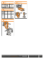 2
2
-
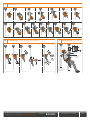 3
3
-
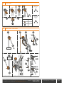 4
4
-
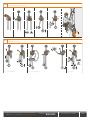 5
5
-
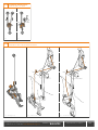 6
6
-
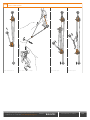 7
7
-
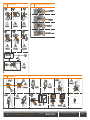 8
8
-
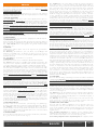 9
9
-
 10
10
-
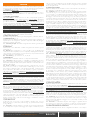 11
11
-
 12
12
-
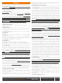 13
13
-
 14
14
-
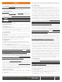 15
15
-
 16
16
-
 17
17
-
 18
18
-
 19
19
-
 20
20
-
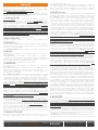 21
21
-
 22
22
-
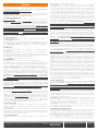 23
23
-
 24
24
-
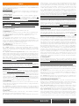 25
25
-
 26
26
-
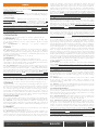 27
27
-
 28
28
-
 29
29
-
 30
30
-
 31
31
-
 32
32
-
 33
33
-
 34
34
-
 35
35
-
 36
36
-
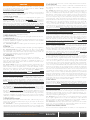 37
37
-
 38
38
-
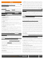 39
39
-
 40
40
-
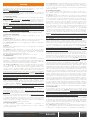 41
41
-
 42
42
-
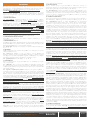 43
43
-
 44
44
-
 45
45
-
 46
46
-
 47
47
-
 48
48
-
 49
49
-
 50
50
-
 51
51
-
 52
52
-
 53
53
-
 54
54


Climbing Technology 2D67400WBSH Istruzioni per l'uso
- Tipo
- Istruzioni per l'uso
in altre lingue
Documenti correlati
-
Climbing Technology 2C39900ZPE Istruzioni per l'uso
-
-
-
-
-
Climbing Technology 2D793 Istruzioni per l'uso
-
-
-
-
Altri documenti
-
 Kong Secure Static Rope 10.5 Manuale utente
-
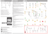 Kong Rolley Manuale utente
-
Nuki 010.318 Manuale utente
-
 Kong Trender Manuale utente
-
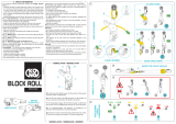 Kong Block Roll Manuale utente
-
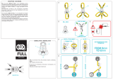 Kong Full Manuale utente
-
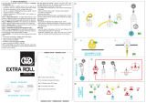 Kong Extra Roll Tactical Manuale utente
-
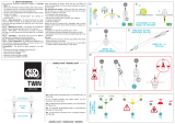 Kong Twin Tactical Manuale utente
-
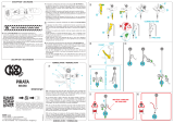 Kong Pirata Manuale utente
-
ISC RP074 Manuale utente


